

Page 1
OPERATOR’S MANUAL and DEALER SET-UP for SNAPPER
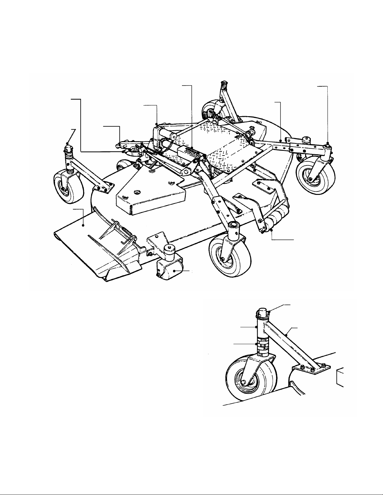
SPACERS
DECK LIFT
REAR
LINEAR
HEIGHT OF CUT
DECK FRAME
FRONT CASTER WHEELS
DISCHARGE
SIDE
CENTER DECK
LIFT ARM
73” MOWER for OUT FRONT Z-RIDER
INTRODUCTION: These instructions cover set-up of the Snapper 73” Mower for the Out Front Z-Rider.
The linkage on this mower has been designed to allow the use of the electric actuator on the deck to assist in
attaching the mower to the power unit. Follow and complete each step carefully.
WIRING
HARNESS
PLUG
CASTER
WHEELS
CHUTE
PIN
ACTUATOR
INDICATOR
(Shown Fully Extended)
ASSEMBLY
ROLLER
FIGURE 1 - NOMENCLATURE
STEP 1: Remove Mower Unit and Components from
the carton(s).
STEP 2: Adjust Rear Casters to lowest position by
removing Lynch Pins and placing Spacers on bottom
side of Tube. See Figure 2.
STEP 3: Remove the nuts and bolts from the Front
Caster Wheel Support Arms. See Figure 3.
STEP 4: Extend the Front Caster Wheels out until they
are aligned with the last set of holes. Reinstall nuts and
bolts. See Figure 3.
STEP 5: Check pin location at the lower end of the
Deck Stabilizer Channels. It should be in the middle
hole of the bracket. See Figure 4.
STEP 6: Remove contents of hardware bag which
includes (1) #9 Woodruff Key and (2) 3/8”-16 x 3/8” Set
Screws. Place Woodruff Key onto Gear Box Shaft on
mower deck. Slide Power Transfer Shaft over Gear Box
Shaft and make sure Woodruff Key remains in its
position. See Figure 5.
COPYRIGHT © 2001
SNAPPER INC.
ALL RIGHTS RESERVED
ROLLER
TUBE
(ON BOTTOM)
FIGURE 2
MANUAL NO. 7-3720 (Rev. 1, 7/25/01)
LYNCH PIN
REAR CASTER
Page 2

2
IMPORTANT SAFETY INSTRUCTIONS
WARNING: This powerful cutting machine is capable of amputating hands and feet and can throw objects that
can cause injury and damage! Failure to comply with the following SAFETY instructions could result in serious
injury or death to the operator or other persons. The owner of the machine must understand these instructions
and must allow only persons who understand these instructions to operate machine . Each person operating
the machine must be of sound mind and body and must not be under the influence of any substance, which
might impair vision, dexterity or judgment. If you have any questions pertaining to your machine which your
dealer cannot answer to your satisfaction, call or write the Customer Service Department at SNAPPER,
McDonough, Georgia 30253. Phone: (1-800-935-2967).
PROTECTION FOR CHILDREN
Tragic accidents can occur if the operator is not
alert to the presence of child ren. Children are often
attracted to the machine and the mowing activity.
Never assume that children will remain where you
last saw them.
1. KEEP children out of the mowing area and under
the watchful care of a responsible adult.
2. DO NOT allow children in yard when machine is
operated (even with the blades OFF).
3. DO NOT allow children or others to ride on
machine or on attachme nts (even with the blade
OFF). They may fall and be seriously injured.
4. DO NOT allow pre-teenage children to operate
machine. Local regulatio ns may restrict the age
of the operator.
5. ALLOW only adults or responsible teenagers
with mature judgment under close adult
supervision to operate machine.
6. DO NOT operate blades in reverse. STOP
BLADES. LOOK and SEE behind and down for
children, pets and hazards before and while
backing.
7. USE EXTRA CARE when approaching blind
corners, shrubs, trees, o r other objects that may
obscure vision.
PROTECTION AGAINST TIPOVERS
Slopes are a major factor related to loss-of-control
and tip-over accidents, which can result in severe
injury or death. All slopes require extra CAUTION. If
you cannot back up the slope or if you feel uneasy
on the slope, DO NOT mow it. Use extra care with
grass catchers or o ther attachments; thes e and turf
conditions affect the handling and the stability of the
machine.
1. DO NOT operate machine on slopes exceeding
15 degrees (27% grade).
2. Exercise EXTREME CAUTION on slopes above
10 degrees (18% grade). Turn blades OFF when
traveling uphill. Use a slow speed and avoid
sudden or sharp turns.
3. DO NOT operate machine back and f orth across
face of slopes. Operate up and down. Practice on
slopes with blades off.
4. AVOID uphill starts. If machine stops going
uphill or tires lose traction, turn blades OFF and
back slowly down the slope.
PROTECTION AGAINST TIPOVERS
(Continued Fr om Pr evi ous C olum n)
5. STAY ALERT for holes and other hidden hazards.
Tall grass can hide obstacles. Keep away from
ditches, washouts, culverts, fences and protruding
objects.
6. DO NOT operate machine near drop offs, ditches,
embankments, washouts, culverts, fences and
protruding objects. KEEP A SAFE DISTANCE (at
least 3 feet) away from edge of ditches and other
drop offs. The machin e could turn over if an edge
caves in.
7. Always begin forward motion slowly and with
caution.
8. Use weights or a weighted load carrier in
accordance with instructions supplied with a grass
catcher. DO NOT operate machine on slopes
exceeding 10 degrees (18% grade) when equipped
with grass catcher.
9. DO NOT put your foot on the ground to try to
stabilize the machine.
10. DO NOT operate machine on wet grass. Reduced
traction could cause sl iding.
11. DO NOT operate machine under any condition
where traction, s teering or sta bility is do ubtful.
12. Operator Protective Structures are available for this
machine through your local SNAPPER dealer.
PREPARATION
1. Read, understand and follow instructions and
warnings in this manual and on the machi ne, engine
and attachments. Know the controls, the safety
signs and the proper use of the machine before
starting . If the oper ators or me chanics ca nnot read
English, it is the owner’s responsibility to explain
this material to them.
2. Only mature, re sponsible persons shall operate or
service the machine and only after proper
instruction and training. The owner is responsible
for training the operators. Further, the
owner/operator can prevent and/or is responsible
for accidents or injuries occurring to themselves,
other people or proper ty.
3. Data indicates that operators age 60 and above, are
involved in a large percentage of mower-related
injuries. These operators should evaluate their
ability to operate the mower safely enough to
protect themselves and others from ser ious in jury.
Page 3

3
IMPORTANT SAFETY INSTRUCTIONS
PREPARATION
(Continued From Previous P age)
4. Handle fuel with extra car e. Fuels ar e flammabl e
and vapors are explosiv e. Use o nl y an app rov ed
fuel container. DO NOT remov e fuel cap or add
fuel with engine running. Add or drain fuel
outdoors only with engine stopped and cool.
Clean spilled fuel from machine. DO NOT
smoke.
5. Practice operation of machine with BLADES
OFF to learn controls and develop skills.
6. Check the area to be mowed and remove all
objects such as toys, wire, rocks, limbs and
other objects that could cause injury if thrown
by blades or interfere with mowing.
7. Evaluate the terrain to determine what
accessories and attachments are needed to
properly and safely perform the job. Only use
accessories and attachments approved by
SNAPPER.
8. Keep people and pets out of mowing area.
Immediately, STOP blades, STOP engine, and
STOP machine if anyone enters the area.
9. DO NOT operate machine unless all shields,
deflectors, switches, blade controls and other
safety devices are in place and functioning
properly.
10. Make sure all safety decals are clearly legible.
Replace if damaged.
11. Protect yourself when mowing and wear
appropriate clothing including safety glasses,
long pants, ear protection, hardhat and
substantial footwear with good traction. Long
hair, loose clothing or jewelry may get tangled
in moving parts.
12. Know how to STOP blades and engine quickly
in preparation for emergencies.
13. Use extra care when loading or unloading the
machine into a trailer or truck.
14. Check gras s catcher components frequently for
signs of wear or deterioration and replace as
needed to prevent injury from thrown objects
going through weak or worn spots.
OPERATION
1. Mount and dismount machine from left side.
2. Start engine from operator's seat. Make sure
blades are OFF and parking brake is set. Use
seat belts if provided.
3. DO NOT leave machine with engine running.
Stop engine. Stop blades. Set brake. Remove
key.
4. DO NOT operate machine unless properly
seated with feet on foot rests or pedal(s).
5. DO NOT operate machine while under the
influence of alcohol or drugs.
OPERATION
(Continued From Previous Column)
6. STOP MACHINE on level ground, lower deck,
engage parking brake and make sure engine
and blades have stopped before removing
grass catcher or unclogging mower to prevent
injury to hands or feet.
7. Blades must be OFF exce pt w hen cut ting grass.
Set blades in highest position when mowing
over rough ground.
8. Keep hand s and feet awa y from rotating blad es
underneath deck. DO NOT place foot on ground
while BLADES are ON or machine is in motion.
9. DO NOT operate machine without entire grass
catcher or guards in place. DO NOT point
discharge at people, passing cars, windows or
doors.
10. Slow down before turning.
11. Watch out for traffic when near or crossing
roadways.
12. STOP engine immediately after striking an
object or if an abnormal vibration occurs.
Remove key. Remove and disconnect the
sparkplug wire. M ake necessary repairs before
resuming operation.
13. Mow only in daylight or with good artificial light.
14. Move motion control levers SLOWLY to
maintain control during speed and directional
changes.
15. Exerci se CAUTION w hen pulling load s. DO NOT
pull loads greater than 300 pounds. Avoid jack
knifing. DO NOT turn sharply.
16. DO NOT operate engine in enclosed areas.
Engine exhaust gases contain carbon
monoxide, an odorless and deadly poison.
MAINTENA NCE
1. DO NOT store machine or fuel container inside
where fume s may reach an open flame, sp ark or
pilot light such as in a water heater, furnace,
clothes dr y er or othe r ga s a p pl iance. Al l o w e n gi ne
to cool before storing machine in an enclosure.
Store fuel container out of the reach of children in
a well ventilated, unoccupied building. Shut off
fuel (when equipped with valve) while storing or
transporting machine.
2. Clean grass and debris from engine, mufflers,
drives and cutting units to help prevent
overheating and fires. Clean up fuel, oil and
excess grease.
3. When draining fuel tank, drain fuel into an
approved container outdoors and away from open
flame.
4. Check brakes frequently; adjust, repair or replace
as needed.
5. Keep all bolts, nuts and screws properly tight.
Check that all cotter pins are in pr oper posi tion.
6. Always provide adequate ventilation when
running engine. Engine exhaust gases contain
carbon mono xi de, a n odor less an d dead ly po iso n.
Page 4

4
IMPORTANT SAFETY INSTRUCTIONS
MAINTENANCE
(Continued From Previous Page)
7. Disconnect battery before performing
maintenance or service. Cranking engine could
cause injury. Disconnect negative (black) cable
from battery first and positive (red) cable last.
Reconnect positive first and negative last.
Charge battery in an open, well ventilated area
away from spark and flames. Unplug charger
before connecting or disconnecting from battery.
Wear protective clothing and insulated gloves.
8. Park machine on level ground. DO NOT work
under machine without safety blocks.
9. Service engine and clean, adjust or repair only
when engine and blades are stopped. Remove
spark plug wire(s) fro m spark plu g(s) and se cure
wire(s) away from spark plug(s).
10. DO NOT change engine governor speed settings
or overspeed engine. DO NOT make adjust ments
with the engine running.
11. Lubricate machine at intervals specified in
manual to prevent controls from binding.
12. Mower blades are sharp and can cut. Wrap the
blades or wear heavy leather gloves and use
CAUTION when handling them. Never straighten
or weld blades, only replace them.
13. DO NOT test for spark by grounding spark plug
next to spark plug hole; spark plug could ignite
gas exiting engine.
14. Carefully release pressure from components
with stored energy.
15. Have machine serviced by an authorized
SNAPPER dealer at least once a year and have
the dealer install any n ew safety devices. Never
allow untrained personnel to service machine.
16. Use only genuine SNAPPER replacement parts
to assure that original standards are maintained.
Page 5

5
1) REMOVE HARDWARE.
2) EXTEND CASTER OUT TO LAST SET OF
FRO
NT CASTER
DECK STABILIZER
CHANNELS
PIN SHOULD BE IN MIDDLE
NOTE: DECK BRACKET HAS
#9 WOODRUFF KEY
GEARBOX
3/8 - 16 X 3/8”
TELESCOPING
HITCH
PULL OUT, ROTATE
UNLATCHED
HITCH
TIMING
TIMING
ROD
JAM NUT SHOWN
HOLES.
3) REINSTALL HARDWARE.
HARDWARE
DECK FRAME
HOLE
DECK SIZE IDENTIFICATION
NUMBERS STAMPED INTO ITS
SIDE. PIN LOCATION IN
CORRECT HOLE SHOULD
CORRESPOND WITH DECK SIZE.
SUPPORT ARM
FIGURE 3
FIGURE 4
FWD
ASSEMBLY
STEP 7: Secure Transfer Shaft to Gear Box Shaft
using two screws. See Figure 5. Tighten securely.
STEP 8: Place a 2x4 under each rear caster. Block the
front caster wheels so that they will not roll.
STEP 9: Locate jam nuts on the right timing rod and
the right rear deck hanger rod. See Figures 6 and 12.
Note position of nuts. You must return both nuts to this
position after attaching the deck.
TIGHTENED
AGAINST SWIVEL
ROD
TIMING ROD
FIGURE 6
STEP 10: Run each (2) jam nut up against the swivels
on the timing rod and the hanger rod. The deck linkage
will not float when the nuts are in this position. This will
allow the use of the electric actuator on the deck to lift
and attach the deck frame to the power unit.
STEP 11: Located on the hitch plates at the front of the
Power Unit, rotate the Spring-Loaded Hitch Latch Pins to
the unlatched position. See Figure 7.
STEP 12: Engage Parking Brake. Start Power Unit.
LATCH
PIN
UP TO UNLATCH
POSITION
(1/4 X 7/8)
SET SCREWS
FIGURE 5
SHAFT
POSITION
PLATE
FIGURE 7
Page 6

6
WARNING
HITCH LATCH PINS
-
LIFT
HITCH
PULL LOCK
POWER
SLIDE
NOTE: DECK IS NOT SHOWN FOR CLARITY. DECK SHOULD
A small movement of the joystick can cause the
power unit to move instantly. Move joystick very
carefully and slowly.
STEP 13: Disengage Parking Brake. Carefully move
Power Unit close to Mower Deck to connect Power Unit
and Deck Wiring Harness. Turn engine “OFF”. Plug in
Deck Lift Wiring Harness from Power Unit into Deck Lift
Wiring Harness. Turn Switch key to “ON” position (Do
Not start engine!). Hold Deck Lift Switch in the “DOWN”
position until the lift arm pins are in line with the hitch
plates. See Figures 7 & 8.
STEP 14: Engage Parking Brake. Start engine and
drive Power Unit forward until Lift Arm Pins are
completely inserted into Hitch Plates. Once Lift Arm is in
position with Hitch Plates, move Deck Lift Switch to the
“UP” position and Lift Arm Pins will move lower into Hitch
Plates. Stop engine. Rotate both Hitch Latch Pins
around until they lock Lift Arm into Hitch Plates. See
Figure 8.
ANTI-PINCH PINS
ROTATE DOWN TO
LATCH POSITION
PLATE
ARM
PIN
FIGURE 8
STEP 15: Return jam nuts on the timing rod and hanger
rod back to original position. Refer to STEP 9.
STEP 16: Insert Power Transfer Shaft onto Power
Take-Off (PTO) Shaft. When sliding Transfer Shaft onto
PTO, the Lock Collar must be pulled back until Collar
encounters the groove around the shaft. Release Collar
so it locks/clicks into place in the groove. See Figure 9.
IMPORTANT: Make sure Drive Shaft is properly locked
into groove and cannot be moved from that position. If
Transfer Shaft is not properly installed, damage to Drive
Shaft or PTO could result.
COLLAR BACK
TRANSFER
SHAFT
OVER
SHAFT
BE IN POSITION AT THIS POINT IN THE SET-UP.
FIGURE 9
Page 7

7
MAKING INITIAL DECK ADJUSTMEN
TS
ADJUST NUT “IN” OR
TIMING
TIMING ROD
TIMING
REAR DECK HANGER
FRONT DECK
OUTER/DISCHARGE
LEVEL AREA
STEP 17: Start engine and move unit to a level surface
for deck adjustments.
STEP 18: Using the right, Discharge, blade as a
reference, adjust both Timing Rods equal turns until front
tip of blade is 1/4” lower than the rear tip. See Figures 10 &
11.
“OUT” TO TILT DECK
FRONT-TO-REAR
ROD
STEP 19: Level deck from side-to-side by adjusting the
Deck Hanger Rods up or down as required. See Figure
12.
ROD
HANGER ROD
FIGURE 12
NOTE: Both Hanger Rods should be adjusted at the
same increments to keep deck level. For “Fine Tuning”,
either Hanger Rod can be adjusted individually.
STEP 20: Remove Lynch Pins and reposition spacers
evenly above and below the tube on rear casters.
ROD
FIGURE 10
BLADE
IMPORTANT: The rear casters are adjustable. To
lessen the amount of mower scalping, adjust rear
casters by repositioning spacers to match the type of
terrain being mowed.
STEP 21: Check installation thoroughly. Start engine
DECK
FWD
and move machine outside.
CHECK GEAR BOX
Periodically check gear box lubrication.
1. Remove cap bolt located on the top of gear box.
There should be visible oil inside gear box.
2. If gear box oil is low or is not visible, add a small
quantity of 80W90 gear oil.
X
X(-1/4)
3. Replace cap bolt and tighten securely.
CUTAWAY VIEW - OUTER/DISCHARGE BLADE
FIGURE 11
Page 8

8
SERVICE & LUBRICATION
HOURS PROCEDURE COMMENTS
BREAK-IN.......................................Check all Grease Points and add if necessary
........................................................Check all Fasteners for proper tightness.
DAILY..............................................Remove Debris from under Belt Cover.........................More often if needed.
........................................................Sharpen Cutter Blades.................................................Tighten to 60-75 Ft.-Lbs.
........................................................Grease Cutter Spindle Bearings...................................Use Chevron SRI Grease or equal.
........................................................Inspect Interlock Switches for Damage........................Replace if Needed.
........................................................Inspect Belts for Wear or Damage...............................Replace if Needed.
WEEKLY.........................................Check Tire Pressure.....................................................Add or Adjust as required.
........................................................Check Safety Interlock System.....................................Inspect OPC Switch for proper Operation.
........................................................Grease Caster Wheel Bearings....................................General Purpose Grease.
........................................................Grease Caster Support Arms.......................................General Purpose Grease.
........................................................Grease Idler Arm Pivots on Cutter Deck......................General Purpose Grease.
MONTHLY.......................................Lube Controls and Linkages.........................................Use Medium Duty Oil.
........................................................Gear Box Lubrication....................................................Use 80W90 Gear Oil
........................................................ .....................................................................................(Total Capacity is 16 Ounces)
DECALS
DECAL P.N. 4-6371
DECAL P.N. 7-3647
DECAL P.N. 1-3010
Page 9

9
2 YEAR LIMITED WARRANTY
For two (2) years from purchase date for the original purchaser's use, SNAPPER, through any authorized
SNAPPER dealer will replac e, free of charge (ex cept for taxes where applicab le), any part or par ts found upon
examination by the factory at McDonough, Georgia, to be defective in material or workmanship or both.
SNAPPER FIELD SERVICEABLE SPI NDL ES an d their components us e d o n SNAPPER PRO® Mid Size walks
and SNAPPERZRIDER® ride on commercial equipm ent have a three (3) year lim ited warranty against def ects
in material or workmanship or both.
All transportation cos ts incurred by the purchaser in submitting material to a n authorized SNAPPER de aler for
replacement under this warranty must be paid by the purchaser.
This warranty does not apply to engines and their com ponents, and batteries, as these item s are warranted
separately. This warranty does not apply to parts that have been damaged by accident, alteration, abuse,
improper lubrication, normal wear, or other cause beyond the control of SNAPPER. This warranty does not
cover any machine or component that has been altered or modified, changing safety, performance, or durability.
Batteries have a one (1) year prorated warranty period with free r eplacement if required durin g the first ninety
(90) days from the or iginal purchase date. SNAPPER will not be responsible for any installation cos t incurred.
The battery warranty only covers original equipment batteries and does not cover damage to the battery or
machine caused by neglect or abuse, destruction by fire, explosion, freezing, overcharging, improper
maintenance, or use of improper electrolyte.
There is no other express warranty.
DISCLAIMER OF WARRANTY
Implied warranties, including those of merchantability and fitness for a particular purpose, are limited to
two (2) years from pu rchase dat e fo r the orig inal purchas er's u se, and up to the exten t perm itted by law
and all implied warranties are excluded. This is the exclusive remedy. Liabilities for consequential
damages, under any and all warranties are excluded.
Some states do not allow limitations on how long an implied warranty lasts, or do not allow the
exclusion or limitation of incidental or consequential damages, so the above limitation or exclusion
may not apply to you.
This warranty gives you specific legal rights, and you may also have other rights which vary from state to state.
WARNING: THE USE OF REPLACEMENT PARTS OTHER THAN GENUINE SNAPPER PARTS MAY
IMPAIR THE SAFETY OF SNAPPER PRODUCTS AND WILL VOID ANY LIABILITY AND WARRANTY BY
SNAPPER ASSOCIATED WITH THE USE OF SUCH PARTS.
IMPORTANT: Please fill out the attached SNAPPER Product Registration Card immediately and mail to:
Snapper ’s P r od uct Regis tration Ce nt e r, P.O. Box 1379, McDonough, Georgia. 30253
COPYRIGHT © 2001
SNAPPER INC.
ALL RIGHTS RESERVED
MANUAL NO. 7-3720 (Rev. 1, 7/25/01)
 Loading...