

Page 1

Safety Instructions & Operator's Manual for
MID MOUNT Z-RIDER
ZERO TURNING
HYDRO DRIVE
SERIES 2
MODELS
NZMJ23522KH
NZMJ25612KH
MODEL NUMBER EXPLANATION
INI ;
MODEL DESIGNATION ._
DRIVE SYSTEM TYPE
MOWER ORIENTATION
ENGINE HP *
N - Model Designation 23 - Engine Horse Power 2 - Series Designation KH - Kohler Engine
Z -Zero Turning - Hydro Drive 25- Engine Horse Power
M - Mid Mount Mower 52 - 52" Mower Width
J - Joystick Control 61 - 61" Mower Width
Thank you for buying a SNAPPER Product! Before operating your machine, read this manual carefully and pay
particular attention to the "IMPORTANT SAFETY INSTRUCTIONS" on Pages 2 - 4. Remember that all power
equipment can be dangerous if used improperly. Also keep in mind that SAFETY requires careful use in
accordance with the operating instructions and common sense!
NOTE: Specifications are correct at time of printing and are subject to change without notice.
* Actual sustained equipment horsepower will likely be lower due to operating limitations and environmental factors.
,dnm_ in IIIIll=lllnh
SNAPPER A DIVISION OF SIMPLIC]TY _']FG INC
ALL RIGHTS RESERVED
: I_JI _31_zl :! I KHI
I
POWER UNIT
MANUAL No. 7-4417 (Rev. I - 9/3/04)
ENGINE TYPE
SERIES DESIGNATION
MOWER DECK SIZE
Page 2

TABLE OF CONTENTS
IMPORTANT SAFETY INSTRUCTIONS ........................................................................ 2-4
TABLE OF CONTENTS ..................................................................................................... 5
SECTION 1 - FAMILIARIZATION ...................................................................................... 6
SECTION 2 -SAFETY MESSAGES AND SYMBOLS .................................................... 7-8
SECTION 3 - OPERATING INSTRUCTIONS ............................................................... 9-13
Pre-start Checklist ................................................................................................. 9-10
Starting & Stopping Engine, Blades & Parking Brake ..................................... 10-11
Starting & Stopping Mower Blades ........................................................................ 11
Parking Brake ........................................................................................................... 11
Cutting Height Adjustment ...................................................................................... 12
Driving & Stopping Machine ............................................................................... 12-13
Safety Interlock System Check ............................................................................... 13
SECTION 4 - MAINTENANCE INSTRUCTIONS ....................................................... 14-18
Change Engine Oil .................................................................................................... 14
Check Mower Blade ................................................................................................. 14
Check Mower Drive Belt .......................................................................................... 16
Check Belt Tension .................................................................................................. 16
Service - After every 25 Hours (Engine Components) ......................................... 16
Service - After every 25 Hours (Mower Components) ......................................... 16
Lubrication ................................................................................................................ 16
Mower Blade Spindle Lubrication ...................................................................... 16
Mower Deck Linkage Lubrication ...................................................................... 16
Front Wheel Bearings Lubrication ..................................................................... 16
Hydro Pump Lubrication ..................................................................................... 16
Other Lubrication ................................................................................................. 16
Before Operating Machine ....................................................................................... 16
Annually - End of Season ................................................................................... 16-17
Engine Service .......................................................................................................... 16
Fuel Filter Replacement ........................................................................................... 17
Deck Removal ...................................................................................................... 17-18
Hydraulic Fluid Filters .............................................................................................. 18
SECTION 5 - ADJUSTMENTS AN D REPAIR ............................................................ 19-27
Neutral Position Adjustments ............................................................................ 19-20
Mower Deck Adjustment (Levelness) ................................................................ 20-21
Parking Brake Adjustment ...................................................................................... 21
Traction Belt Tension & Replacement .................................................................... 22
Blade Brake/Electric Clutch Adjustment ............................................................... 22
Tracking Adjustment ................................................................................................ 23
Mower Drive Belt Removal & Replacement ........................................................... 23
Engine Adjustments & Repair ................................................................................. 24
Mower Blade Replacement ...................................................................................... 24
Mower Blade Sharpening ........................................................................................ 24
Battery Removal ....................................................................................................... 25
Battery Installation ................................................................................................... 25
Battery Charging ...................................................................................................... 25
Battery Testing ......................................................................................................... 26
New Battery Preparation .......................................................................................... 26
Mower Spindle Bearing Replacement .................................................................... 27
Hydraulic System, Purging ...................................................................................... 28
TROUBLESHOOTING ................................................................................................ 29-30
SERVICE SCHEDULE ..................................................................................................... 31
WARRANTY ..................................................................................................................... 32
PRIMARY MAINTENANCE ......................................................................................... 33-36
PRODUCT REGISTRATION FORM ................................................................................ 37
MaintenancelReplacement Parts ....................................................................... 31
IMPORTANT
NOTICE: Operator Protective Structures are available as optional kits for the Mid-Mount and Out-Front Z-Rider
machines. These structures, when installed and used properly can offer additional security to the operator
against serious injury in the event of a tip over accident. Operator Protective Structures may be required by local
ordinances. Discuss your mowing application and ordinances with your local Snapper Dealer.
5
Page 3
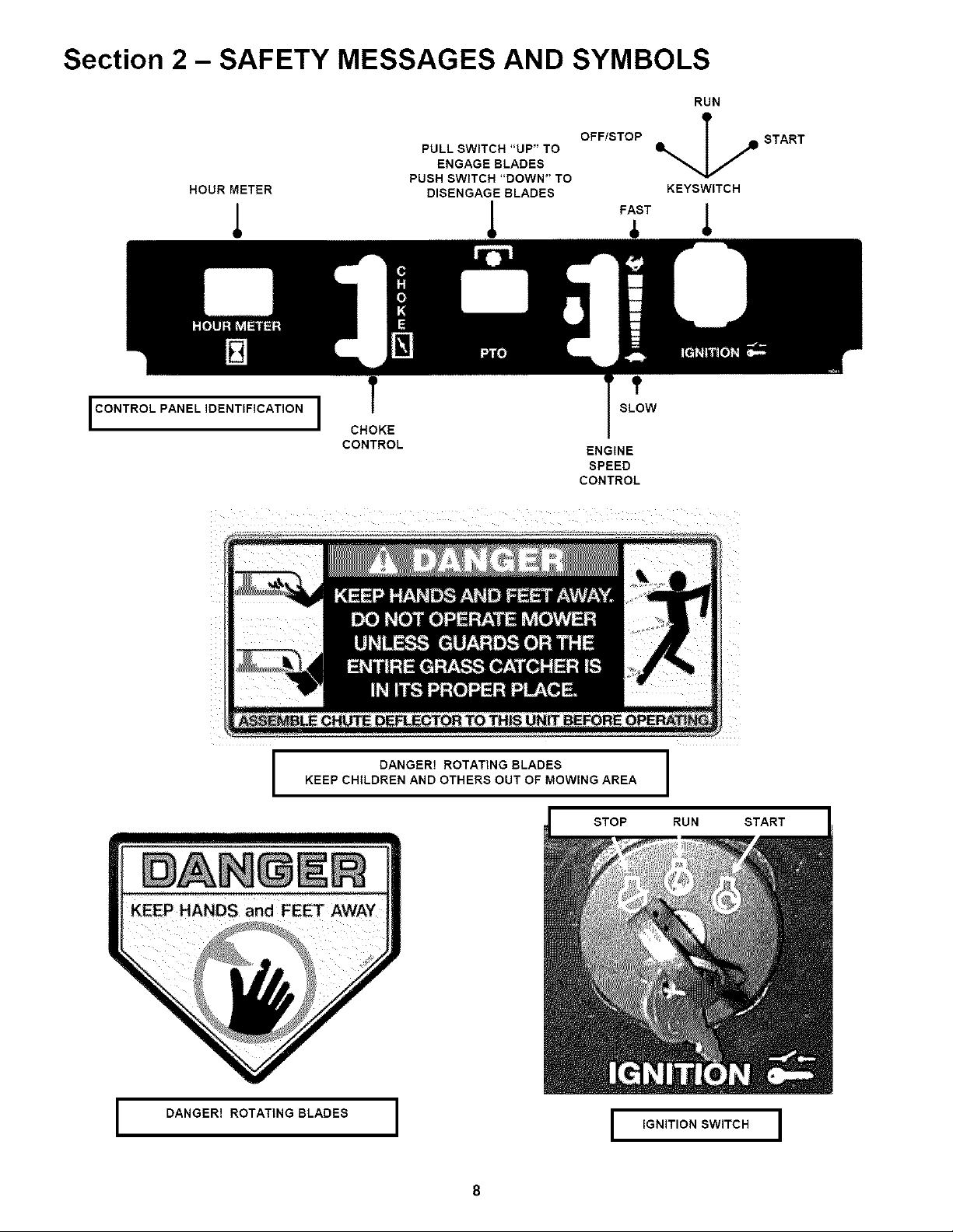
Section 2 - SAFETY MESSAGES AND SYMBOLS
RUN
HOUR METER DISENGAGE BLADES KEYSWITCH
1 I T I
I CONTROL PANEL IDENTIFICATION I
CHOKE
CONTROL
OFF/STOP
PULL SWITCH "UP" TO I1% l _
ENGAGE BLADES
PUSH SWITCH "DOWN" TO
ENGINE
SPEED
CONTROL
_ T _
SLOW
START
KEEP CHILDREN AND OTHERS OUT OF MOWING AREA
I DANGER! ROTATING BLADES I
I DANGER! ROTATING BLADES I
STOP RUN START
I IGNITION SWITCH I
Page 4

Section 3 - OPERATING INSTRUCTIONS
3.2.1. STARTING ENGINE
NOTE: If after 5 seconds of cranking the engine
does not start, release the key. Attempt starting
again after waiting for approximately 20 seconds.
7, After engine starts, move the choke control to
the "OFF" or no choke position. Allow a brief
warm-up until engine runs smooth.
3.2.2. STOPPING ENGINE
1, Stop engine by turning key to "STOP" position.
Move engine speed to the Turtle "SLOW" position
and turn key to "STOP". See Figure 3.6.
SHOWN FROM OPERATOR'S VIEW POINT
FIGURE 3.6
3.2.5. PARKING BRAKE
1, Engage parking brake by pulling the parking brake
lever back to the engaged position.See Figure 3.7.
NOTE: To engage the parking brake, the joystick
control must first be placed in the center neutral
position.
2 Release parking brake by pushing parking brake
leverforward to the released position.See Figure3.8.
WARNING
DO NOT operate blades in reverse. STOP blades. I
LOOK and SEE behind and down for children, pets,
and hazards before and while backing. I
3.2.3. STARTING MOWER BLADES
1. Start engine and set engine speed control to
the Rabbit "FAST" position. See Figure 3.5.
2, Pull the Blade Switch up to the "ON" position to
engage or turn "ON" the mower blades.
See Figure 3.2.
3.2.4. STOPPING MOWER BLADES
1. Push Blade Switch down to "OFF" position to
disengage or turn "OFF" the blades.
2, Move engine speed control to the Turtle
"SLOW" position. Turn key to "STOP" position.
blades are disengaged, they should come to a
complete stop in 7 seconds. If the blades continue
to rotate after 7 seconds, the electric clutch should
be checked. Adjustment or replacement of electric
clutch may be necessary. Return the machine to an
authorized Snapper dealer for replacement. DO
NOT CONTINUE to operate mower if blades fail to
stop in 7 seconds.
WARNING
FIGURE 3.7
PARKING BRAKE
LEVERIN RELEASED
"OFF'POSITION
FIGURE 3.8
DO NOT park the machine on slopes. DO NOT I
machine with engine running. Stop engine.
blades. Engage parking brake. Remove key.
11
Page 5

Section 5 - ADJUSTMENTS & REPAIR
5.1 NEUTRAL POSITION ADJUSTMENTS 5.2
(Continued From Previous Page)
12, Move motion control lever to the neutral position
and engage the parking brake, See Figure 3.7, hold
connecting rod up to the activation assembly and
check length of rod. Tie rod end bolt must align with
the activation assembly. If bolt is not aligned with the
activation assembly, adjust tie rod. Loosen jam nut
that secures tie rod. Rotate tie rod in or out to align
with hole in activation assembly. Repeat step for
other hydro pump. See Figure 5.4.
HYDRO PUMP _,
ACTIVATION PUMP
ASSEMBLY .....
in HYDRO
LOOSEN NUT AND
ROTATE TIE ROD END
TIE ROD END
IN OR OUT TO ALIGN
WITH ACTIVATION
MOWER DECK & COMPONENT ADJUSTMENTS
The leveling procedures for the 61 deck differ from
the 48 and 52 decks. The 61 deck replaces the two
rear eyebolts with slotted brackets_ and uses 1 1/4"
leveling blocks in place of the 1" blocks. Follow and
complete each step carefully.
5,2.1, MOWER DECK ADJUSTMENT (LEVELNESS)
SIDE to SIDE and FRONT to REAR
Before making deck leveling adjustments, inflate rear
tires to 12 PSI and front tires to 25 PSI. When
adjusted correctly, the deck will be level side to side
within 1/8", have a low cut setting of approximately 1"
(1 1/4" for 61 deck) and the blades pitched
approximately 3/16" higher at the rear.
1. Place machine on a smooth level surface.
2. Check side to side level by rotating blades until
tips are pointing to the sides of the deck. Check the
measurement of outside blade tips to the ground on
both blades. The measurement of each of the outside
blade tips should be within 1/8" of each other. If
measurement of the blade tips is not within 1/8",
adjustment should be made.
3. Move deck lift lever and set the mower deck to the
highest cutting position.
4. Relive tension on deck lift assist spring by
loosening nut on eyebolt. Refer to Section
"Removing Deck".
5. Place 1" blocks (1 1/4" for 61 deck) under the front
and rear edge of the mower deck.
6. Move deck lift lever and set the mower deck to the
lowest cutting position.
6. Loosen the nuts and bolts that secure both front
deck support chains. Adjust chains until tight and
retighten bolts and nuts. Torque to 70 ft. Ibs. See
Figure 5.5.
BOLT IS SHOWN
ALIGNED WITH
HOLE
FIGURE 5,4
13. Once tie rod end bolt is aligned with activation
assembly insert into hole and reinstatI washers and
nut that secure bolt to assembly. Tighten securely.
Tighten tie rod jam nut securely.
14. Start engine, disengage parking brake, and
check rotation of the rear wheels.
15. Reinstall both hydro pump fans. Reinstall
washer and bolt. Tighten bolt securely.
16. Reinstall screen and tighten retaining hardware
securely.
FRONT
LIFT ARM
DECK HANGER
BRACKET
LOOSEN BOLT AND NUT,
TIGHTEN CHAIN. SECURE
BOLTS AND NUTS
FIGURE 5.5
20
Page 6

Section 5 - ADJUSTMENTS & REPAIR
WARNING
DO NOT attempt any maintenance, adjustments or
service with engine running. STOP engine. STOP
blades. Set brake. Remove key. Remove spark plug
wires and secure away from spark plugs. Engine
and components are HOT. Avoid serious burns,
allow sufficient time for all parts to cool.
5.3 TRACTION BELT TENSION
The traction drive belt tension does not require
adjustment. If the belts are slipping, they will have to be
replaced.
J-BOLT
FIGURE 5.9
5.4 TRACTION BELT REPLACEMENT
1. Remove clutch to deck belt. See Figure 5.10
2. Turn lock nut out to the end of J-Bolt, reducing
spring tension. Unhook traction idler spring from bolt
in frame. See Figure 5.9
3. Remove anti-rotation bracket. See Figure 5.10
4. Disconnect the electric clutch from main wire
harness.
5, Remove traction belts from around engine pulley
and hydro pumps.
6, Install new belts and route around engine pulley
and hydro pump pulleys.
7, Reconnect electric clutch to main wire harness.
8, Reinstall anti-rotation bracket and tighten nuts
securely.
9, Reattach traction idler spring. Run lock nut all
the way to the end of the threads on the J-Bolt.
Tighten jam nut securely. See Figure 5.10.
10. Reinstall electric clutch to deck belt.
UNHOOK TRACTION
DRIVE IDLER SPRING
!IREMOVECLUTCH
REMOVEANTI-
ROTATION BRACKET
FIGURE 5.10
5.5 BLADE BRAKE/ELECTRIC CLUTCH ADJUSTMENT
The blade switch engages the electric clutch when
pulled out to the "ON" position. When the blade
switch is in the "ON_' position the cutting blade(s)
are engaged. The blade switch disengages the
electric clutch when the blade switch is pushed in
to the "OFF" position. When the blade switch is in
the "OFF" position the cutting blade(s) are
disengaged. The electric clutch is adjustable. The
blades should stop rotation in 7 seconds or less. If
the electric clutch fails to stop the blades rotation in
7 seconds, adjustment is necessary.
1. Insert a feeler gauge into the three slots on the
electric clutch.
2. Check gap through all three slots in the side of
the clutch. The gap should be set at .015.
3. If gap is incorrect rotate nuts in or out to achieve
the correct gap. See Figure 5.11.
NOTE: Electric Clutch is shown removed from the
machine. Removal is not necessary for adjustment.
INSERT FEELER GAUGE.
GAP SHOULD BE .015
S'
j_
ROTATE NUTS
IN OR OUT
TO ACHIEVE
CORRECTGAP
22
FIGURE 5.11
Page 7
Section 5 - ADJUSTMENTS & REPAIR
WARNING
Shield the positive terminal with terminal cover
located on battery harness. This prevents metal from
touching the positive terminal, which could cause
sparks. Cables must be connected to battery
terminals in the proper position. RED (Positive)
cable must go to the ( + ) terminal. BLACK (Negative)
cable must go to the ( - ) terminal. If battery is
removed, DO NOT operate engine without insulating
Positive + battery cable terminal with electrical tape,
or sparking from the battery cables can result.
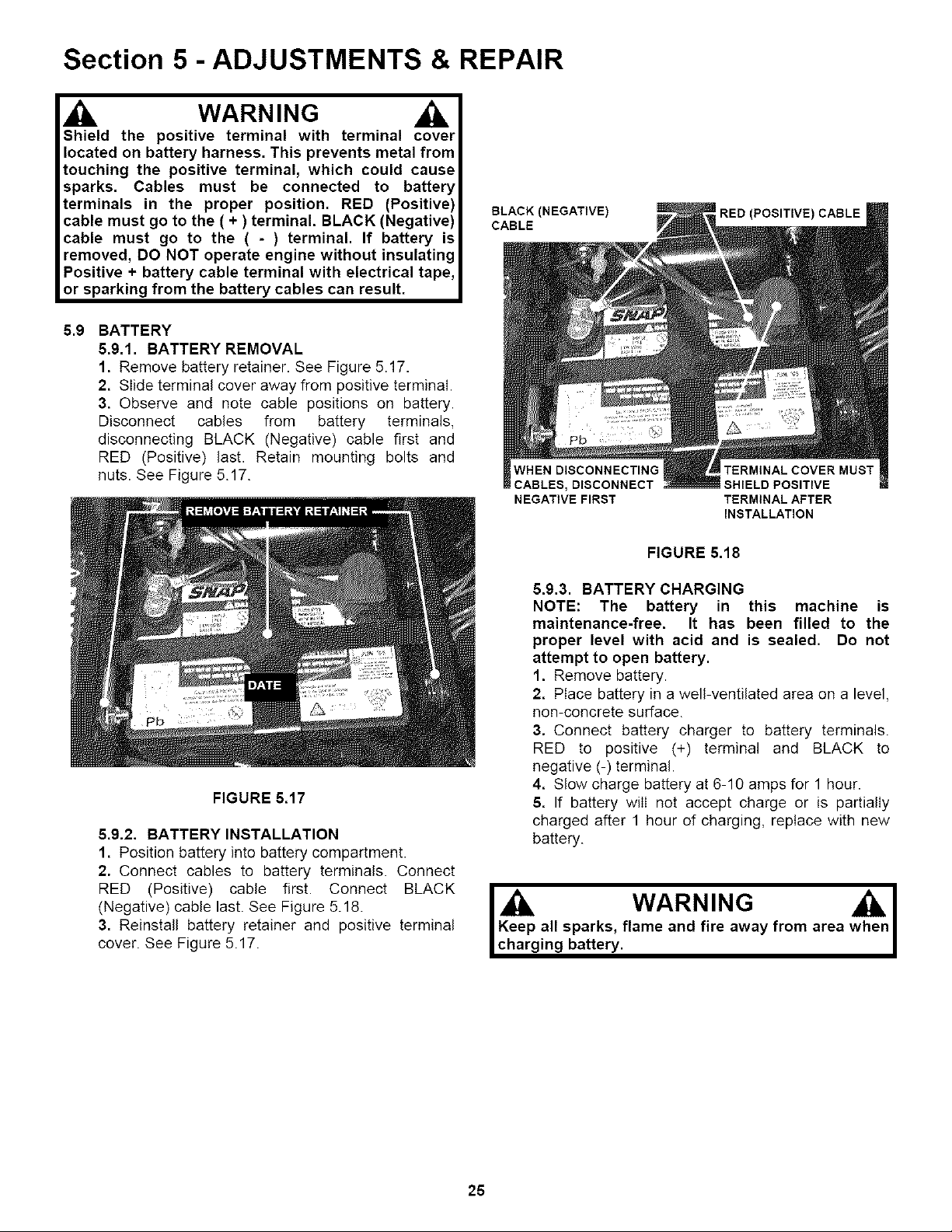
5.9 BATTERY
5.9.1. BATTERY REMOVAL
1, Remove battery retainer. See Figure 5.17.
2. Slide terminal cover away from positive terminal.
3. Observe and note cable positions on battery.
Disconnect cables from battery terminals,
disconnecting BLACK (Negative) cable first and
RED (Positive) last. Retain mounting bolts and
nuts. See Figure 5.17.
BLACK (NEGATIVE)
CABLE
WHEN DISCONNECTING
CABLES, DISCONNECT
NEGATIVE FIRST
RED (POSITIVE) CABLE
SHIELD POSITIVE
TERMINAL AFTER
INSTALLATION
FIGURE 5.17
5.9.2. BATTERY INSTALLATION
1. Position battery into battery compartment.
2. Connect cables to battery terminals. Connect
RED (Positive) cable first. Connect BLACK
(Negative) cable last. See Figure 5.18.
3. Reinstall battery retainer and positive terminal
cover. See Figure 5.17.
FIGURE 5.18
5.9.3. BATTERY CHARGING
NOTE: The battery in this machine is
maintenance-free. It has been filled to the
proper level with acid and is sealed. Do not
attempt to open battery.
1. Remove battery.
2. Place battery in a well-ventilated area on a level,
non-concrete surface.
3. Connect battery charger to battery terminals.
RED to positive (+) terminal and BLACK to
negative (-) terminal.
4. Slow charge battery at 6-10 amps for 1 hour.
5. If battery wilI not accept charge or is partially
charged after 1 hour of charging, replace with new
battery.
Keep all sparks, flame and fire away from area
charging battery.
WARNING w I
25
 Loading...