

Snapper NZMJ25611KH, NZMJ23521KH Owner’s Manual

Safety Instructions & Operator's Manual for
MID MOUNT Z-RIDER
ZERO TURNING
HYDRO DRIVE
SERIES 1
MODELS
NZMJ23521KH
NZMJ25611KH
MODEL NUMBER EXPLANATION
INI;
MODEL DESIGNATION ._1
DRIVE SYSTEM TYPE
MOWER ORIENTATION
ENGINE HP
N - Model Designation 23 - Engine Horse Power 1- Series Designation KH - Kohler Engine
Z -Zero Turning - Hydro Drive 25- Engine Horse Power
M - Mid Mount Mower 52 - 52" Mower Width
J - Joystick Control 61 - 61" Mower Width
Thank you for buying a SNAPPER Product! Before operating your machine, read this manual carefully and pay
particular attention to the "IMPORTANT SAFETY INSTRUCTIONS" on Pages 2 - 4. Remember that all power
equipment can be dangerous if used improperly. Also keep in mind that SAFETY requires careful use in
accordance with the operating instructions and common sense!
SNAPPER McOooouoh
COPYRIGHT © 2003
SNAPPER PRODUCTS INC
ALL RIGHTS RESERVED
: I_JI _31_zl , I KHI
I
POWER UNIT
GA., 30253 U.S.A.
MANUAL No. 7-5593 (Rev I, 8/5/03)
ENGINE TYPE
SERIES DESIGNATION
MOWER DECK SIZE
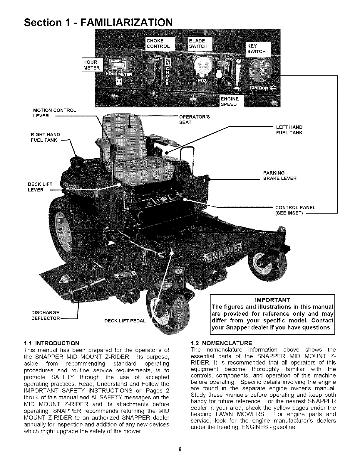
Section 1 - FAMILIARIZATION
MOTION CONTROL
LEVER
\
RIGHT HAND
FUEL TANK
DECK LIFT
LEVER
ENGINE
SPEED
OPERATOR'S
SEAT
LEFT HAND
FUEL TANK
PARKING
BRAKE LEVER
DISCHARGE
DEFLECTOR,
DECK LIFT PEDAL
1.1 INTRODUCTION
This manual has been prepared for the operator's of
the SNAPPER MID MOUNT Z-RIDER Its purpose,
aside from recommending standard operating
procedures and routine service requirements, is to
promote SAFETY through the use of accepted
operating practices. Read, Understand and Follow the
IMPORTANT SAFETY INSTRUCTIONS on Pages 2
thru 4 of this manual and All SAFETY messages on the
MID MOUNT Z-RIDER and its attachments before
operating. SNAPPER recommends returning the MiD
MOUNT Z-RIDER to an authorized SNAPPER dealer
annually for inspection and addition of any new devices
which might upgrade the safety of the mower.
CONTROL PANEL
(SEE INSET)
IMPORTANT
The figures and illustrations in this manual
are provided for reference only and may
differ from your specific model. Contact
your Snapper dealer if you have questions
1.2 NOMENCLATURE
The nomenclature information above shows the
essential parts of the SNAPPER MID MOUNT Z-
RIDER. It is recommended that all operators of this
equipment become thoroughly familiar with the
controls, components, and operation of this machine
before operating. Specific details involving the engine
are found in the separate engine owner's manual.
Study these manuals before operating and keep both
handy for future reference. For the nearest SNAPPER
dealer in your area, check the yellow pages under the
heading LAWN MOWERS. For engine parts and
service, look for the engine manufacturer's dealers
under the heading, ENGINES - gasoline.
6

Section 2 - SAFETY MESSAGES AND SYMBOLS
DANGER ! ROTATING PARTS
KEEP AWAY FROM MOVING PARTS
MOTION CONTROLLEVER(JOYSTICK)
MULT-D RECT ONAL
REVERSE
I
I PARKING BRAKE LEVER OPERATION I
TO O_F._AT :
TO gT_z
I WARNING ! AVOID SERIOUS INJURY OR DEATH I
STARTING, OPERATION & STOPPING OF MACHINE
I WEARHEAR'NGPROTECT'ON I
-_ _ O_ %_ _ F_A_ DO_ _._ _ _E_E U_¸
I
I
Section 3 - OPERATING INSTRUCTIONS
3.1 PRE-START CHECK LIST
Make the following checks and perform the service
required before each start-up.
3.1.1. Check tires and add or release air as needed
to bring pressure to 12 psi in drive tires. Pressure in
front caster wheels should be 25 psi.
3.1.2. Check guards, deflectors and covers to make
sure all are in place and securely tightened.
3.1.3. Check engine oil and add oil as needed to
bring level up to the FULL mark. Refer to engine
owner's manual for oil specifications. See Figure 3.1.
FIGURE 3.1
3.1.4. Check Blade Switch to insure it works freely.
1, Pull the Blade Switch up to the "ON" position to
engage or turn "ON" the mower blades.
2, Push Blade Switch down to the "OFF" position to
disengage or turn "OFF" the blades.
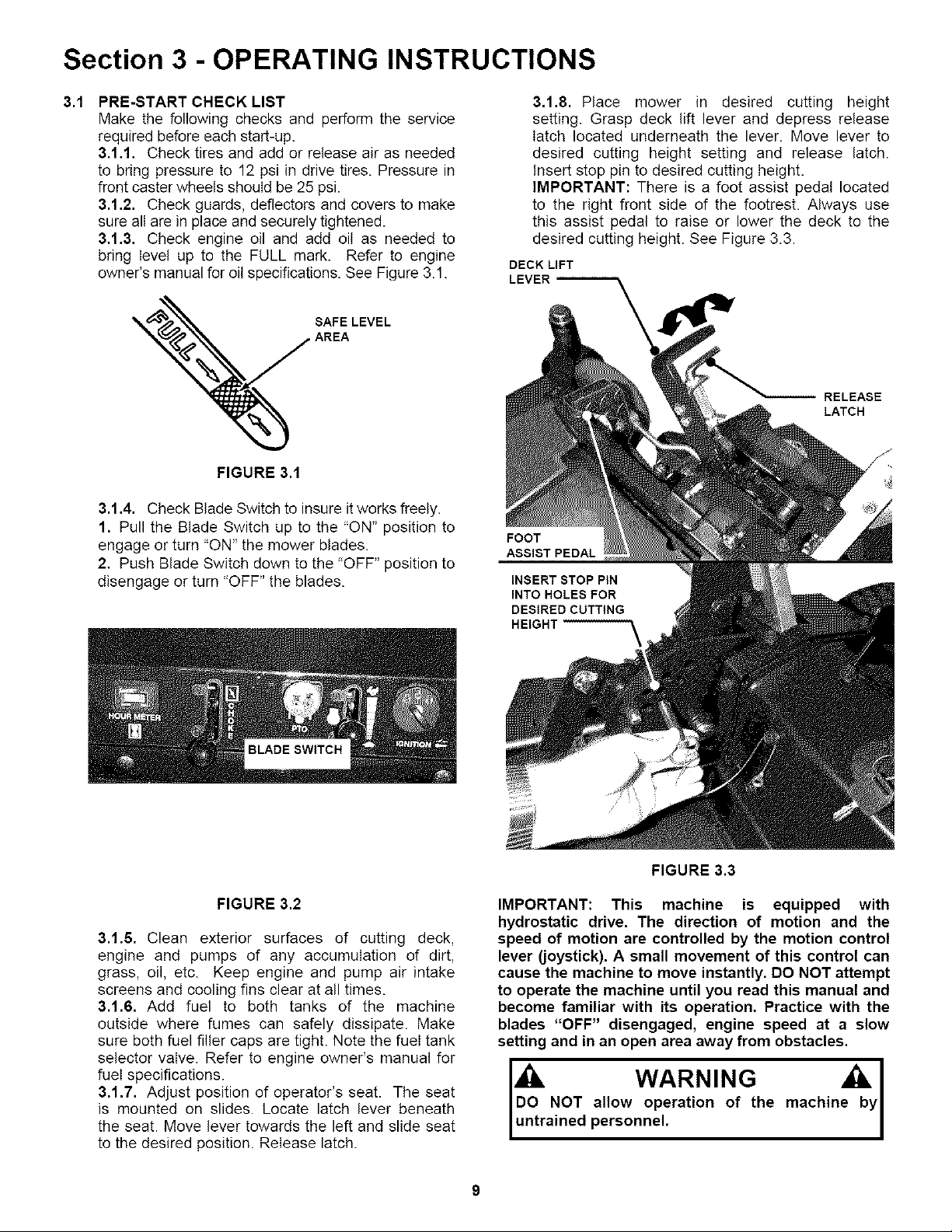
3,1,8. Place mower in desired cutting height
setting. Grasp deck lift lever and depress release
latch located underneath the lever. Move lever to
desired cutting height setting and release latch.
Insert stop pin to desired cutting height.
IMPORTANT: There is a foot assist pedal located
to the right front side of the footrest. Always use
this assist pedal to raise or lower the deck to the
desired cutting height. See Figure 3.3.
DECK LIFT
LEVER
RELEASE
LATCH
FOOT
ASSIST PEDAL
INSERT STOP PIN
INTO HOLES FOR
DESIRED CUTTING
HEIGHT
FIGURE 3.2
3.1.6. Clean exterior surfaces of cutting deck,
engine and pumps of any accumulation of dirt,
grass, oil, etc. Keep engine and pump air intake
screens and cooling fins clear at all times.
3.1.6. Add fuel to both tanks of the machine
outside where fumes can safely dissipate. Make
sure both fuel filler caps are tight. Note the fuel tank
selector valve. Refer to engine owner's manual for
fuel specifications.
3.1.7. Adjust position of operator's seat. The seat
is mounted on slides. Locate latch lever beneath
the seat. Move lever towards the left and slide seat
to the desired position. Release latch.
FIGURE 3.3
IMPORTANT: This machine is equipped with
hydrostatic drive. The direction of motion and the
speed of motion are controlled by the motion control
lever (joystick). A small movement of this control can
cause the machine to move instantly. DO NOT attempt
to operate the machine until you read this manual and
become familiar with its operation. Practice with the
blades "OFF" disengaged, engine speed at a slow
setting and in an open area away from obstacles.
allow operation of the machin
personnel.

Section 3 - OPERATING INSTRUCTIONS
ROLL RELEASE: To roll the machine without the
engine running, pressure within the hydraulic pumps
must be released, There is a hydraulic pressure relief
valve on the upper side of each pump that is used to
release the pressure. Use awrench to rotate both relief
valves counter clockwise two full turns to open, After
rolling machine, both relief valves must be rotated
clockwise to close valves and tighten securely before
operating machine, Machine will not move if relief
valves are open, See Figure 3.3.
3.2 STARTING & STOPPING - ENGINE, BLADES,
PARKING BRAKE
This machine is equipped with dual hydraulic pumps and
wheel drive motors. Each pump is controlled by a single
motion control lever or joystick. This single control lever
(joystick) controls the direction of motion, Forward and
Reverse, and the speed of motion. Move the joystick
forward to propel the machine forward. Move the control
rearward to propel the machine in reverse. The speed of
motion is continuously variable from neutral (zero) to
maximum. Moving the joystick farther from the neutral
position will cause the speed of motion to increase. To
turn, move the joystick towards the side you want to turn
to. DO NOT make sudden changes in speed or
direction. Always slow machine motion before turning.
To stop the motion of the machine, bring the joystick
back to the neutral position. Engage parking brake.
3.2.1. STARTING ENGINE
When the ignition key is turned the engine will not
start or turn over unless, the blade switch is pushed
in to the "OFF" position, the motion control lever is
in the neutral position with the parking brake
engaged.
1, Complete pre-start checklist.
2, Sit in operator's seat.
3, Push blade switch in to "OFF", blades
disengaged position and engage parking brake.
See Figures 3.2 and 3.7.
4, Move choke control forward to choke position to
start a cold engine. See Figure 3.5.
5, Move engine speed control to the Rabbit "FAST"
position. See Figure 3.5.
6, Turn key to the start position until engine starts.
See Figure 3.6.
WARNING
DO NOT disengage the hydro transmission and coast
down slopes. DO NOT use Roll Release Control to
disengage the hydro transmission unless machine
motion can be controlled and engine is off.
CHOKE SPEED
SHOWN FROM OPERATOR'S VIEW POINT
10
ENGINE
KEY
SWITCH
FIGURE 3.5
 Loading...