

Page 1
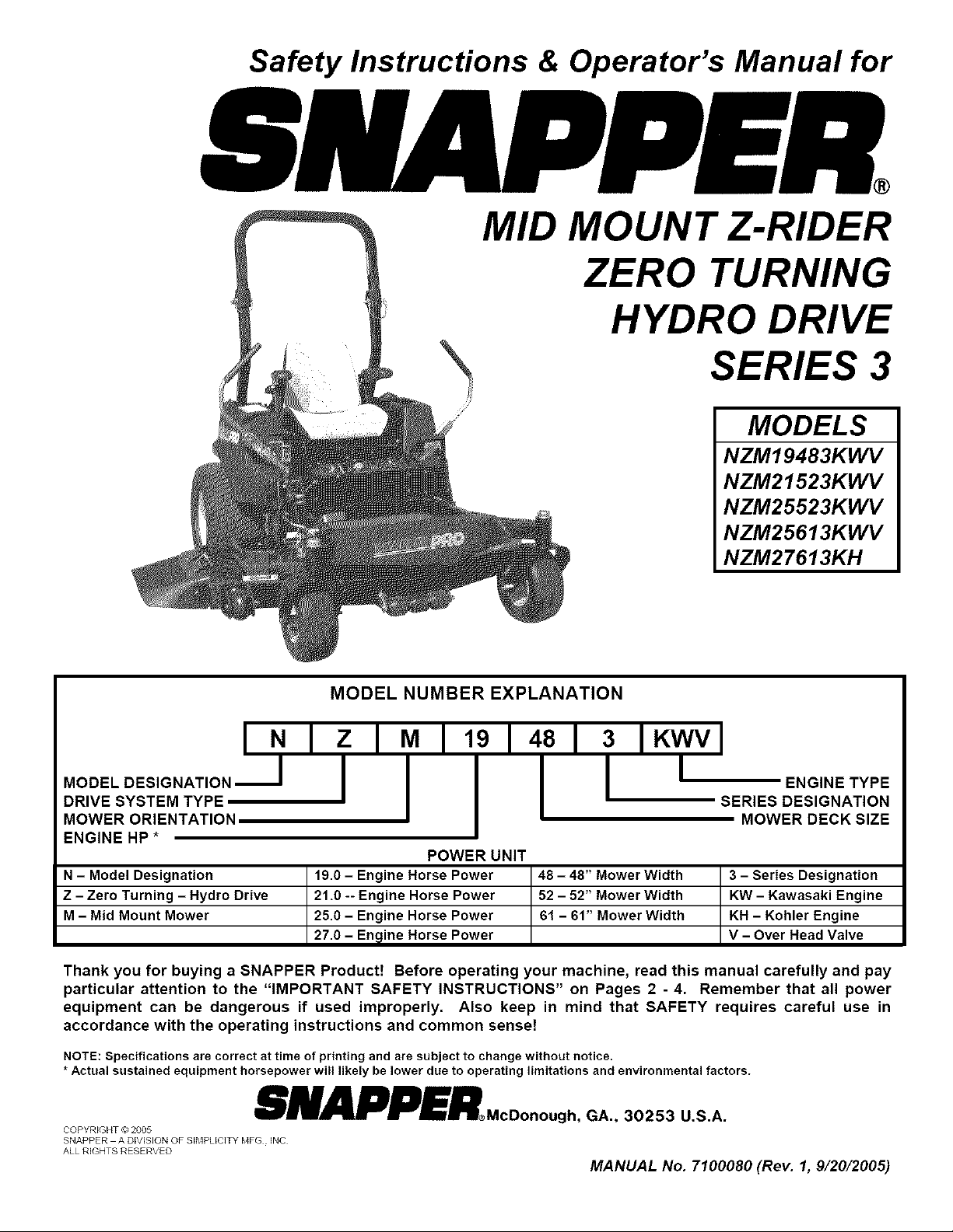
Safety Instructions & Operator's Manual for
MID
MOUNT Z-RIDER
ZERO TURNING
HYDRO DRIVE
SERIES 3
MODELS
NZM19483KWV
NZM21523KWV
NZM25523KWV
NZM25613KWV
NZM27 613KH
MODEL NUMBER EXPLANATION
INI ;
MODEL DESIGNATION ._1
DRIVE SYSTEM TYPE
MOWER ORIENTATION
ENGINE HP *
N - Model Designation 48 - 48" Mower Width 3 - Series Designation
Z - Zero Turning - Hydro Drive 52 - 52" Mower Width KW - Kawasaki Engine
M - Mid Mount Mower 61 - 61" Mower Width KH - Kohler Engine
Thank you for buying a SNAPPER Product! Before operating your machine, read this manual carefully and pay
particular attention to the "IMPORTANT SAFETY INSTRUCTIONS" on Pages 2 - 4. Remember that all power
equipment can be dangerous if used improperly. Also keep in mind that SAFETY requires careful use in
accordance with the operating instructions and common sense!
NOTE: Specifications are correct at time of printing and are subject to change without notice.
* Actual sustained equipment horsepower will likely be lower due to operating limitations and environmental factors.
:1 I1I 1_1431 : IKWVl
POWER UNIT
19.0 - Engine Horse Power
21.0 -- Engine Horse Power
25.0 - Engine Horse Power
27.0 - Engine Horse Power
I ENGINE TYPE
SERIES DESIGNATION
MOWER DECK SIZE
V - Over Head Valve
SNAPPER.coonougho.,3o2 3os.
COPYRIGHT (_ 2005
SNAPPER A DIVISION OF SIIqPLIO]TY _'TFG INC
ALL RIGHTS RESERVED
MANUAL No. 7100080 (Rev. I, 9/20/2005)
Page 2
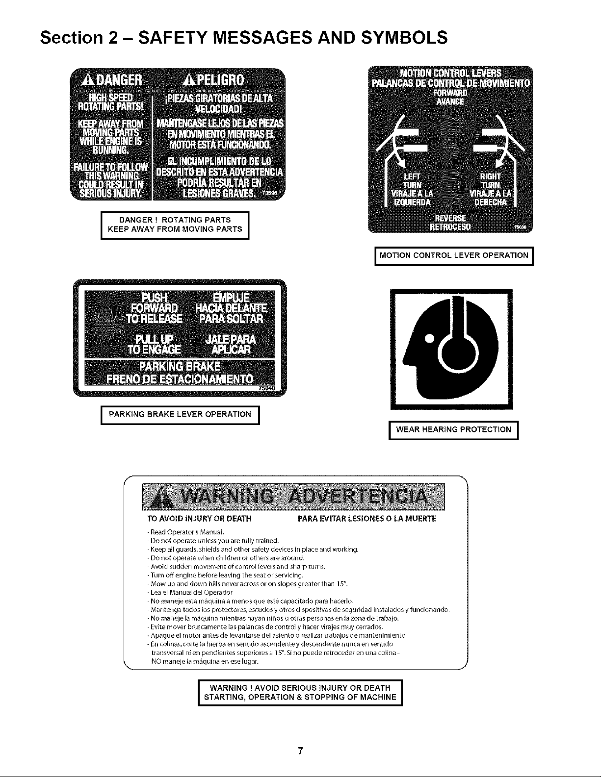
Section 2 - SAFETY MESSAGES AND SYMBOLS
KEEP AWAY FROM MOVING PARTS
I DANGER ! ROTATING PARTS I
I MOTION CONTROL LEVER OPERATION I
I PARKING BRAKE LEVER OPERATION I
f
TO AVOID INJU RY OR DEATH PARA EVITAR LESIONES O LA MUERTE
-Read Operator's Manual
Do not operate unless you ame fully tRained.
-Keep all guard s,shields and othel satety devices in place and wol king.
-DO not operate when children o_ others ale aiolJnd
Avoid sudden movement of control {evers alld shal p turns
Turn off engine betore leaving the seat or servicing.
Mow up and down hills nevel acloss or on slopes greater than I _ .
-Lea el Manual del Operador
-No maneje esta m_quina a mehos gue est_ capacitado paia hacello,
Mantenga todos los protector es,escudos y otros dispositivos de seguHdad instalados y funcionando
NO maneje la illaquilla m[entras Ilayan nihos u otras personas ell la zona de tlabajo,
Evite mover bruscamente las palancas de control y hater virajes muy cerrados
-Apague el motor antes de lewntarse del asiento o realizar trabajos de mantenimiemo
- En colinas, torte {a hier ba ell seflt[do ascende_lte y descendente iiuiica en _lllido
tl ansversal nien pehdientes sup_doLs a 15. Si no puede letrocede[ ell u{la co{ina
NO maneje lam_quina en ese lugal.
\
STARTING, OPERATION & STOPPING OF MACHINE
I WARNING ! AVOID SERIOUS INJURY OR DEATH I
I WEAR HEARING PROTECTION I
J
i
I
Page 3
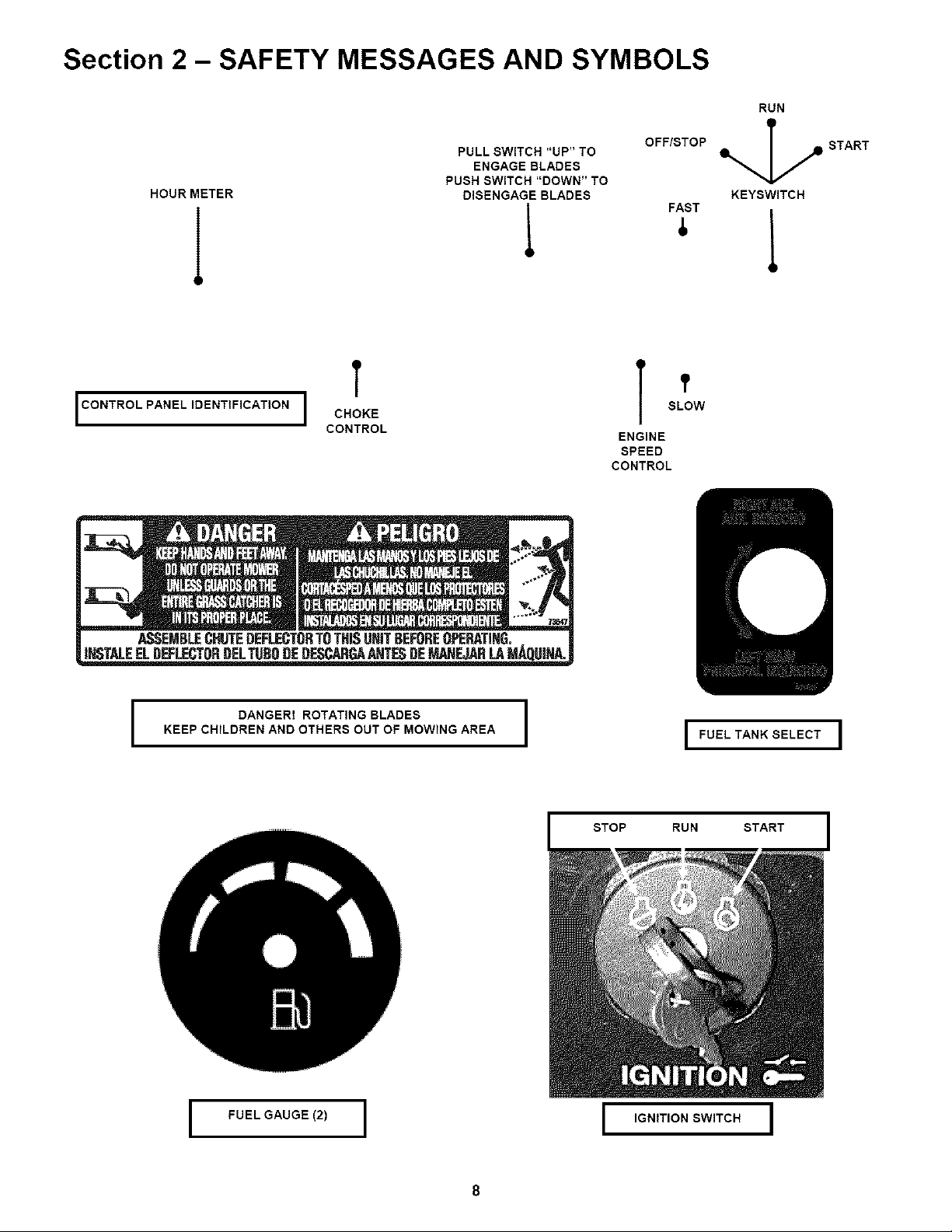
Section 2 - SAFETY MESSAGES AND SYMBOLS
RUN
HOUR METER DISENGAGE BLADES
I CONTROL PANEL IDENTIFICATION I
T
CHOKE
CONTROL
PULL SWITCH "UP" TO
ENGAGE BLADES
PUSH SWITCH "DOWN" TO
OFF/STOP
T TSLOW
ENGINE
SPEED
CONTROL
START
KEYSWITCH
FAST
DANGER! ROTATING BLADES
KEEP CHILDREN AND OTHERS OUT OF MOWING AREA
STOP RUN START
I
I FUELGAUGE(2) I I IGNITION SWITCH I
I FUEL TANK SELECT I
Page 4
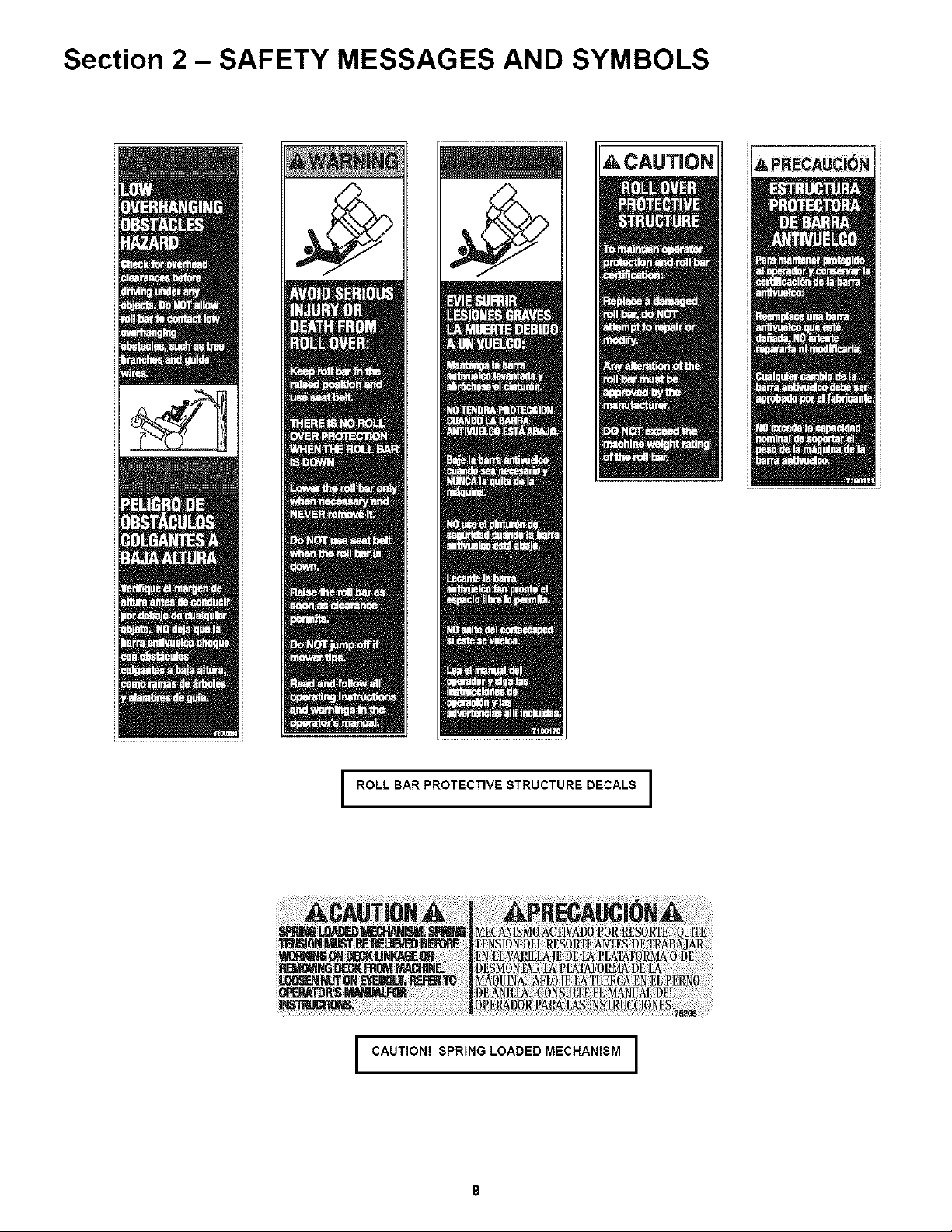
Section 2 - SAFETY MESSAGES AND SYMBOLS
I ROLL BARPROTECTIVESTRUCTUREDECALS I
I CAUTION! SPRING LOADED MECHANISM I
Page 5
Section 3 - OPERATING INSTRUCTIONS
3.1 PRE-START CHECK LIST
Make the following checks and perform the service
required before each start-up.
3.1.1. Check tires and add or release air as needed
to bring pressure to 12 psi in drive tires. Pressure in
front caster wheels should be 25 psi.
3.1.2. Check guards, deflectors and covers to make
sure all are in place and securely tightened.
3.1.3. Check engine oil and add oil as needed to
bring level up to the FULL mark. Refer to engine
owner's manual for oil specifications. See Figure 3.1.
FIGURE 3.1
3.1.4. Check Blade Switch to insure it works freely.
1. Pull the Blade Switch up to the "ON" position to
engage or turn "ON" the mower blades.
2. Push Blade Switch down to the "OFF" position to
disengage (or turn "OFF") the blades.
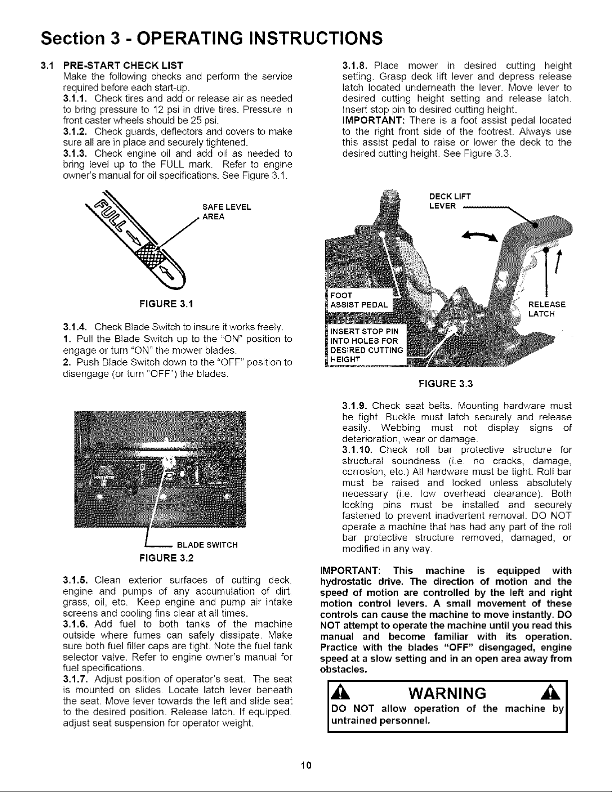
3.1.8. Place mower in desired cutting height
setting. Grasp deck lift lever and depress release
latch located underneath the lever. Move lever to
desired cutting height setting and release latch.
Insert stop pin to desired cutting height.
IMPORTANT: There is a foot assist pedal located
to the right front side of the footrest. Always use
this assist pedal to raise or lower the deck to the
desired cutting height. See Figure 3.3.
DECK LIFT
LEVER
RELEASE
LATCH
HEIGHT
FIGURE 3.3
BLADESWITCH
FIGURE 3.2
3.1.6. Clean exterior surfaces of cutting deck,
engine and pumps of any accumulation of dirt,
grass, oil, etc. Keep engine and pump air intake
screens and cooling fins clear at all times.
3.1.6. Add fuel to both tanks of the machine
outside where fumes can safely dissipate. Make
sure both fuel filler caps are tight. Note the fuel tank
selector valve. Refer to engine owner's manual for
fuel specifications.
3.1.7. Adjust position of operator's seat. The seat
is mounted on slides. Locate latch lever beneath
the seat. Move lever towards the left and slide seat
to the desired position. Release latch. If equipped,
adjust seat suspension for operator weight.
3.1.9. Check seat belts. Mounting hardware must
be tight. Buckle must latch securely and release
easily. Webbing must not display signs of
deterioration, wear or damage.
3.1.10. Check roll bar protective structure for
structural soundness (i.e. no cracks, damage,
corrosion, etc.) All hardware must be tight. Roll bar
must be raised and locked unless absolutely
necessary (i.e. low overhead clearance). Both
locking pins must be installed and securely
fastened to prevent inadvertent removal. DO NOT
operate a machine that has had any part of the roll
bar protective structure removed, damaged, or
modified in any way.
IMPORTANT: This machine is equipped with
hydrostatic drive, The direction of motion and the
speed of motion are controlled by the left and right
motion control levers, A small movement of these
controls can cause the machine to move instantly. DO
NOT attempt to operate the machine until you read this
manual and become familiar with its operation,
Practice with the blades "OFF" disengaged, engine
speed at a slow setting and in an open area away from
obstacles.
allow operation of the machin
w.....o
personnel.
10
Page 6

Section 3 - OPERATING INSTRUCTIONS
3,4,2, STOPPING MACHINE
1, Return motion controt lever to the neutral
position & the neutral lock position.
IMPORTANT: Operator must use hand assistance
to bring both motion control levers to the neutral
position & the neutral lock position.
MOTION
CONTROL
LEVER
NEUTRAL
LOCK
POSITION
FIGURE 3.13
2. Engage parking brake.
3. Push Blade Switch down to the "OFF" position
to disengage or turn "OFF" the blades.
4. Stop engine. Move engine speed control to
turtle "SLOW" position. Turn key to stop position.
5. Remove key.
DO NOT park the machine on slopes, DO NOT
machine with engine running, Stop engine.
WARNING
blades, Engage parking brake, Remove key,
3.5 FOLDING THE ROLL BAR PROTECTIVE
STRUCTURE
The roll bar protective structure should be folded ONLY
when absolutely necessary - i.e. when there is low
overhead clearance. NEVER remove any part of the
structure. To fold:
1. Shut off engine and remove key.
2. Loosen star knobs and remove locking pins. See
Figure 3.14.
3. Fold roll bar down against backs of side bars.
4. Tighten star knobs and replace pins to prevent loss.
LOOSEN
STAR
FOLD
ROLL
BAR
KNOBS &
REMOVE
LOCKING
FIGURE 3.14
5. Raise and lock roll bar as soon as clearance permits.
IMPORTANT: DO NOT use seat belt when roll bar is
folded.
no roll-over protection when roll b
3.6 SAFETY INTERLOCK SYSTEM CHECKS
This machine is equipped with an electrical safety
interlock system that is provided for the safety of the
operator and others. All safety devices must be in place
and functioning properly before operating the machine.
Perform the following interlock system checks
periodically during the operating season. Contact your
authorized Snapper dealer if you have questions.
WARNING
DO NOT operate machine if any safety interlock or
safety device is not in place and functioning
properly. DO NOT attempt to defeat, modify or
remove any safety device.
ENGINE MUST NOT START IF:
1. Motion Control Lever(s) are not in the neutral
lock position OR,
2. Parking Brake disengaged and Operator not
seated in the Operator's Seat OR,
3. Blade Switch in the "ON" blades engaged
position.
ENGINE SHOULD START IF:
1. Blade Switch in the "OFF" blades disengaged
position AND,
2. Motion Control Levers are both in the neutral
lock position AND,
3. Operator properly seated in the Operator's Seat
OR,
4. Parking Brake engaged.
NOTE: The engine can be started with the parking
brake disengaged only if conditions in 1, 2 and 3
have been met.
ENGINE MUST BEGIN TO STOP IF:
1. Motion Control Levers are moved from the
neutral lock position with Parking Brake
engaged OR,
2. Operator rises off of seat with Blade Switch in
"ON" blades engaged position OR,
3. Operator rises off of seat with Parking Brake
disengaged.
IMPORTANT: Engine and blades will continue to
run if Operator becomes reseated prior to engine
coming to a complete stop. After coming to a
complete stop, the blade switch must be moved to
the "OFF" position before engine can be restarted.
Engine and blades must come to a complete stop
within 7 seconds after the operator rises off the seat
or the blade switch is moved to the "OFF" position.
14
Page 7

Section 4 - MAINTENANCE
WARN ING
Allow engine to cool for at least ten minutes before
performing service or maintenance. DO NOT smoke
near fuel components when performing service or
maintenance. DO NOT perform service and
maintenance near an open flame. Wipe off any
spilled fuel before starting engine. DO NOT run
engine indoors.
4.5 ANNUALLY (END OF EACH SEASON)
(Continued from previous Page)
4,5,2. FUEL FILTER
Service fuel filter as instructed below. Turn key to
"OFF" position. Engine MUST be stopped and
MUST be cold before removing filter. Clamp fuel line
to prevent fuel spillage or perform filter change when
fuel tank and fuel line are empty.
1. Remove fuel line clamps from fuel filter.
2. Remove fuel lines from filter. Discard filter.
3. Install new fuel filter. IMPORTANT: Some fuel
filters are fuel flow directional. Check for arrow that
shows fuel flow direction. Reinstall fuel Iine clamps.
See Figure 4.8.
LEFT SIDE OF
MACHINE
4.6 DECK REMOVAL
Move power unit/mower deck to an area where the
mower deck is to be disconnected. Turn engine
"OFF" and remove key from switch. Remove spark
plug wire(s) and secure away from spark plug(s).
Move motion control levers to the neutral position.
Engage parking brake.
1. Move deck lift lever and set the mower deck to
the highest cutting position. See Figure 4.9.
2. IMPORTANT - STORED ENERGY, Relieve
tension on deck lift assist spring by backing off nut
on eyebolt. Failure to relive tension could result in
personal injury. See Figure 4.9.
3. Place a wooden block under the front and rear
edge of the mower deck.
4. Move deck lift lever and set the mower deck to a
lower cutting position until deck rests on wooden
blocks. Position the deck to where there is no
tension on the deck hanger chains. See Figure 4.9.
LOWEST CUTTING
POSITION (ALL THE
WAY ,)
CLAMP FUEL LINE
TO PREVENT
REMOVE LINE
CLAMPS SPILLAGE
LINE TO
PREVENT
FIGURE 4.8
POSITION DECK LIFT LEVER IN HIGHEST CUTTING
POSITION. PLACE WOODEN BLOCKS UNDER FRONT
AND REAR OF DECK, LOWER DECK ONTO BLOCKS
LOOSEN DECK
LIFT ASSIST
FIGURE 4.9
(Continued On Next Page)
18
Page 8

Section 5 - ADJUSTMENTS & REPAIR
Ik DANGER
Exercise EXTREME CAUTION when making this I
adjustment, due to close proximity of moving parts. I
5.1 NEUTRAL POSITION ADJUSTMENTS
The motion control levers control the movement
and stopping of the machine. Move the control
levers to the center or neutral position to stop
machine.
IMPORTANT: Always return both motion control
levers with hand assistance to the neutral
position, If machine does not come to a
complete stop or machine has movement when
control levers are moved to the neutral lock
position, adjustment must be made.
1. Turn key to "OFF" position.
2. Move motion control levers to the neutral lock
position. Refer to Figure 3.7.
3. Raise both rear wheels off the ground. Secure
machine with safety blocks.
4. Remove cover screen to expose top of hydro
pumps and linkages. See Figure 5.1.
5. Remove both fans from top of hydro pumps.
6. Disconnect motion lever connecting rods from
hydro pump activation assembly. See Figure 5.2.
!REMOVESCREEN
REMOVE MOTION CONTROL
LEVER CONNECTING ROD
HYDRO PUMP
ACTIVATION
ASSEMBLY
FIGURE 5.2
MOVE ACTIVATION
ASSEMBLY
REARWARD OR
FORWARD TO ACHIEVE
FIGURE 5.1
7. Turn key to start position and start machine.
Move engine speed control to the Rabbit "FAST"
position
8. Disengage parking brake.
9. Both wheels should not have any movement, not
rotating.
10. If wheel(s) are rotating, loosen the hydro pump
activation assembly retaining screw. Move activation
assembly forward or rearward to stop rotation of
wheel. Retighten retaining screw. Repeat this step for
other hydro pump. See Figure 5.3.
11. Stop engine.
LOOSEN ACTIVATION
ASSEMBLY RETAINING
SCREW
FIGURE 5.3
(Continued On Next Page)
20
Page 9

Section 5 - ADJUSTMENTS & REPAIR
5.1 NEUTRAL POSITION ADJUSTMENTS 5.2
(Continued From Previous Page)
12, With motion control levers remaining in the
neutral lock position, See Figure 3.7, hold connecting
rod up to the activation assembly and check length of
rod. Tie rod end bolt must align with the activation
assembly. If bolt is not aligned with the activation
assembly, adjust tie rod. Loosen jam nut that secures
tie rod. Rotate tie rod in or out to align with hole in
activation assembly. Repeat step for other hydro
pump. See Figure 5.4.
HYDROPUMP!ill: HYDRO
ACTIVATION PUMP
ASSEMBLY
TIE ROD END
BOLT IS SHOWN
MISALIGN WITH
ACTIVATION
ASSEMBLY
LOOSEN NUT AND
ROTATE TIE ROD END
TIE ROD END
IN OR OUT TO ALIGN
WITH ACTIVATION
MOWER DECK & COMPONENT ADJUSTMENTS
The leveling procedures for the 61 deck differ from
the 48 and 52 decks. The 61 deck replaces the two
rear eyebolts with slotted brackets_ and uses 1 1/4"
leveling blocks in place of the 1_'blocks. Follow and
complete each step carefully.
5,2.1, MOWER DECK ADJUSTMENT (LEVELNESS)
SIDE to SIDE and FRONT to REAR
Before making deck leveling adjustments, inflate rear
tires to 12 PSI and front tires to 25 PSI. When
adjusted correctly, the deck will be level side to side
within 1/8", have a low cut setting of approximately 1"
(1 1/4" for 61 deck) and the blades pitched
approximately 3/16" higher at the rear.
1. Place machine on a smooth level surface.
2. Check side to side level by rotating blades until
tips are pointing to the sides of the deck. Check the
measurement of outside blade tips to the ground on
both blades. The measurement of each of the outside
blade tips should be within 1/8" of each other. If
measurement of the blade tips is not within 1/8",
adjustment should be made.
3. Move deck lift lever and set the mower deck to the
highest cutting position.
4. Relive tension on deck lift assist spring by
loosening nut on eyebolt. Refer to Section
"Removing Deck".
5. Place 1" blocks (1 1/4" for 61 deck) under the front
and rear edge of the mower deck.
6. Move deck lift lever and set the mower deck to the
lowest cutting position.
6. Loosen the nuts and bolts that secure both front
deck support chains. Adjust chains until tight and
retighten bolts and nuts. Torque to 20 to 30 ft. Ibs.
See Figure 5.5.
BOLT IS SHOWN
ALIGNED WITH
HOLE
FIGURE 5.4
13. Once tie rod end bolt is aligned with activation
assembly insert into hole and reinstatI washers and
nut that secure bolt to assembly. Tighten securely.
Tighten tie rod jam nut securely.
14. Start engine, disengage parking brake, and
check rotation of the rear wheels.
15. Reinstall both hydro pump fans. Reinstall
washer and bolt. Tighten bolt securely.
16. Reinstall screen and tighten retaining hardware
securely.
FRONT
LIFT ARM
DECK HANGER
BRACKET
LOOSEN BOLT AND NUT,
TIGHTEN CHAIN. SECURE
BOLTS AND NUTS
FIGURE 5.5
21
Page 10

Section 5 - ADJUSTMENTS & REPAIR
WARNING
DO NOT attempt any maintenance, adjustments or
service with engine running. STOP engine. STOP
blades. Set brake. Remove key. Remove spark plug
wires and secure away from spark plugs. Engine
and components are HOT. Avoid serious burns,
allow sufficient time for all parts to cool.
5.3 TRACTION BELT TENSION
The traction drive belt tension does not require
adjustment. If the belts are slipping, they will have to be
replaced.
LOCK NUT
J-BOLT
FIGURE 5.9
5.4 TRACTION BELT REPLACEMENT
1. Remove clutch to deck belt• See Figure 5.10•
2. Turn lock nut out to the end of J-Bolt, reducing
spring tension• Unhook traction idler spring from bolt
in frame• See Figure 5.9
3. Remove anti-rotation bracket. See Figure 5.10
4. Disconnect the electric clutch from main wire
harness.
5, Remove traction belts from around engine pulley
and hydro pumps.
6, Install new belts and route around engine pulley
and hydro pump pulleys.
7, Reconnect electric clutch to main wire harness.
8, Reinstall anti-rotation bracket and tighten nuts
securely.
9, Reattach traction idler spring. Run lock nut all
the way to the end of the threads on the J-Bolt.
See Figure 5.10.
10. Reinstall electric clutch to deck belt onto
electric clutch.
UNHOOK TRACTION
DRIVE IDLER SPRING
REMOVECLUTCH
TO DECK BELT
REMOVEANTI-
ROTATION BRACKET
FIGURE 5.10
5.5 BLADE BRAKE/ELECTRIC CLUTCH ADJUSTMENT
The blade switch engages the electric clutch when
pulled out to the "ON" position• When the blade
switch is in the "ON_' position the cutting blade(s)
are engaged• The blade switch disengages the
electric clutch when the blade switch is pushed in
to the "OFF" position. When the blade switch is in
the "OFF" position the cutting blade(s) are
disengaged. The electric clutch is adjustable• The
blades should stop rotation in 7 seconds or less• If
the electric clutch fails to stop the blades rotation in
7 seconds, adjustment is necessary.
1. Insert a feeler gauge into the three slots on the
electric clutch•
2. Check gap through all three slots in the side of
the clutch. The gap should be set at .015•
3. If gap is incorrect rotate nuts in or out to achieve
the correct gap. See Figure 5.11.
NOTE: Electric Clutch is shown removed from the
machine• Removal is not necessary for adjustment•
GAP SHOULD BE .015
f
H
ROTATE NUTS
IN OR OUT
TO ACHIEVE
CORRECTGAP
23
FIGURE 5.11
Page 11

Section 5 - ADJUSTMENTS & REPAIR
5.6 TRACKING ADJUSTMENT
If the machine does not track straight when the
Motion Control Levers are in the maximum forward
speed position, perform the following adjustment.
Rear tire pressure must be set to 12 PSi before
making this adjustment.
1. Loosen bolts that secure adjustment plates and
slide plates all the way forward. Retighten bolts.
2. Start machine and drive in smooth flat open area
at maximum forward speed.
3. If machine tracks to the right, loosen bolts that
secure the left adjustment plate. Move plate
rearward to slow the left wheel. Retighten bolts.
4. If machine tracks to the left, loosen bolts that
secure the right adjustment plate. Move plate
rearward to slow the right wheel down. Retighten
bolts. See Figure 5.12.
5. Drive machine again. Repeat adjustment as
necessary until machine tracks straight.
LOOSEN BOLTS.
SLIDE PLATE TO
MAKE MACHINE
TRACK STRAIGHT
5.7 MOWER DRIVE BELT REPLACEMENT
Inspect mower drive belt. Replace belt if it shows
signs of excessive wear, damage and/or is broken.
5.7.1. BELT REMOVAL
1. Remove power unit footrest.
2. The engine to deck belt must be removed before
the deck belt can be removed. Remove engine to
deck belt.
3. Disconnect deck belt tension spring.
4. Remove old deck belt. Note the belt routing. See
Figure 5.12.
5.7.2. BELT REPLACEMENT
1. The deck belt must be installed first and the
engine to deck belt installed last.
2. Route deck belt around blade pulleys and idler
pulley in the same position as old belt was
removed. See Figure 5.13.
3. Reconnect idler pulley spring.
4. Reinstall engine to deck belt.
5. Reinstall power unit footrest.
RIGHT
FIGURE 5.12
DECK
BELT
ELECTRIC
CLUTCH 7
ENGINE TO
DECK BELT
LEFT
BELT ROUTING
24
FIGURE 5.13
Page 12

Section 5 - ADJUSTMENTS & REPAIR
5.11 MOWER SPINDLES (Field Serviceable Spindles)
BEARING REPLACEMENT
In the event that a spindle bearing requires
replacement, the SNAPPER Field Serviceable
Spindles have been designed so that no special
tools or presses are required.
1. Remove belt. Loosen blade nut and remove.
Allow blade bolt, washer_ blade and four spacers
to drop down out of the spindle housing. See
Figure 5.19.
REMOVE NUT
• REMOVE BELT
FROM SPINDLE
J
r !_ ;_M_VE BLADE
FIGURE 5,19
2. Remove spindle pulley from spindle shaft.
3. Locate circular retaining ring on spindle shaft at
top bearing. Remove retaining ring. Allow spindle
shaft to drop out of housing.
4. Top and bottom bearings are now removable.
Pull out on inner race to slide bearing from
housing. See Figure 5.20.
5. Thoroughly clean all parts removing all old
contaminated grease.
6. Install new bottom bearing first.
7. NOTE: The bearing is sealed/shielded on one
side only. The bottom bearing must be installed
with the sealed/shielded side DOWN.
8. Insert spindle shaft up through the bottom
bearing. Slide spacer down over spindle shaft.
9. Install new top bearing. Install the top bearing
with the seal/shield UP.
10. Slide circular retaining ring down spindle shaft
until it fully locks into groove on shaft.
11. Apply a generous amount of general-purpose
grease to the concave side of the nylos seal.
Install the nyIos seal with concave greased side
down.
12. Place spindle pulley and spacer on top of
spindle shaft.
13 ReinstaII blade bolt, washer, blade and four
spacers. See Figure 5.15
14. Torque blade bolt and nut to 70 to 80 ft. Ibs.
15. Pump grease into spindle housing until grease
purges from vent on housing.
16. After the first 5 hours of operation, grease
spindle housing to insure it is full, then every 25
hours.
IMPORTANT: Spindle housing must be filled with
grease before operating mower. Failure to fill
housing will cause premature bearing failure.
®
•_PULLEY
_1 SPACER
• NYLOS SEAL
i BEARING l _ C%" RETAINING RING
SEAL UP _L._t BEARING
HOUSING
SPINDLE
{_1" SPACER
DOWN • BEARING
I BEARING SEAL I
SHAFT
SPINDLE
FIGURE 5.20
28
Page 13

Section 5 - ADJUSTMENTS & REPAIR
5.12 HYDRAULIC SYSTEM, PURGING
After replacing or repairing hydraulic system
components, one or both of the wheel drives may
not pull properly. This is likely to be caused by air
entrapped in the system. If you experience a
pulling issue after completing repairs, perform the
following procedure to purge the air from one or
both of the hydraulic drive systems.
IMPORTANT: WHEN REPLACING THE HYDRAULIC
FLUID FILTERS, PRE-FILL BOTH WITH OIL
(SAE 20W50 API SL) BEFORE INSTALLING.
PRE-FILLING THE FILTERS WITH OIL WILL
REDUCE OR POSSIBLY ELIMINATE THE NEED
TO PURGE THE SYSTEM OF ENTRAPPED AIR
1. Locate hydraulic reservoir underneath
operator's seat. After thoroughly cleaning the area
around the top of the reservoir, remove filler cap.
Bring fluid to proper level (1 ½" below the top of
the filler neck). With engine off, add SAE 20W50
automotive oil. See Figure 4.6.
2. Open pressure relief valve on hydraulic pump,
turning counter clockwise 2 full turns. See Figure
3.3.
3. Carefully raise the rear of the machine so the
wheels are off of the ground. Securely block the
machine to prevent it from falling.
4. While seated in the operator's position, start the
engine. Place engine speed control in FAST
position.
5. Release parking brake and move motion
control levers out of the neutral lock position.
6. Slowly move motion control levers to the full
forward and then to the full reward positions.
Repeat this process 6 times.
7. Stop engine and wait for all rotation to stop
before leaving the operator's position.
8. Close pressure relief valve on hydraulic pump,
turning clockwise. Tighten snuggly.
9. With pressure relief valve closed, repeat Steps
4 thru 7.
10. Remove blocks and lower rear of machine.
11. Check fluid level in reservoir. Add SAE 20W50
automotive oil as required to bring fluid level to 1
½" from top of filler neck. Do Not over fill.
12. Install and tighten filler cap.
29
Page 14

Safety Instructions & Operator's Manual for
MID MOUNT Z-RIDER
ZERO TURNING
HYDRO DRIVE
SERIES 3
IMPORTANT
Snapper products are built using engines that meet or exceed all applicable emissions requirements on the
date manufactured. The labels on those engines contain very important emissions information and critical
safety warnings. Read, Understand, and Follow all warnings and instructions in this manual, the engine
manual, and on the machine, engine and attachments. If you have any questions about your Snapper product,
contact your local authorized Snapper dealer or contact Snapper Customer Service at Snapper, McDonough,
GA. 30253. Phone: (1-800-935-2967).
_l_ WARNING
BATTERY POSTS, TERMINALS AND RELATED ACCESSORIES CONTAIN LEAD AND LEAD COMPOUNDS,
CHEMICALS KNOWN TO THE STATE OF CALIFORNIA TO CAUSE CANCER AND BIRTH DEFECTS OR
OTHER REPRODUCTIVE HARM. WASH HANDS AFTER HANDLING.
WARNING
ENGINE EXHAUST, SOME OF ITS CONSTITUENTS, AND CERTAIN VEHICLE COMPONENTS CONTAIN OR
EMIT CHEMICALS KNOWN TO THE STATE OF CALIFORNIA TO CAUSE CANCER OR OTHER
REPRODUCTIVE HARM.
SNAPPERo.coonouo ,
COPYRIGHT © 2005
SNAPPER A DIVISION OF SIMPLICITY _,'IFG INC
ALL RIGHTS RESERVED
GA., 30253 U.S.A.
MANUAL No. 7100080 (Rev. I, 9/20/2005)
40
 Loading...