

Page 1
Safety Instructions & Operator's Manual for
MID MOUNT Z-RIDER
ZERO TURNING
HYDRO DRIVE
SERIES 1
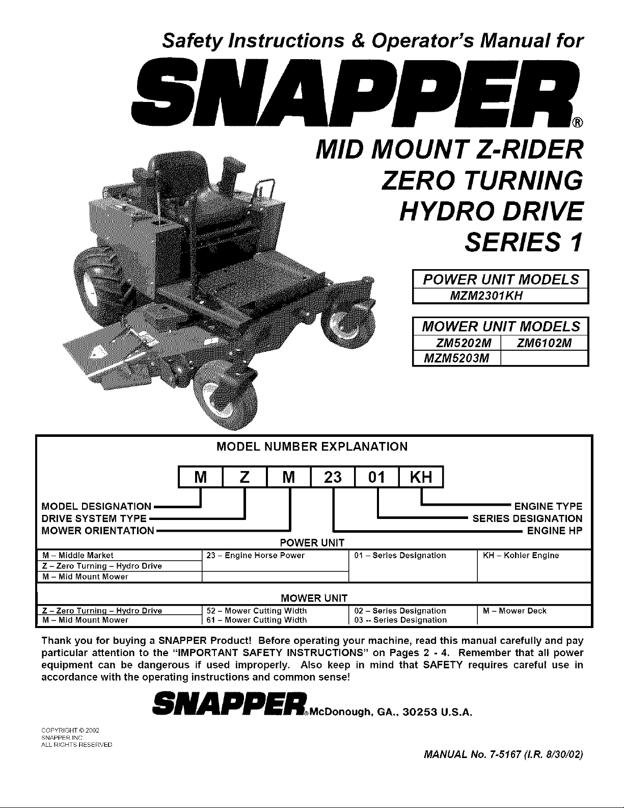
POWER UNIT MODEL S
MZM2301KH
MOWER UNIT MODEL S
ZM5202M ZM6102M
MZM5203M
MODEL NUMBER EXPLANATION
IMIZI_
MOOE'OES,GNAT,ON_I
DRIVE SYSTEM TYPE
MOWER ORIENTATION
M - Middle Market
Z - Zero Turning - Hydro Drive
M - Mid Mount Mower
Z - Zero Turninq - Hydro Drive
M - Mid Mount Mower
Thank you for buying a SNAPPER Product! Before operating your machine, read this manual carefully and pay
particular attention to the "IMPORTANT SAFETY INSTRUCTIONS" on Pages 2 - 4. Remember that all power
equipment can be dangerous if used improperly. Also keep in mind that SAFETY requires careful use in
accordance with the operating instructions and common sense!
23 - Engine Horse Power
52- Mower Cutting Width
61 - Mower Cutting Width
SNAPPER McDonough,
COPYRIGHT © 2002
SNAPPER INC
ALL RIGHTS RESERVED
_12
POWER UNIT
MOWER UNIT
310I lKHI
I
SERIES DESIGNATION
01 - Series Designation
I 02 - Series Designation I M - Mower Deck
03 -- Series Designation I
GA,, 30253 U.S.A.
MANUAL No. 7-5167 (I.R. 8/30/02)
ENGINE TYPE
ENGINE HP
KH - Kohler Engine
Page 2
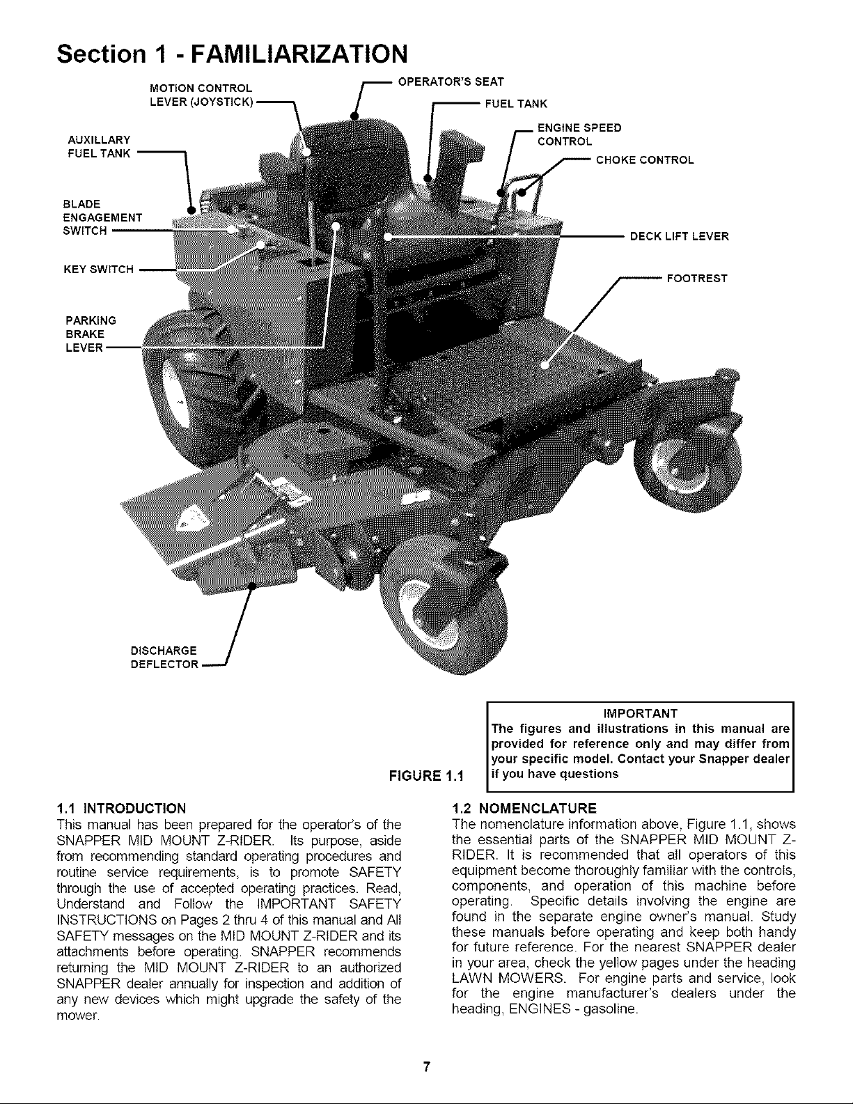
Section 1 - FAMILIARIZATION
AUXILLARY
FUEL TANK --
BLADE
ENGAGEMENT
SWITCH
PARKING
BRAKE
MOTION CONTROL
LEVER (JOYSTICK -- FUEL TANK
OPERATOR'S SEAT
ENGINE SPEED
CONTROL
DECK LIFT LEVER
FOOTREST
DISCHARGE
DEFLECTOR
FIGURE
1.1 INTRODUCTION
This manual has been prepared for the operator's of the
SNAPPER MID MOUNT Z-RIDER. Its purpose, aside
from recommending standard operating procedures and
routine service requirements, is to promote SAFETY
through the use of accepted operating practices. Read,
Understand and Follow the IMPORTANT SAFETY
INSTRUCTIONS on Pages 2 thru 4 of this manual and All
SAFETY messages on the MID MOUNT Z-RIDER and its
attachments before operating. SNAPPER recommends
returning the MID MOUNT Z-RIDER to an authorized
SNAPPER dealer annually for inspection and addition of
any new devices which might upgrade the safety of the
mower.
I IMPORTANT 1
The figures and illustrations in this manual areI
provided for reference only and may differ from I
your specific model. Contact your Snapper dealerI
1.1
if you havequestions I
1.2 NOMENCLATURE
The nomenclature information above, Figure 1.1, shows
the essential parts of the SNAPPER MID MOUNT Z-
RIDER. It is recommended that all operators of this
equipment become thoroughly familiar with the controls,
components, and operation of this machine before
operating. Specific details involving the engine are
found in the separate engine owner's manual. Study
these manuals before operating and keep both handy
for future reference. For the nearest SNAPPER dealer
in your area, check the yellow pages under the heading
LAWN MOWERS. For engine parts and service, look
for the engine manufacturer's dealers under the
heading, ENGINES - gasoline.
I
7
Page 3

Section 2 - SAFETY MESSAGES AND SYMBOLS
I BLAOBSENGAGBO"ON"I BLAOBSDISENGAGED"OFF"I
"START"
MOTION CONTROL
MULTI-DIRECTIONAL
BEFORE OPERATING
I READ OPERATOR'S MANUAL I
MACHINE
KEEP CHILDREN AND OTHERS OUT OF MOWING AREA
I DANGER! ROTATING BLADES
DANGER! ROTATING BLADES
9
Page 4

Section 4 - MAINTENANCE
4.3.3.
OIL FILL
LINE
RIDING MOWER - LUBRICATION
1. Front Wheel Bearings
Lubricate with Kendall NLGI No. 2 lithium
grease or equivalent, from a grease gun.
See Fi( 4.5.
FRONT
WHEE
FIGURE 4.5
2. Transaxle
Check the level of fluid in both of the fluid
reservoirs. Wipe away all dirt and debris from
around reservoir cap before removing. Oil
must remain absolutely clean! Check with
machine on a level surface with engine
"OFF". Fill reservoir as needed to bring
level up to 1-1/2 inches below the top of the
filler neck. Use clean, fresh premium
hydraulic oil having a viscosity equivalent to
SAE 20W20, SAE 30 or SAE40. The fluid
should be chemically stable, incorporating rust
and oxidation inhibitors. Make sure funnels,
pouring spouts and oil can are completely
clean. Reinstall reservoir cap. See Figure 3.6.
IMPORTANT: DO NOT remove or service
the transaxle fluid filters. This service should
be made periodically by an authorized
SNAPPER dealer. See the service schedule
to determine the recommended change
interval.
3. Power Transfer Shaft
Lubricate power transfer shaft with Kendall
NLGI No. 2 lithium grease or equivalent,
from a grease gun. See Figure 4.7.
VIEW IS SHOWN WITH
PARTS REMOVED FOR
CLEAR VIEW OF SHAFT
LUBRICATE
POWER
TRANSFER
FIGURE 4.7
4. Other Lubrication Points
Lubricate machine caster wheel shafts,
traction drive shaft and mower deck idler
arm with Kendall NLGI No. 2 lithium grease
or equivalent, from a grease gun.
4.4
BEFORE OPERATING MACHINE
1, Clean all dirt and debris from around the two
hydraulic fluid reservoirs. Especially around the top
and cap area.
2, Clean all dirt and debris from the cooling fins on
the engine and from both hydraulic pumps.
4.5
ANNUALLY (END OF EACH SEASON)
Perform aII maintenance as described in Section
"AFTER EVERY 25 OPERATING HOURS".
4.5.1. ENGINE
Service engine according to engine owner's manual.
HYDRAULIC OIL
RESERVOIR
(Continued on next Page)
IMPORTANT: FLUID LEVEL MUST
BE ABOVE TOP OF BAFFLE.
RESERVOIR CAPACITY IS ONE (1)
GALLON. DO NOT OVERFILL.
FIGURE 4.6
16
Page 5

Section 5 - ADJUSTMENTS & REPAIR
5.5.2. BLADE SHARPENING
1. Remove blade. See Figure 5.5.
®
BEVELED WASHER
FIGURE 5.5
BLADE
BLADE MOUNTING
BOLT
5.6 MOWER DRIVE BELT REPLACEMENT
Inspect mower drive belt. Replace belt if it shows
signs of excessive wear, damage and/or is broken.
5.6.1. BELT REMOVAL
1. Remove power unit foot rest.
2, Remove old belt.
5.6.2. BELT REPLACEMENT
1. Route belt around blade pulleys and idler
pulley in same the position as old belt was
removed. It may be necessary to use a pry
bar to pull idler pulley back to install belt.
See Figure 5.7.
2, Reinstall power unit foot rest.
2. Inspect condition of blade. See Figure 4.4.
3. If blade is in good condition, sharpen at 22
to 28 degrees. DO NOT sharpen beyond
original cutting edge. See Figure 5.6.
BLADE
22° TO 28°
ORIGINAL CUTTING EDGE
FIGURE 5.6
4. Check blade balance after sharpening.
If necessary, correct blade balance by
grinding the heavy end of blade.
IMPORTANT: Blade balancing should be performed by a
qualified dealer.
FRONT OFDECK
BELT
ROUTING
FIGURE 5.7
5. Reinstall blade. See Figure 5.5. Torque
blade mounting bolts to recommended
range of 70 to 80 ft. Ibs.
22
Page 6

Section 5 - ADJUSTMENTS & REPAIR
WARNING
Shield the positive terminal with terminal cover
located on battery harness. This prevents metal from
touching the positive terminal, which could cause
sparks. Cables must be connected to battery
terminals in the proper position. RED (Positive) cable
must go to the ( + ) terminal. BLACK (Negative) cable
must go to the ( - ) terminal.
5.7 BATTERY
5.7.1. BATTERY REMOVAL
1. Remove battery retainer.
2. Slide terminal cover away from positive
terminal.
3. Observe and note cable positions on
battery. See Figure 5.8.
4. Disconnect cables from battery terminals,
disconnecting BLACK (Negative) cable first,
then disconnect RED (Positive) last. Retain
mounting bolts and nuts.
RED (POSITIVE) CABLE
\
TERMINAL COVER
4. With celt caps removed, connect battery
charger to battery terminals. RED to positive
(+) terminal and BLACK to negative (-)
terminal.
5. Slow charge battery at 1 amp for 10
hours. An alternative fast charge should be
no more than 2.5 amps for four hours.
6. If battery will not accept charge or is
partially charged after 10 hours of charging
at 1 amp, replace with new battery.
CABLE
TERMINAL
COVER MUST
SHIELD
POSITIVE
TERMINAL
AFTER
INSTALLATION
5.7.2.
5.7.3.
BLACK (NEGATIVE)
CABLE
\
FIGURE 5.8
BATTERY INSTALLATION
1. Position battery into battery compartment.
2, Connect cables to battery terminals.
Connect RED (Positive) cable first. Connect
BLACK (Negative) cable last.
3, Reinstall battery retainer and positive
terminal cover. See Figure 5.9
BATTERY SERVICE
1. Remove battery.
2, Place battery in a well ventilated area on
a level surface.
3. Using distilled water, refill ceils as
required to cover ceil plates.
FIGURE 5.9
WARNING
The electrolyte (acid) produces a highly explosive
gas. Keep all sparks, flame and fire away from area
when charging battery or when handling electrolyte
or battery. Electrolyte (acid) is a highly corrosive
liquid. Wear eye protection. Wash affected areas
immediately after having eye or skin contact with
electrolyte (acid). Battery acid is corrosive. Rinse
empty acid containers with water and mutilate before
discarding. If acid is spilled on battery, bench, or
clothing, etc., Flush with clear water and neutralize
with baking soda.
23
Page 7

TROUBLESHOOTING
PROBLEM PROBABLE CAUSE CORRECTIVE ACTION
Starter Will Not Crank 1. Battery dead. 1. Service battery.
Engine 2. Blown fuse. 2. Replace fuse.
3. Electrical connections loose or corroded. 3. Clean and check connections for good contact.
4. Defective ignition switch. 4. Contact authorized SNAPPER dealer.
Engine Will Not Start 1. Blade engagement switch in the 'ON" position. I. Move blade engagement switch to 'OFF".
2. Park brake not set. 2. Set park brake.
3. Fuel tank empty. 3. Fill fuel tank with fresh fuel.
4. Engine needs choking. 4. Move choke control to 'CHOKE" position.
5. Spark plug wire disconnected. 5. Place spark plug wire onto spark plug.
6. Battery weak or dead. 6. Service battery.
7. Faulty parking brake, blade or ignitionswitch. 7. Contact authorized SNAPPER dealer.
Engine Stalls After 1. Operator not in seat. 1. Sit in operator's seat.
Running 2. Choke control in the "CHOKE" position. 2. Move choke control to 'OFF" position.
3. Fuel tank empty. 3. Fill with fuel to proper level.
4. Engine air pre-cleaner and or air cleaner dirty. 4. Clean free of all debris.
5. Spark plug defective or gap set improperly. 5. Service spark plug.
6. Fuel filter stopped up. 6. Replace fuel filter.
7. Water, debris or stale fuel in fuel system. 7. Drain and clean fuel system.
Engine Loses Power 1. Excessive load on engine. 1. Lessen toad.
2. Engine air pre-cleaner or air cleaner dirty. 2. Clean or replace filters.
3. Engine eli level low. 3. Fitl with engine oil to proper level
4. Engine cooling fins & air intakescreen excessively dirty. 4. Clean cooling fins, air intakescreen of all debris.
5. Spark plug faulty. 5. Service spark plug.
6. Water, debris or stale fuel in fuel system. 6. Drain and clean fuel system.
Engine Backfires When 1. Throttle control set too 'FAST". 1. Set throttle control to "SLOW" and atlow engine to
Turned To "STOP" idle. Then, turn keyto "OFF".
Excessive Vibration 1. Damaged or bent mower blades. I. Service mower blade(s).
2. Loose blade components. 2. Service and tighten loose parts.
3. Loose or missing air lift (if equipped). 3. Replace air lifts. Tighten to proper torque.
(Trouble Shooting Continued on Next Page)
26
Page 8

PRIMARY MAINTENANCE
Air Is also needed to keep
your engine coot. Dirt, dust
& debris build up to restrict
and clog cooling air Intake
screens and fins. Clean
screens and fins at frequent
Intervals. The engine blower
housing and shrouds should
be removed at least once
each season or more often
under dry, dusty conditions
/h
Generally, wash foam-type filters _
In a dlshwashlng detergent and I_-'_3 1 P Failure to keep external
water solution. Rinse and wring ( . '_ surfaces clean not only
dry, then saturate with oll and _ j presents fire hazards, but
squeeze out excess. Failure to "_,_// causes overheating and
re-oil this type _ter will ruin the _ resulting engine damages
engine. /f/_l_ SUChas:
V// I _\ \_ 1. distorted valve guides
Clean paper elements by tapplng ,._ _L_ \o 2. aticklngvalves
lightly. Blowlngwlthalrwlll ,r(_ T_, _ J o..3. scuffad, ecoredcyl
rupture paper elements, i_._._"_-:_ _,_ walls
Use a flashlight to detect clogged _@I_'._L--_.._ _'-_ r_ / 5. loss of power .
or torn paper elements - replace If I _ _ uLv'v':_I b. complete lailure or
damaged In any way. __ /_ engine.
_::_'_'___ __._ Oj_ 4. overspesdlng
J) fins.
for a thorough cleaning of
Dirt can also be introduced
into an engine In dirty fuel
from a contaminated
container. Always use clean
fresh fuel from a clean
container to guard against
dirt, sludge and water
contamination.
Be aware that fuel breaks
down In storage and forms
will block carburetor pass-
ages. Never use fuel more
than 3 months old. Drain
tank then run the engine out
of fuel before storing during
the off-season.
An engine must also have proper lubrication.
All engines use some oil On 4-cycle engines,
CHECK OIL LEVEL BEFORE EACH START-UP.
Wipe area clean around the oll check plug or
dipstick opening to keep dirt from falling Into
the engine when checking the oil Always
check with the machine on a level surface.
On engines with dipstick, keep the level up to,
but not over, the FULL mark. When adding oil,
allow time for all of the oll to flow down the fill
tube to prevent afalse full reading when the
level could actually be low and result In engine
damage.
32
Page 9

Safety Instructions & Operator's Manual for
MID MOUNT Z-RIDER
ZERO TURNING
HYDRO DRIVE
SERIES 1
IMPORTANT
Snapper products are built using engines that meet or exceed all applicable emissions requirements on the
date manufactured. The labels on those engines contain very important emissions information and critical
safety warnings. Read, Understand, and Follow all warnings and instructions in this manual, the engine
manual, and on the machine, engine and attachments. If you have any questions about your Snapper product,
contact your local authorized Snapper dealer or contact Snapper Customer Service at Snapper, McDonough,
GA. 30253. Phone: (1-800-935-2967).
_l_ WARNING
BATTERY POSTS, TERMINALS AND RELATED ACCESSORIES CONTAIN LEAD AND LEAD COMPOUNDS,
CHEMICALS KNOWN TO THE STATE OF CALIFORNIA TO CAUSE CANCER AND BIRTH DEFECTS OR OTHER
REPRODUCTIVE HARM. WASH HANDS AFTER HANDLING.
WARNING
ENGINE EXHAUST, SOME OF ITS CONSTITUENTS, AND CERTAIN VEHICLE COMPONENTS CONTAIN OR
EMIT CHEMICALS KNOWN TO THE STATE OF CALIFORNIA TO CAUSE CANCER OR OTHER
REPRODUCTIVE HARM.
SNAPPERMcDonough,GA. 30253 U.S.A.
COPYRIGHT © 2002
SNAPPER INC
ALL RIGHTS RESERVED
MANUAL No. 7-5167 (I.R. 8/30/02)
37
 Loading...