

Page 1
SET-UP INSTRUCTIONS & PRE-OPERATION CHECKLIST
SNAPPER ZERO TURNING Z-RIDER with MID MOUNT MOWER
INTRODUCTION: These instructions cover the set-up of the Snapper Mid Mount Z-Rider Mower. Complete each
of the following steps carefully. Review and complete each item as instructed on the Pre-Operation checklist.
The Snapper Product Registration card must be filled out and sent to Customer Service department at Snapper
when completed.
IMPORTANT: The battery for this unit is maintenance-free. It is filled with acid and is sealed. Do not attempt to
open the battery. Pay close attention to the precautionary statements on the battery and in these instructions.
If charging is needed (see below), you will need an automotive type battery charger to activate the battery for
use.
STEP 1: Remove machine from the container.
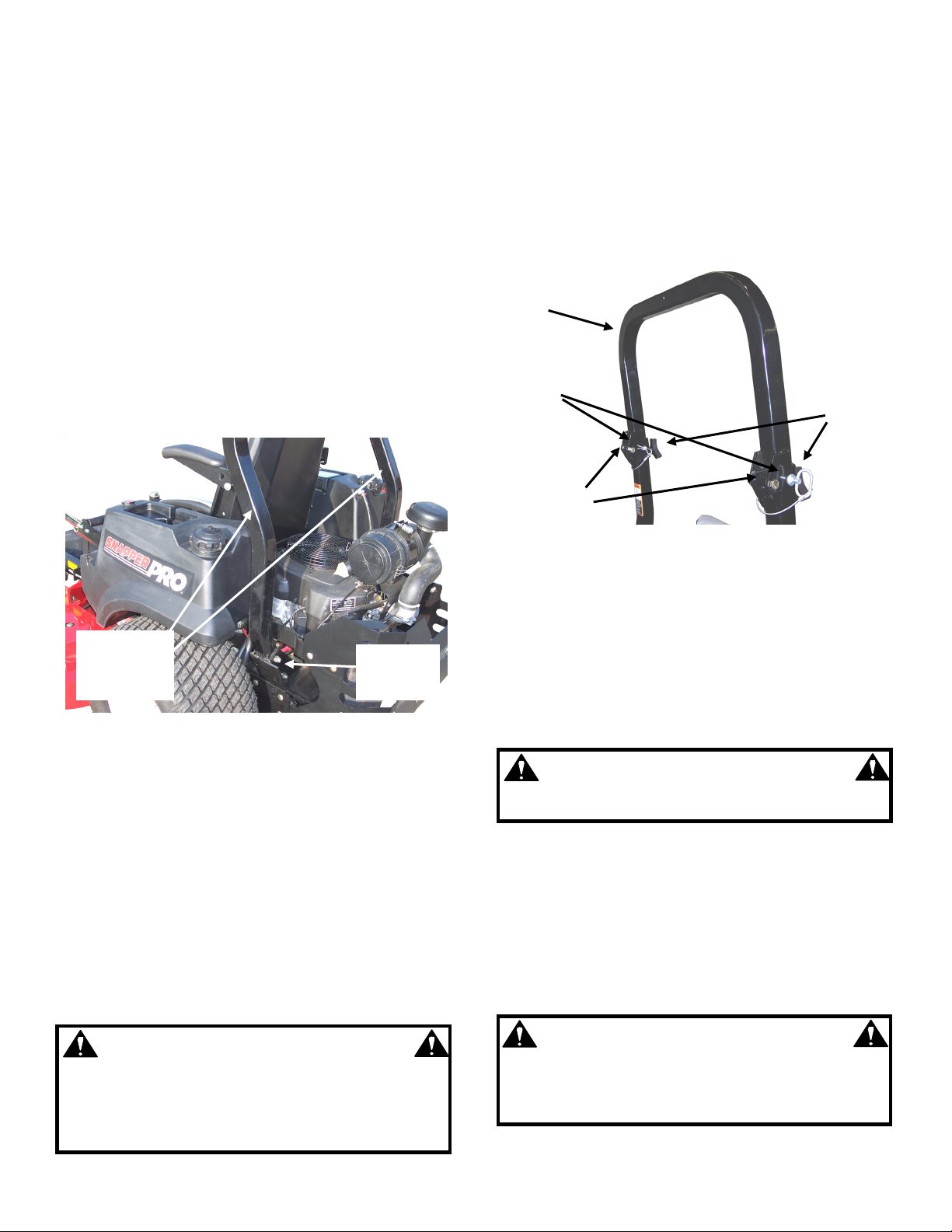
STEP 2: Install roll bar protective structure:
A. Install side bars into frame brackets behind fuel
tanks, making sure bars aim up and bend toward
front of machine. See Figure 1. Secure each bar to
its corresponding bracket with two 1/2-13 x 3-1/4”
hex bolts and lock nuts. Do not tighten yet.
SIDE BARS
UPRIGHT WITH
BENDS
FORWARD
ATTACH TO
FRAME
BRACKET
FIGURE 1
B. Attach roll bar to side bars, securing with two
1/2-13 x 3-1/4” hex bolts and lock nuts through the
hinges. See Figure 2. NOTE: Make sure roll bar tilts
backward when folded.
C. Raise roll bar to fully upright position, aligning
locking holes in roll bar with corresponding holes in
side bars. Insert locking pin through each hole, and
secure with connected bridge pin. Install star knobs
into threaded holes in front of roll bar, and tighten
securely. See Figure 2.
D. Tighten hardware securing side bars to frame
brackets, torquing to 60-70 ft-lbs. Tighten roll bar
hardware as well; however, leave loose enough so
that roll bar folds and raises easily.
WARNING
Roll bar protective structure must be installed and all
mounting hardware securely tightened before starting
or operating machine. Do Not modify the structure in
any way before, during or after installation. Modifying
the structure can result in serious injury or death.
ROLL
BAR
INSTALL
PINS
INSTALL
HARDWARE
FIGURE 2
STEP 3: Check the date on the battery label. See
Figure 3. If battery is placed into service after date
shown on label, battery will have to be charged:
A. Remove battery from the battery compartment
before charging.
B. Place battery in a well ventilated area on a level
non-concrete surface.
C. Charge the battery at 6-10 amps for 1 hour to
bring the battery to full charge.
WARNING
Keep all sparks, flame and fire away from area when
charging battery.
STEP 4: Install battery into power unit.
STEP 5: Both bolts are already installed on both
terminals. Connect positive (+) cable (red) first, from
wiring harness to the positive terminal (+) on battery
and secure with nut provided in hardware bag. Connect
negative (-) cable (black) last, to negative terminal (-)
on battery and secure with nut also provided. See
Figure 3. Apply a small amount of grease over
terminals to prevent corrosion.
WARNING
Shield the positive terminal with terminal cover
located on battery harness. This prevents metal
from touching the positive terminal, which could
cause sparks.
INSTRUCTION No. 7100083 (I.R. 8/8/2005)
1
INSTALL
STAR
KNOBS
Page 2
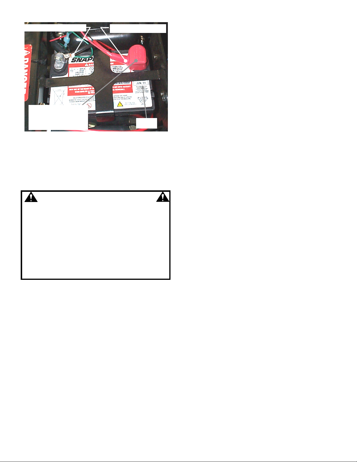
RED (POSITIVE) CABLEBLACK (NEGATIVE) CABLE
TERMINAL COVER MUST
SHIELD POSITIVE
TERMINAL AFTER
INSTALLATION
DATE
FIGURE 3
STEP 6: Take the necessary precautions, when
handling fuel. Fill the fuel tank with clean fuel. Check oil
and add oil if needed as stated in Engine Owners
Manual. Move fuel tank selector valve handle to the
desired fuel tank.
WARNING
Handle fuel with care! Use an approved fuel
container. DO NOT smoke near open fuel container
and keep fuel container away from open flame. DO
NOT fill fuel tank indoors or when engine is
running. Allow engine to cool for at least ten
minutes before refilling. Wipe off any spilled fuel
before starting engine. DO NOT run engine indoors.
Before attempting any adjustments, maintenance,
service, or repairs, stop engine and blade, always
remove key from ignition switch, remove spark plug
wire(s) and secure wire(s) away from spark plug(s).
STEP 7: MOWER DECK ADJUSTMENT (LEVELNESS)
SIDE to SIDE and FRONT to REAR
Before making deck leveling adjustments, inflate rear tires
to 12 PSI and front tires to 25 PSI. When adjusted
correctly, the deck will be level side to side within 1/8”,
have a low cut setting of approximately 1”, and the blades
pitched approximately 3/16” higher at the rear. If
adjustment is needed:
A. Place machine on a smooth level surface.
B. Check blade tips by rotating blades until tips are
pointing to the sides of the deck. Check the
measurement of outside blade tips to the ground on
both blades. The measurement of each of the outside
blade tips should be within 1/8” of each other. If
measurement of the blade tips is not within 1/8”,
adjustment should be made to the correct
measurement.
C. Move deck lift lever and set the mower deck to the
highest cutting position.
D. Relieve tension on deck lift assist spring by
loosening nut on eyebolt.
E. Place 1” blocks under the front and rear edge of the
mower deck.
F. Move deck lift lever and set the mower deck to a
lower cutting position until deck rests on the 1” blocks.
G. Loosen the nuts and bolts that secure both front
deck support chains. Adjust chains until tight and
retighten bolts and nuts. Torque to 70 ft. lbs.
H. Loosen the nuts that secure both rear deck support
eyebolts. Adjust to remove slack from both rear chains.
Tighten nuts securely.
I. Move deck lift lever and set the mower deck to the
highest cutting position and recheck side to side blade
tip dimensions. The difference between the two should
be 1/8” or less.
NOTE: The deck timing rod (rod that runs from front
deck lift arm to rear deck lift arm) is preset at the factory
and requires no adjustments.
J. The leveling blocks used in Step E should result in a
proper deck pitch. If a pitch adjustment is required, use
the two rear deck support eyebolts. Adjust up or down
as required.
K. Reinstall deck lift assist spring. Place deck in highest
cutting position. Tighten nut on eyebolt until 1 1/4” of
threads protrude past end of nut.
STEP 8: HYDRAULIC OIL RESERVOIRS
Check the level of the fluid in both of the fluid reservoirs. The
reservoirs are located underneath the operator’s seat. Wipe
away all dirt and debris from around reservoir cap before
removing. Oil must remain absolutely clean! Check with
machine on a level surface with engine “OFF”. Fill reservoir
as needed to bring level up. The reservoir is properly filled
when the fluid level is 1-1/2” below the top of the filler neck.
DO NOT OVER FILL. Use clean, fresh premium automotive
oil having a viscosity equivalent to SAE 20W50 API SL. The
fluid should be chemically stable, incorporating rust and
oxidation inhibitors. Make sure funnels, pouring spouts and oil
can are completely clean. Reinstall reservoir cap.
IMPORTANT: Re-check fluid level after operating machine for
several minutes and adjust level as needed. If one or both of
the wheel drive systems is not pulling properly, the hydraulic
system may need to be purged of entrapped air. Refer to
STEP 10, “HYDRAULIC SYSTEM, PURGING”.
STEP 9: TRACKING ADJUSTMENT – TWIN STICK
CONTROLS
Start machine. If the machine does not track straight when
the Motion Control Levers are in the maximum forward speed
position, perform the following adjustment. Rear tire pressure
must be set to 12 PSI before making this adjustment.
A. Loosen bolts that secure adjustment plates and slide
plates all the way forward. Retighten bolts.
B. Start machine and drive in smooth flat open area at
maximum forward speed.
C. If machine tracks to the right, loosen bolts that secure the
left adjustment plate. Move plate rearward to slow the left
wheel. Retighten bolts.
D. If machine tracks to the left, loosen bolts that secure the
right adjustment plate. Move plate rearward to slow the
right wheel down. Retighten bolts. See Figure 4.
E. Drive machine again. Repeat adjustment as necessary
until machine tracks straight.
2
Page 3

LOOSEN BOLTS.
SLIDE PLATE TO
MAKE MACHINE
TRACK STRAIGHT
ADJUSTMENT
PLATE
LEFT SIDE MOTION
CONTROL LEVER
FIGURE 4
STEP 10: HYDRAULIC SYSTEM, PURGING
When initially putting hydraulic system into
service, one or both of the wheel drives may not
pull properly. This is likely to be caused by air
entrapped in the system. If you experience a
pulling issue during initial setup or after completing
repairs, perform the following procedure to purge
the air from one or both of the hydraulic drive
systems.
IMPORTANT: WHEN REPLACING THE HYDRAULIC
FLUID FILTERS, PRE-FILL BOTH WITH OIL
(SAE 20W50 API SL) BEFORE INSTALLING.
PRE-FILLING THE FILTERS WITH OIL WILL
REDUCE OR POSSIBLY ELIMINATE THE NEED
TO PURGE THE SYSTEM OF ENTRAPPED AIR.
A. Locate hydraulic reservoirs underneath
operator’s seat. After thoroughly cleaning the area
around the top of each reservoir, remove filler cap.
Bring fluid to proper level (1-1/2” below the top of
the filler neck). With engine off, add SAE 20W50
automotive oil. See Figure 5.
B. Open pressure relief valve on hydraulic pump,
turning counter clockwise 2 full turns. See Figure
6.
C. Carefully raise the rear of the machine so the
wheels are off of the ground. Securely block the
machine to prevent it from falling.
D. While seated in the operator’s position, start the
engine. Place engine speed control in FAST
position.
E. Release parking brake and move motion
control levers out of the neutral lock position.
F. Slowly move motion control levers to the full
forward and then to the full reverse positions.
Repeat this process 6 times.
G. Stop engine and wait for all rotation to stop
before leaving the operator’s position.
H. Close pressure relief valve on hydraulic pump,
turning clockwise. Tighten snuggly.
I. With pressure relief valve closed, repeat Steps
D thru G.
J. Remove blocks and lower rear of machine.
K. Check fluid level in reservoirs. Add SAE 20W50
automotive oil as required to bring fluid level to 11/2” from top of filler neck. Do Not overfill.
L. Install and tighten filler cap.
HYDRAULIC
RESERVOIRS
FIGURE 5
ROTATE RELIEF VALVE
COUNTERCLOCKWISE
TO RELIEVE PRESSURE
RELIEF VALVE
FIGURE 6
3
Page 4

PRE-OPERATION CHECKLIST
Snapper has completed initial adjustments and performed operational tests prior to shipping the machine. Due to the
possible effects of shipping, handling and storage, Snapper intends for all of the following items to be verified and
necessary final adjustments made at time of setup. It remains good practice and is strongly recommended that all the items
also be checked prior to placing the machine into service. It is very important that setup is verified and all operational tests
completed and results are acceptable. After completing this form, sign and retain for future reference.
CUTTING BLADE & MOWER
___ BLADE RETAINING hardware checked for proper tightness (70-80 ft-lbs recommended).
___ MOWER CUTTING HEIGHT settings checked and adjusted as needed (with tires properly inflated).
___ MOWER SIDE TO SIDE level checked and adjusted as needed (with tires properly inflated).
___ MOWER FRONT TO REAR setting checked and adjusted as needed (with tires properly inflated).
PRE-START CHECKS & SERVICES
___ ROLL BAR PROTECTIVE STRUCTURE installed, and hardware tightened to 60-70 ft-lbs (side bar hardware only;
roll bar hardware should allow roll bar to be folded and raised easily).
___ TIRES checked and inflated to correct pressures.
___ ENGINE OIL level checked. See Engine Owners Manual.
___ FUEL added to tank and system checked for leaks.
___ BATTERY charged (if needed) and properly connected, with red boot over positive terminal.
___ HYDRAULIC FLUID level checked.
OPERATIONAL TESTS
___ CHECK SEAT SWITCH for proper function.
___ INTERLOCK SYSTEMS checked to insure proper functioning.
___ SEAT BELTS checked for proper operation.
___ ENGINE STARTED and throttle control settings checked.
___ ALL OPERATIONS as listed on console checked.
___ IGNITION SWITCH checked to insure engine stops when turned to OFF position.
___ PARKING BRAKE tested to insure proper operation.
___ BLADE ENGAGEMENT SWITCH tested for engagement and disengagement of blade.
___ BLADE BRAKE function verified. Blade rotation stops in 7 seconds or less.
___ MACHINE TRACKING tested and adjusted as required.
DEMONSTRATION & INSTRUCTION
___ DEMONSTRATED proper operation of mower to purchaser.
___ INSTRUCTED purchaser to read and follow instructions in Operator's Manual.
___ PERSONALLY HANDED Operator's Manual to purchaser.
___ ASSISTED purchaser in completing Product Registration cards.
DEALER'S RECORDS
Sale Date
Dealer's Name
Address _____________________________ City
Will Mower be used Commercially? Yes ___________________ No
Purchaser's Name
Address __________________________________ City
IMPORTANT: This form is to be retained by the dealer for future reference regarding Warranty, proof of purchase,
traceability for product recall or service, etc. Complete the Product Registration Card and Mail to Customer Service
Department at SNAPPER, PO BOX 1379, McDonough, Georgia, 30253.
COPYRIGHT © 2005
SNAPPER – A DIVISION OF SIMPLICITY MFG., INC.
ALL RIGHTS RESERVED
Model Serial No.
Signature
State Zip
Signature
State Zip
INSTRUCTION No. 7100083 (I.R. 8/8/2005)
4
 Loading...