

Page 1
Mid Frame Snowthrower
Not for
Reproduction
Mfg. No. Description
1695678 Dual Stage Snowthrower, 13.5 TP, 24 Inch
1738329
Revision A
Page 2

Thank you for purchasing this quality-built Snapper snow thrower. We’re pleased that you’ve placed your confidence in the Snapper
Not for
Reproduction
brand. When operated and maintained according to the instructions in this manual, your Snapper product will provide many years of dependable service.
This manual contains safety information to make you aware of the hazards and risks associated with snow throwers and how to avoid
them. This snow thrower is designed and intended only for snow throwing and is not intended for any other purpose. It is important that
you read and understand these instructions throroughly before attempting to start or operate this equipment. This snow thrower
requires final assembly before use. Refer to the Quck Start Guide for instructions on final assembly procedures. Follow the instructions
completely. Save these instructions for future reference.
Product Identification Tag
Product Identification Tag
Model / Modéle / Model xxxxxxxx
Serial / Sèrie / Serie xxxxxxxxxx
Briggs & Stratton Power Products Group, L.L.C.
Milwaukee, WI 53201 USA
When contacting your authorized dealer for replacement
parts, service, or information you MUST have these numbers.
Record your model name/number, manufacturer’s identification
numbers, and engine serial numbers in the space provided for
easy access. These numbers can be found in the locations
shown.
The Illustrated Parts List for this machine can be downloaded from www.snapper.com. Please provide model and serial number when
ordering replacement parts.
Model Description Name/Number
Unit MFG
Mower Deck MFG Number
Dealer Name
Engine Make
Engine Type/Spec
PRODUCT REFERENCE DATA
Number
ENGINE REFERENCE DATA
Unit SERIAL Number
Mower Deck SERIAL
Date Purchased
Engine Model
Engine Code/Serial Number
Number
Snapper Products
535 Macon St.
McDonough, GA 30253
1-800-317-7833
snapper.com
2
Page 3

TABLE OF CONTENTS
Not for
Reproduction
OPERATOR SAFETY.................................................................................... 4
FEATURES AND CONTROLS .......................................................................... 10
OPERATION ............................................................................................. 12
BEFORE OPERATING SNOW THROWER................................................................................. 12
OPERATE THE SNOW THROWER.............................................................................................................. 12
STOP THE SNOW THROWER.................................................................................................................... 13
TRACTION LOCK PINS ............................................................................................................................. 13
DISCHARGE CHUTE AND DEFLECTOR .................................................................................................... 14
CHECK THE OIL (BEFORE STARTING ENGINE) ........................................................................................ 15
FILL THE FUEL TANK................................................................................................................................ 15
START THE ENGINE .................................................................................................................................. 16
STOP THE ENGINE.................................................................................................................................... 17
CLEAR A CLOGGED DISCHARGE CHUTE.................................................................................................18
OPERATING TIPS...................................................................................................................................... 18
MAINTENANCE ......................................................................................... 20
SERVICE RECOMMENDATIONS ............................................................................................................... 20
LUBRICATE AUGER GEAR BOX................................................................................................................. 20
LUBRICATE AUGER SHAFT FITTINGS ...................................................................................................... 20
CHECK/LUBRICATE FREE-HAND LINKAGE.............................................................................................. 20
LUBRICATE CHUTE ROTATION GEAR ....................................................................................................... 20
ADUST THE DRAG ON THE CHUTE ROTATION......................................................................................... 20
ENGINE MAINTENANCE ........................................................................................................................... 20
CHANGE THE SPARK PLUG...................................................................................................................... 22
ADJUST SKID HEIGHT.............................................................................................................................. 23
BELT ADJUSTMENT.................................................................................................................................. 23
BELT GUIDE ADJUSTMENT ...................................................................................................................... 24
SPEED CONTROL ROD ADJUSTMENT ..................................................................................................... 25
CHECK AND ADJUST THE CABLES.......................................................................................................... 25
AUGER CONTROL CABLE ADJUSTMENT................................................................................................. 25
TRACTION CONTROL CABLE ADJUSTMENT ........................................................................................... 26
AUGER SHEAR PIN REPLACEMENT ......................................................................................................... 27
CHECK THE TIRES.................................................................................................................................... 27
STORAGE................................................................................................ 28
OFF SEASON STORAGE............................................................................................................................ 28
LUBRICATE HEX SHAFT AND CHAINS..................................................................................................... 28
REMOVE FROM STORAGE........................................................................................................................ 28
TROUBLESHOOTING................................................................................... 29
WARRANTIES........................................................................................... 31
SPECIFICATIONS ....................................................................................... 33
3
Page 4
product
OPERATOR SAFETY
Not for
Reproduction
DANGER - Amputation Hazard
The discharge chute contains a rotating
impeller to throw snow. Never clear or unclog
the discharge chute with your hands. Fingers
can quickly become caught and traumatic
amputation or severe laceration will result.
Always use a clean-out tool to clear or unclog
the discharge chute.
DANGER
• Hand contact with the rotating impeller inside the discharge
chute is the most common cause of injury associated with
snow throwers.
• This snow thrower is capable of amputating hands and feet,
and throwing objects. Read and observe all the safety
instructions in this manual. Failure to do so will result in
death or serious injury.
Safety Alert Symbol and Signal Words
The safety alert symbol and signal word (DANGER,
WARNING, CAUTION, or NOTICE) is used to indicate the likelihood and potential severity of personal injury and/or damage to
the product. In addition, a hazard symbol may be used to
represent the type of hazard.
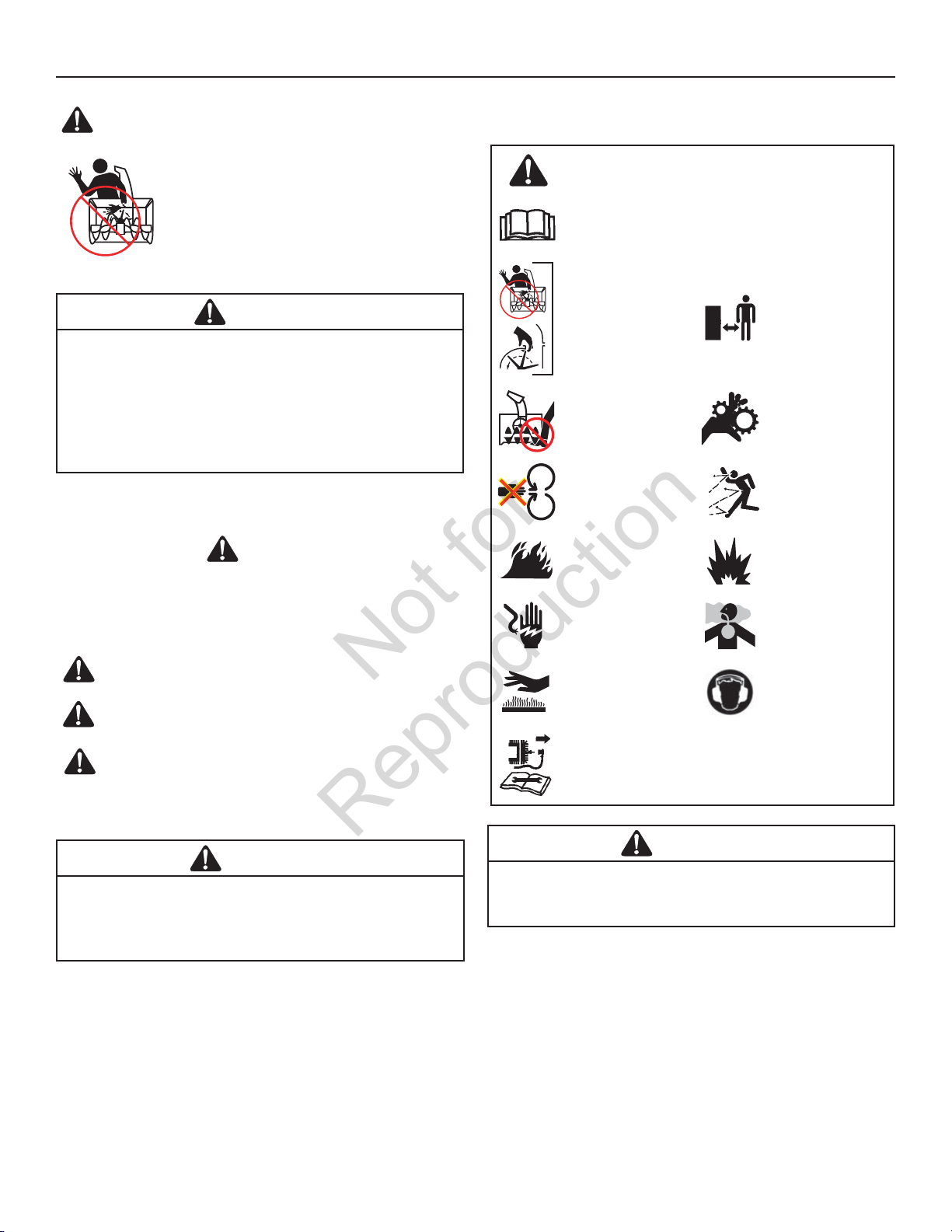
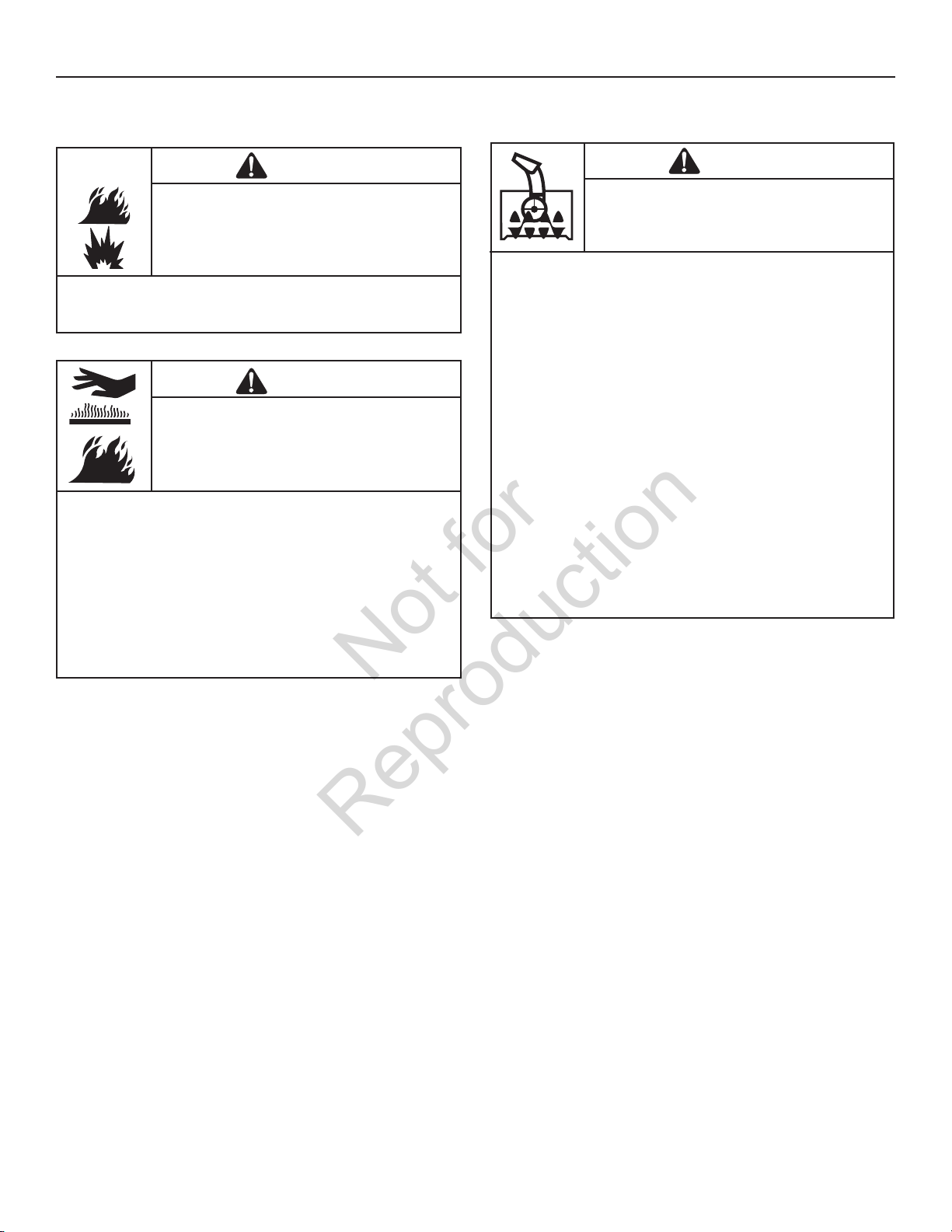
Hazard Symbols and Meanings
Safety Alert – Identifies safety information about
hazards that can result in personal injury.
Operator’s Manual – Read and understand before
performing any activity or running snow thrower.
Rotating Impeller
Rotating Auger Rotating Gears
Never Reach into
Rotating Parts
Fire Explosion
Shock Toxic Fumes
Keep a Safe
Distance from
Snow Thrower
Thrown Objects
DANGER indicates a hazard which, if not avoided, will
result in death or serious injury.
WARNING indicates a hazard which, if not avoided, could
result in death or serious injury.
CAUTION indicates a hazard which, if not avoided, could
result in minor or moderate injury.
NOTICE indicates a situation that could result in damage
to the
.
WARNING
U.S.A. Models: Certain components in this product and its
related accessories contain chemicals known to the state of
California to cause cancer, birth defects, or other reproductive
harm. Wash hands after handling.
Recommended
Hot Surface
Shut off engine and remove spark plug connector
before performing maintenance or repair work.
Ear Protection for
Extended Use
WARNING
U.S.A. Models: The engine exhaust from this product contains chemicals known to the State of California to cause
cancer, birth defects, or other reproductive harm.
4
Page 5
1
2
Free-Hand
TM
Control
Easy-Turn
TM
Traction Control
Read, understand, and follow all the instructions on the
snow thrower and in the operator’s manual before operating
this unit.
Failure to observe the safet y instructions in this manual will
result in death or serious injury.
DANGER: Hand contact with the rotating impeller inside the discharge
chute is the most common cause of injury associated with snow
throwers. Never use your hands to clean out the discharge chute.
Discharge chute contains rotating impeller to throw snow.
Never clear or unclog the discharge chute with your hands.
Fingers can quickly become caught in the impeller. Always
use a clean-out tool.
Failure to observe these safety instructions will result in
traumatic amputation or severe laceration.
OPERATOR SAFETY
Not for
Reproduction
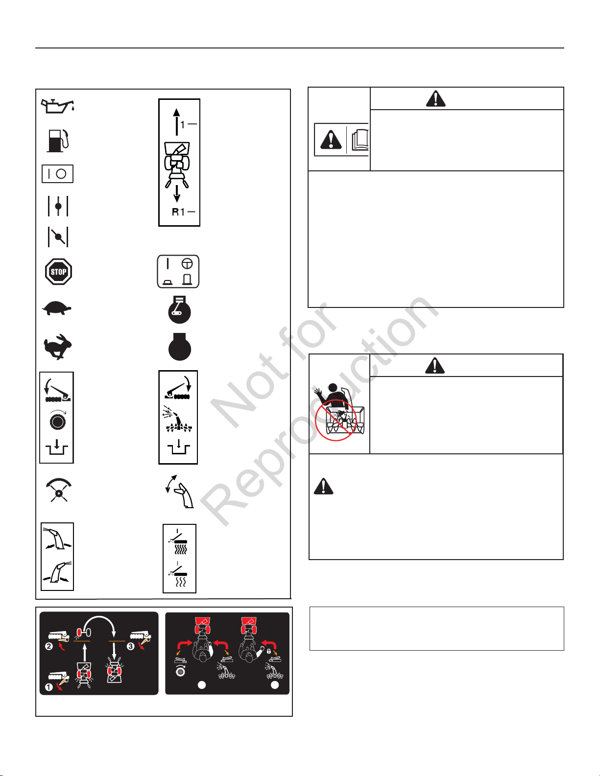
Control Symbols on Equipment
Oil
Fuel Forward
On Off Neutral
Choke Off Reverse
Choke On
Stop
Slow Engine - Run
Fast
STOP
Electric Start Engage (Down) &
Disengage (Up)
Engine - Stop
Read the Manual
DANGER
• Be thoroughly familiar with the controls and the proper use of the snow
thrower.
• Make sure you are properly trained before operating the snow thrower.
• Know how to stop the unit and disengage the controls quickly.
• Never allow anyone to operate the snow thrower without proper instruction.
• Always follow the instructions in the operator’s manual, if the snow thrower
will be stored for an extende d period.
• Maintain or replace safety and instruction labels as necessary.
• Never attempt to make major repairs on the snow thrower unless you have
been properly trained. Improper servicing of the snow thrower can result
in hazardous operation, equipment damage, and voiding of the product
warranty.
Discharge Chute
Traction Control Engage (Down)
Auger Clutch
Discharge Chute
(Left and Right)
Auger Control Engage (Down)
Chute Deflector
(Up and Down)
Heated Hand Grips
(High and Low)
DANGER
TO SAFELY CLEAR A CLOGGED DISCHARGE CHUTE
FOLLOW THESE INSTRUCTIONS:
1. Shut OFF the engine.
2. Wait 10 seconds to be sure the impeller blades have stopped rotating.
3. Always use a clean-out tool, not your hands.
NOTE: Not all control symbols shown on this page will appear
on your snow thrower. See FEATURES AND CONTROLS section
for the applicable symbols.
F
5
Page 6

Fuel and its vapors are extremely flammable and explosive.
Always handle fuel with extreme care.
Failure to observe these safety instructions can cause a fire
or explosion which will result in severe burns or death.
This snow thrower is only as safe as the operator. If it is
misused, or not properly maintained, it can be dangerous.
Remember you are responsible for your safety and that of
those around you.
OPERATOR SAFETY
Not for
Reproduction
Operation and Equipment Safety
DANGER
• Keep the area of operation clear of all persons, particularly small children
and pets.
• Thoroughly inspect the area where the snow thrower will be used and remove
all doormats, sleds, boards, wires, and other foreign objects.
• Do not operate the snow thrower without wearing adequate winter clothing.
• Wear footwear that will improve footing on slippery surfaces.
• Use caution to avoid slipping or falling especially when operating the
snow thrower in reverse.
• Never operate the snow thrower without good visibility or light. Always be
sure of your footing, and keep a firm hold on the handles.
• Do not clear snow across the face of slopes. Use extreme caution when
changing direction on slopes. Do not attempt to clear steep slopes.
• Do not overload the machine capacity by attempting to clear snow too
quickly.
• Never operate the snow thrower at high transport speeds on slippery
surfaces. Look behind the snow thrower and use care when operating in
reverse.
• Do not use the snow thrower on surfaces above ground level such as roofs of
residences, garages, porches, or other such structures or buildings.
• Operators should evaluate their ability to operate the snow thrower safely
enough to protect themselves and others from injury.
• The snow thrower is intended to remove snow only. Do not use the snow
thrower for any other purpose.
• Do not carry passengers.
• After striking a foreign object, shut OFF the engine, disconnect the cord on
electric motors, thoroughly inspect the snow thrower for any damage, and
repair the damage before restarting and operating the snow thrower.
• If the snow thrower vibrates abnormally, shut OFF the engine. Vibration is
generally a warning of trouble. See an authorized dealer if necessary for
repairs.
• For models equipped with electric starting motors, disconnect the power
cord after the engine starts.
Fuel Handling
DANGER
WHEN ADDING FUEL
• Turn off engine and let cool at least 2 minutes before removing the fuel
cap and adding fuel.
• Fill fuel tank outdoors or in a well ventilated area.
• Do not overfill the fuel tank. To allow for the expansion of gasoline, do not fill
above the bottom of the fuel tank neck.
• Keep fuel away from sparks, open flames, pilot lights, heat, and other
ignition sources.
• Check fuel lines, cap, and fittings frequently for cracks or leaks. Replace if
necessary.
• Use an approved fuel container.
• If fuel spills, wait until it evaporates before starting engine.
WHEN STARTING ENGINE
• Ensure that spark plug, muffler, fuel cap, and air cleaner (if equipped) are in
place and secured.
• Do not crank the engine with the spark plug removed.
• If fuel is spilled, do not attempt to start the engine, but move the snow
thrower away from the area of the spill, and avoid creating any source of
ignition, until the fuel vapors have dissipated.
• Do not over-prime the engine. Follow the engine starting instructions in this
manual.
• If the engine floods, set choke (if equipped) to OPEN/RUN position, move
throttle (if equipped) to FAST position and crank until engine starts.
WHEN OPERATING EQUIPMENT
• Do not tip the snow thrower at an angle which causes the fuel to spill.
• Do not choke the carburetor to stop the engine.
• Never run the engine with the air cleaner assembly (if equipped) or the air
filter (if equipped) removed.
WHEN CHANGING OIL
• If you drain the oil from the top oil fill tube, the fuel tank must be empty or
fuel can leak out and result in a fire or explosion.
WHEN TRANSPORTING EQUIPMENT
• Transport with fuel tank EMPTY, or with fuel shut-off valve OFF.
WHEN STORING GASOLINE OR EQUIPMENT WITH FUEL IN TANK
• Store away from furnaces, stoves, water heaters, or other appliances that have
pilot light or other ignition source because they can ignite fuel vapors.
6
Page 7
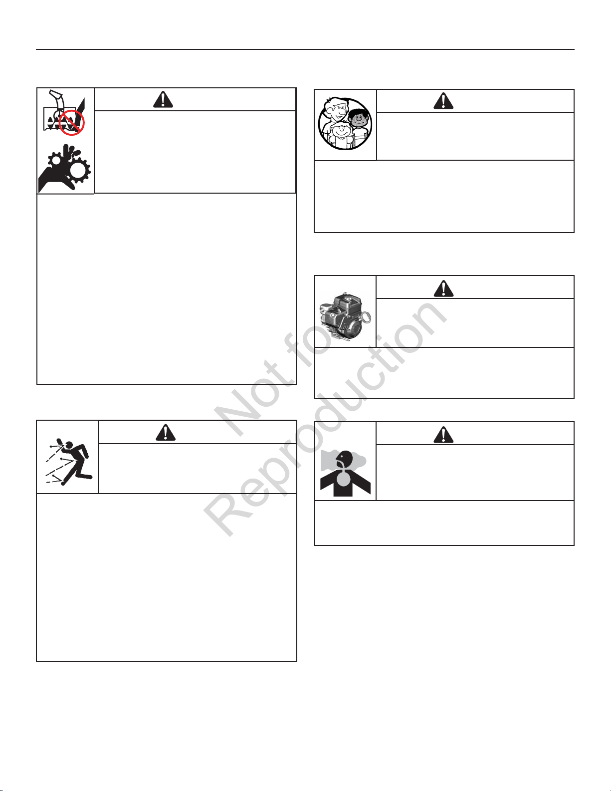
Tragic accidents can occur if the operator is not alert to the
presence of children. Children are often attracted to the unit
and the operating activity. Never assume that children will
remain where you last saw them.
Engines give off carbon monoxide, an odorless, colorless,
poison gas.
Breathing carbon monoxide can cause nausea, fainting,
or death.
Safe operation of the snow thrower requires the proper care
and maintenance of the engine. Failure to observe the safety
instructions in this manual will result in death or serious
injury.
Objects can be picked up by auger and thrown from chute.
Never discharge snow toward bystanders or allow anyone in
front of the snow thrower. Failure to observe these safety
instructions will result in death or serious injury.
Keep hands, feet, and clothing away from rotating parts.
Rotating parts can contact or entangle hands, feet, hair,
clothing, or accessories.
Failure to observe these safety instructions will result in
traumatic amputation or severe laceration.
OPERATOR SAFETY
Not for
Reproduction
Moving Parts
DANGER
• Whenever cleaning, repairing, or inspecting the snow thrower, make sure the
engine is OFF, spark plug wire is disconnected, and all moving parts have
stopped.
• Do not put hands or feet near or under rotating parts. Keep clear of the
discharge opening at all times.
• Never operate the snow thrower without proper guards, and other safety
devices in place and working.
• Never leave the snow thrower unattended while engine is running. Always
disengage the auger and traction controls, stop engine, and remove keys.
• Keep all loose clothing away from the front of the snow thrower and auger.
Scarves, mittens, dangling drawstrings, loose clothes, and pants can quickly
become caught in the rotating device and amputation will occur. Tie up
long hair and remove jewelry.
• Run the machine a few minutes after discharging snow to prevent freeze-up
of the collector/impeller.
• Disengage power to the collector/impeller when snow thrower is transported
or not in use.
Thrown Objects
Children
DANGER
• Keep children out of the area during operation. Children are often attracted to
the equipment. Be mindful of all persons present.
• Be alert and turn unit off if children enter the area.
• Never allow children to operate the unit.
• Use extra care when approaching blind corners, shrubs, trees, or other
objects that may obscure vision. Children may be present.
Engine Safety
DANGER
• Disengage all clutches and shift into neutral before starting the engine.
• Let the engine adjust to outdoor temperatures before starting to clear snow.
• Use a grounded three-wire plug-in for all snow throwers equipped with
electric drive motors or electric starting motors.
DANGER
• Always wear safety glasses or eye shields while during operation, and while
performing an adjustment or repair.
• Always be aware of the direction the snow is being thrown. Nearby
pedestrians, pets, or property may be harmed by objects being thrown.
• Be aware of your environment while operating the snow thrower. Running
over items such as, gravel, doormats, newspapers, toys, and rocks hidden
under snow, can all be thrown from the chute or jam in the auger.
• Use extreme caution when operating on or crossing gravel drives, walks, or
roads.
• Adjust the collector housing height to clear gravel or crushed rock surface.
• Never operate the snow thrower near glass enclosures, automobiles, window
wells, drop-offs, and the like without proper adjustment of the discharge
chute angle.
• Familiarize yourself with the area in which you plan to operate the snow
thrower. Mark off boundaries of walkways and driveways.
DANGER
• Start and run engine outdoors.
• Do not run the engine in an enclosed area, even if doors or windows are
open.
7
Page 8
This snow thrower must be properly maintained to ensure safe
operation and performance. Failure to observe the safety
instructions in this manual could result in death or serious
injury.
Starting engine creates sparking.
Sparking can ignite nearby flammable gases.
Explosion and fire could result.
U.S.A. Models:
Running the engine produces heat. Engine parts, especially
muffler, become extremely hot.
Failure to observe these safety instructions could result in
severe thermal burns on contact.
OPERATOR SAFETY
Not for
Reproduction
Engine Safety (Continued)
WARNING
-
• If there is natural or LP gas leakage in area, do not start engine.
• Do not use pressurized starting fluids because vapors are flammable.
WARNING
• Never touch a hot engine or muffler. Allow muffler, engine cylinder, and fins
to cool before touching.
• Remove debris from muffler area and cylinder area.
• Install and maintain in working order a spark arrester before using equipment
on forest-covered, grass-covered, or brush-covered unimproved land.
•U
Section 4442 to use or operate the engine on or near any forest-covered,
brush-covered, or grass-covered land unless the exhaust system is equipped
with a spark arrester meeting any applicable local or state laws. Other states
or federal areas may have similar laws.
It is a violation of California Public Resource Code
Maintenance and Storage
WARNING
• When performing any maintenance or repairs on the snow thrower, shut OFF
the engine, disconnect spark plug wire, and keep the wire away from the
plug to prevent someone from accidently starting the engine.
• Check shear bolts and other hardware at frequent intervals for proper
tightness to be sure the snow thrower is in safe working condition.
• Keep nuts and bolts tight and keep snow thrower in good condition.
• Never tamper with safety devices. Check their proper operation regularly and
make necessary repairs if they are not functioning properly.
• Components are subject to wear, damage, and deterioration. Frequently
check components and replace with recommended parts, when necessary.
• Check control operation frequently. Adjust and service as required.
• Use only factory authorized replacement parts when making repairs.
• Always comply with factory specifications on all settings and adjustments.
• Only authorized service locations should be utilized for major service and
repair requirements.
• Use only attachments and accessories approved by the factory (such as
wheel weights, counterweights, or cabs).
• Never attempt to make any adjustments while the engine is running (except
when specifically recommended by the factory).
8
Page 9
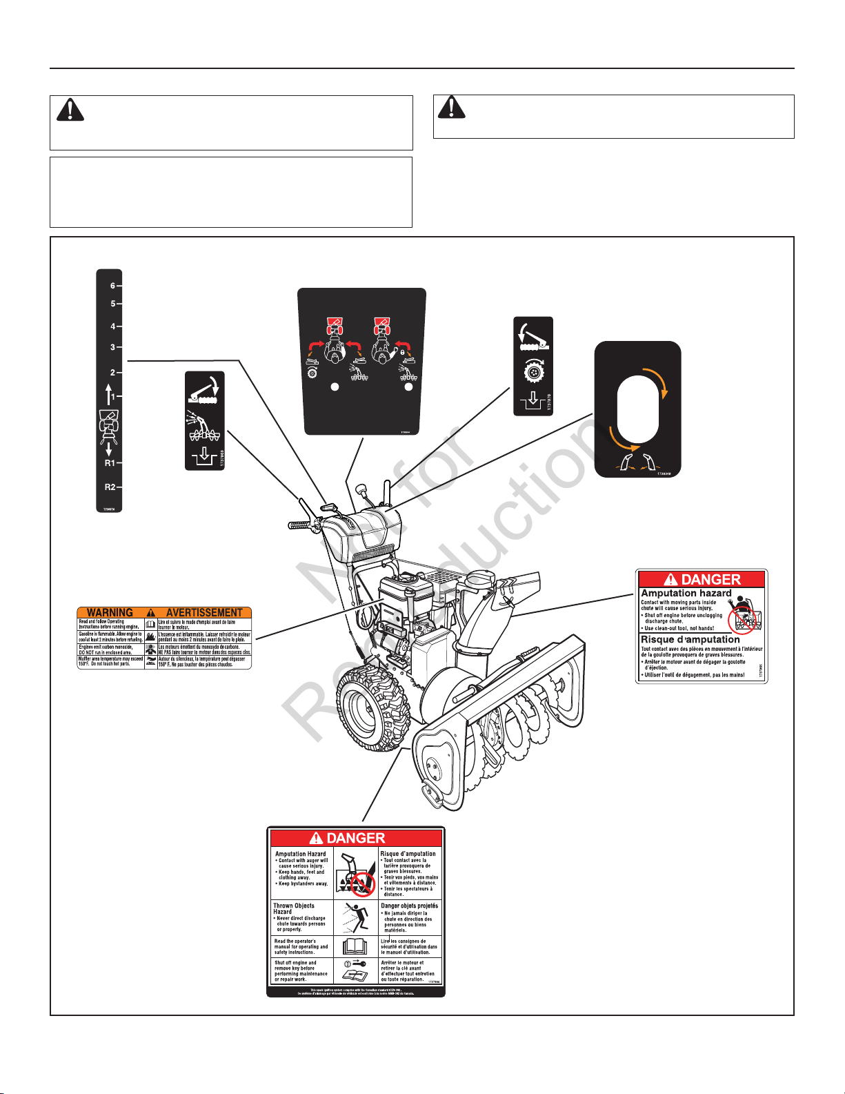
If any safety decals become worn or damaged and
cannot be read, order replacement decals from your local dealer.
OPERATOR SAFETY
Not for
Reproduction
Look for this symbol to indicate important safety
pre cautions. This symbol indicates: “Attention! Become
Alert! Your Safety Is At Risk.”
Before operating your snow thrower, read the safety decals
as shown on your snow thrower. The cautions and warnings
are for your safety. To avoid a personal injury or damage to
your snow thrower, understand and follow all the safety decals.
Part No. 1738344
Free-Hand
Part No. 1736616
Shift Decal
Part No. 1737869
Auger Control Decal
TM
Control Decal
1
WARNING:
Traction Control Decal
2
Part No. 1737870
Part No. 1738348
Chute Rotation Crank Decal
Part No. 278297
Engine Decal
Part No. 1737866
Auger Danger Decal
Part No. 1737865
Chute Danger Decal
Safety Decals Figure 1
9
Page 10
FEATURES AND CONTROLS
Not for
Reproduction
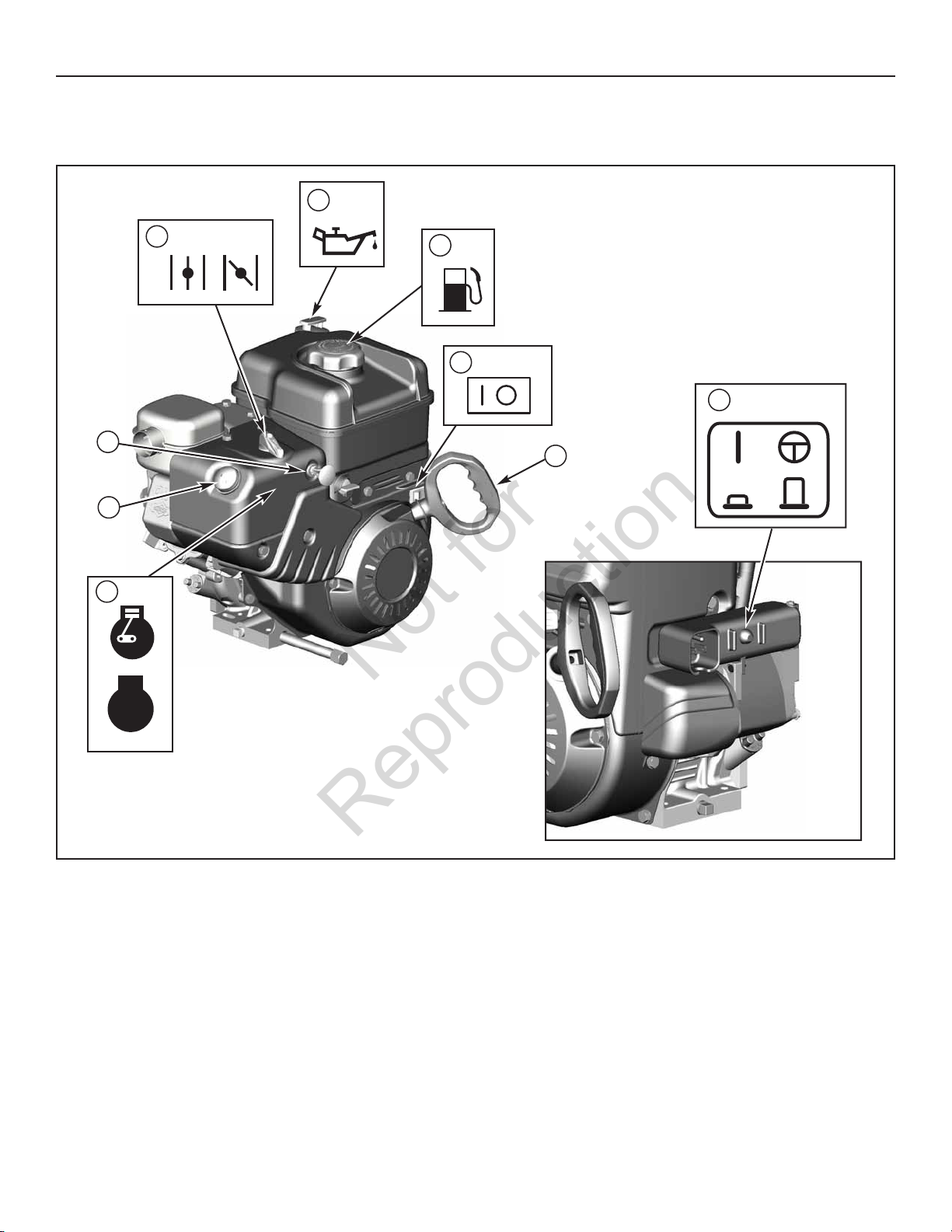
NOTICE: Read this OPERATOR’S MANUAL and OPERATOR SAFETY before operating your snow thrower. Compare the illustrations with your
SNOW THROWER to familiarize yourself with the location of various controls and adjustments. Save this manual for future reference.
H
A
D
C
I
G
F
B
E
STOP
Engine Controls Figure 2
ENGINE AND SNOW THROWER CONTROLS
ENGINE CONTROLS
A. Choke Control Knob — Used to start a cold engine (see Figure 2).
B. Electric Start Button — Used to start the engine using the electric
starter.
C. Primer Button — Used to inject fuel directly into the carburetor
manifold to ensure fast starts in cool weather.
D. Safety Key — Must be inserted to start engine. Pull out to stop. Do
not turn safety key.
E. Starter Cord Handle — Used to start the engine manually.
F. ON/OFF Switch — Used to start and stop the engine.
G. Fuel Tank and Cap — Fill the fuel tank to approximately 1-1/2 in.
(38 mm) below the top of the neck to allow for fuel expansion.
H. Oil Fill Cap (Extended Dipstick)
SNOW THROWER CONTROLS
A. Speed Select Lever — Allows the operator to use one of six (6)
forward and two (2) reverse speeds (see Figure 3). To shift, move
speed select lever to desired position.
NOTICE: Do not move speed select lever while Traction
Drive Clutch is engaged. This may result in severe damage
to drive system.
10
Page 11
FEATURES AND CONTROLS
1
2
Not for
Reproduction
A
C
B
F
E
D
H
G
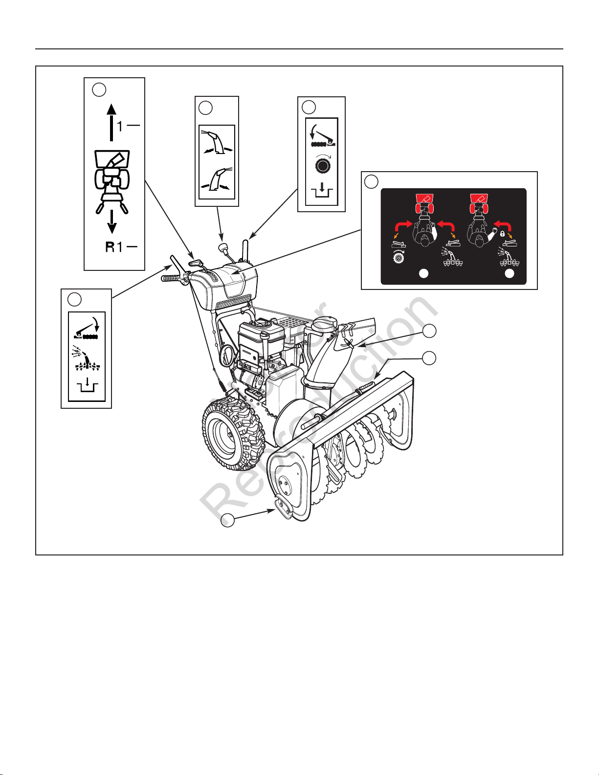
Snow Thrower Controls Figure 3
B. Auger Control Lever — Used to engage and disengage the
auger and impeller. To engage push down, to disengage release.
C. Chute Rotation Crank — Used to rotate the discharge chute to the
left or right.
D. Chute Deflector Knob — Used to control the angle of the chute
deflector (up or down).
TM
E. Free-Hand
hand) and auger control (right hand), allows the operator to
release the auger control lever to use the other controls.
Control — After engaging the traction control (left
F. Traction Drive Clutch Lever — Used to propel snow thrower for-
ward or reverse. Push down to engage, release to disengage.
G. Skid Shoe — Used to adjust ground clearance of auger housing.
H. Clean-Out Tool — Used to remove snow and debris from the dis-
charge chute and the auger housing.
11
Page 12

1
2
Free-Hand
TM
Control
OPERATION
■ Check the fasteners. Make sure all fasteners are tight.
■ On electric start models, the unit was shipped with the starter cord
plugged into the engine. Before operating, unplug the starter cord from the
engine.
C
C
A
Not for
Reproduction
BEFORE OPERATING SNOW THROWER
■
■
WARNING: The operation of any snow thrower can result in foreign objects being thrown into the eyes, which can result in
severe eye damage. Always wear safety glasses or eye shields before beginning snow thrower operation. We recommend
standard safety glasses or Wide Vision Safety Mask over spectacles.
OPERATE THE SNOW THROWER
CAUTION: Operation with a Snow Cab. Wind may blow
exhaust gasses back towards the operator. If you notice
the smell of exhaust, change direction of operation.
NOTICE: Do not throw snow toward a building as hidden objects
could be thrown with sufficient force to cause damage.
1. Start the engine. See “To Start Engine” in this section.
2. Turn the chute rotation crank (A
right) of the discharge chute. See “Discharge Chute and Deflector” in
this section.
3. Loosen the wing nut on the side of the discharge chute to set angle
(up or down) the snow is thrown. See “Discharge Chute and Deflector”
in this section.
, Figure 4) to set the direction (left or
NOTE: This snow thrower was shipped WITH OIL in the
engine. See “Before Starting Engine” instructions in the
OPERATION section of this manual before starting engine.
CAUTION: Before operating, make sure the area in
front of the snow thrower is clear of bystanders or
obstacles.
4. Fully press and hold the auger control lever (BBto engage auger
rotation. Releasing the auger control lever will disengage the auger unless the Free-Hand™ control has been activated.
5. Fully press and hold the traction and Free-Hand™ control lever (C
engage the traction drive and begin moving the snow thrower. To disengage the traction drive, completely release the lever.
6. When BOTH levers are depressed, the Free-Hand™ control is activated. This allows auger control lever to be released - YET AUGER
ROTATION WILL CONTINUE - until the Free-Hand™ control is released.
) to
A
C
D
B
Control Levers Figure 4
NOTE: Always release the traction control lever before moving
the speed select lever.
7. Use the speed select lever (DD) to select the forward drive speed. Set
the speed select lever to one of the following positions as determined
by snow conditions:
1-2 Wet, Heavy, Slushy, Extra Deep
3 Moderate
4-5 Very Light
6 Transport
NOTE: When clearing wet, heavy, snow, it is recommended
that the ground speed of the unit be reduced, maintained full
throttle and do not attempt to clear the full width of the unit.
8. To stop moving forward, release the traction control lever (C
9. To move the snow thrower backwards, move the speed select lever into
either first or second reverse position and engage the traction control
lever.
).
12
Page 13

OPERATION
C
A
A
Not for
Reproduction
STOP THE SNOW THROWER
1. Release the auger control lever (BB,Figure 4).
2. Release the traction control lever (C
3. Push the ON/OFF switch (A
out the safety key (BB).
WARNING: Never run engine indoors or in an enclosed,
poor ventilated area. Engine exhaust contains CARBON
MONOXIDE, an ODORLESS and DEADLY GAS.
• Keep hands, feet, hair, and loose clothing away
from any moving parts on engine and snow
thrower.
• Temperature of muffler and nearby areas can
exceed 150°F (66°C). Avoid these areas.
• DO NOT allow children or young teenagers to
operate or be near snow thrower while it is
operating.
).
, Figure 13) to the OFF position and pull
TRACTION LOCK PINS
The right traction wheel can be completely released using the locking pin
(A
, Figure 5). This allows the unit to be easily moved with the engine off.
WARNING: Read Operator’s Manual before operating
machine. This machine can be dangerous if used
carelessly.
• Never operate the snow thrower without all guards,
covers, shields in place.
• Never direct discharge towards windows or allow
bystanders near machine while engine is
running.
• Stop the engine whenever leaving the operating
position.
• Disconnect spark plug before unclogging the
impeller housing or the discharge chute and
before making repairs or adjustments.
• When leaving the machine, remove the safety key.
To reduce the risk of fire, keep the machine clean
and free from spilled gas, oil, and debris.
A
Traction Lock Pins Figure 5
13
Page 14

B
OPERATION
Not for
Reproduction
DISCHARGE CHUTE AND DEFLECTOR
Discharge Chute Rotation (Left/Right)
1. Turn the chute rotation crank (AA, Figure 6) clockwise to turn chute to
the right. Turn crank counterclockwise to turn chute to the left.
2. After the desired position is obtained, release the crank.
Chute Deflector (Up/ Down)
1. Loosen the wing nut (AA, Figure 6) on the side of the discharge
chute (B
).
2. Raise the deflector to provide a higher stream and greater distance. Or,
lower the deflector to provide a lower stream and less distance.
3. After the desired angle is obatained, tighten the wing nut.
A
A
B
Setting the Chute Deflector Angle Figure 7
Setting the Discharge Chute Rotation Figure 6
14
Page 15

DO NOT
CHECK THE OIL (BEFORE STARTING ENGINE)
A
FULL
Not for
Reproduction
NOTE: The engine was shipped from the factory filled with oil.
Check the level of the oil. Add oil as needed.
1. Make sure the unit is level. Use a high quality detergent oil classified
“For Service SG, SH, SJ, SL, or higher”.
2. Remove the oil fill cap/dipstick (A
3. Insert the oil fill cap/dipstick and turn clockwise to tighten.
4. Remove the oil fill cap/dipstick and check the oil.
NOTE: Do not check the level of the oil while the engine runs.
5. If necessary, add oil until the oil reaches the FULL mark on the oil fill
cap/dipstick. Do not add too much oil.
6. Tighten the oil fill cap/dipstick securely each time you check the oil
level.
NOTE: Synthetic 5W30 motor oil is acceptable for all temperatures. DO NOT mix oil with gasoline. See Chart for oil recommendations.
, Figure 8) and wipe with a clean cloth.
OPERATION
* Below 40°F (4°C) the use of SAE 30 will result in hard starting.
** Above 80°F (27°C) the use of 10W-30 may cause increased oil consumption. Check
oil level more frequently.
FULL
FILL THE FUEL TANK
This engine is certified to operate on gasoline. Exhaust Emission Control
System: EM (Engine Modifications).
Fill the fuel tank with fresh, clean, unleaded regular, unleaded premium, or reformulated automotive gasoline with a minimum of 85 octane along with a
fuel stabilizer (follow instructions on fuel stabilizer package). D
leaded gasoline. We recommend that fuel stabilizer be added to the fuel
each time that gasoline is added to the fuel tank.
NOTE: Winter grade gasoline has higher volatility to improve
starting. Be certain container is clean and free from rust or
other foreign particles. Never use gasoline that may be stale
from long periods of storage in the container.
CAUTION: DO NOT use gasoline containing any
amount of alcohol as it can cause serious damage to
the engine or significantly reduce the performance.
use
A
Checking the Oil
WARNING: Gasoline is flammable. Always use
caution when handling or storing gasoline. Turn
engine off and let engine cool at least two minutes before
removing the gas cap. Do not add gasoline to the fuel tank
while snow thrower is running, hot, or when snow thrower
is in an enclosed area. Keep away from open flame,
electrical sparks and DO NOT SMOKE while filling the fuel
tank. Never fill the fuel tank completely; but fill the fuel
tank to within 1-1/2 inches (3.8 mm) from the top to
provide space for the expansion of the fuel. Always fill fuel
tank outdoors and use a funnel or spout to prevent spilling.
Make sure to wipe up any spilled fuel before starting the
engine.
Store gasoline in a clean, approved container, and keep
the cap in place on the container. Keep gasoline in a cool
well ventilated place; never in the house. Never buy more
than a 30 day supply of gasoline to assure volatility.
Gasoline is intended to be used as a fuel for internal
combustion engines; therefore, do not use gasoline for any
other purpose. Since many children like the smell of
gasoline, keep it out of their reach because the fumes are
dangerous to inhale, as well as being explosive.
Figure 8
15
Page 16

OPERATION
A
A
B
C)
A
Not for
Reproduction
START THE ENGINE
Be sure that engine oil is at FULL mark on the oil fill cap/dipstick. The snow
thrower engine is equipped with an A.C. electric starter and recoil starter. Before
starting the engine, be certain that you have read the following information.
If engine floods, set the choke to the OPEN/RUN position and crank until the engine starts.
WARNING: The electric starter is equipped with a
three−wire power cord and plug designed to operate on AC
house hold current. The power cord must be properly
grounded at all times to avoid the possibility of electric shock
which can cause injury to the operator. Follow all instructions
carefully as set forth:
Make sure your house has a three−wire grounded system.
If you are not sure, ask a licensed electrician. If your house does
not have a three−wire grounded system, do not use this electric
starter under any condition.
If your house has a three−wire grounded system but a three-hole
receptacle is not available to connect the electric starter, have a
three−hole receptacle installed by a licensed electrician.
WARNING: To connect power cord, always connect the
power cord first to the switch box located on the
engine and then plug the other end into a three−hole
grounded receptacle.
WARNING: To disconnect the power cord, always
unplug the end connected to the three−hole grounded
receptacle first.
Start the engine as follows:
1. Check the oil level. See the “Check/Add Oil” section in the ENGINE
MANUAL.
2. Make sure equipment drive controls are disengaged.
3. Push the ON /OFF switch (A
, Figure 9) to the ON position.
4. Insert the safety key (A
fully in to the RUN position.
5. Turn the choke knob (B
NOTE: Do not use the choke to start a warm engine.
6. Push the primer button (C
NOTE: Do not use the primer to start a warm engine.
NOTE: Ensure that electric extension cord is removed from the
power receptacle.
C
B
A
Inserting Safety Key Figure 10
7. Rewind Start: Firmly hold the starter cord handle (A
the starter cord handle slowly until resistance is felt, then pull rapidly.
WARNING: Rapid retraction of the starter cord (kickback)
will pull your hand and arm toward the engine faster
than you can let go. Broken bones, fractures, bruises,
or sprains could result. When starting engine, pull the
starter cord slowly until resistance is felt and then pull
rapidly to avoid kickback.
NOTE: If the engine does not start after three attempts, see the
Engine Manual Troubleshooting section.
8. Electric Start: First connect the extension cord to the power cord
receptacle and then into a wall receptacle. If additional extension cord is
required, make sure it is three-wire.
, Figure 10) into the safety key slot and push
) fully clockwise if engine is cold.
two times.
, Figure 11). Pull
A
Starting the Engine Figure 9
WARNING: If the extension cord is damaged, it must
be replaced by the manufacturer (or its service agent)
or a similarly qualified person to avoid a hazard.
16
Page 17

A
9. Electric Start: Depress the starter push button (AA, Figure 12). After you
B
Not for
Reproduction
start the engine, first disconnect the extension cord from the wall receptacle
and then from the power cord receptacle (B
A
).
OPERATION
A
B
Starting with Electric Start Figure 12
Starting with Cord Handle Figure 11
STOP THE ENGINE
Before stopping the engine for a few minutes to help dry off any moisture
on the engine.
WARNING: Gasoline and vapors are extremely
flammable and explosive. Fire or explosion can
cause severe burns or death. DO NOT choke the
carburetor to stop the engine.
1. Push the ON/OFF switch (A
2. Remove the safety key (BB). Keep the safety key out of the reach of
children.
, Figure 13) to the OFF position.
IMPORTANT: To extend the life of the starter, use short
starting cycles (five seconds maximum). Wait one minute
between starting cycles.
NOTE: If the engine does not start after three attempts, see the
Engine Manual Troubleshooting section.
NOTE: Do not lose the safety key. Keep the safety key in a safe
place. The engine will not start without the safety/ignition key.
B
A
Stopping the Engine Figure 13
17
Page 18

• SHUT OFF THE ENGINE!
• Wait 10 seconds to be sure that the impeller blades have stopped
rotating.
• Always use a clean-out tool, not your hands.
OPERATION
Not for
Reproduction
CLEAR A CLOGGED DISCHARGE CHUTE
DANGER: Hand contact with the rotating impeller inside
the discharge chute is the most common cause of injury
associated with snow throwers. Never clear or unclog
discharge chute with your hands, or while engine is
running. Fingers can quickly become caught and
traumatic amputation or severe laceration can result.
A clean-out tool (AA, Figure 14) is attached to either the handle or the top of the
auger housing. Use the clean-out tool to remove snow from the auger housing.
A
OPERATING TIPS
1. Most efficient snowthrowing is accomplished when snow is removed
immediately after it falls.
2. For complete snow removal, slightly overlap each swath previously taken.
3. Snow should be discharged downwind whenever possible.
4. For normal usage, set the skids 1/8 inch (3 mm) below the scraper
bar. For extremely hard-packed snow surfaces, the skids may be adjusted upward to ensure cleaning efficiency.
5. On gravel or crushed rock surfaces, the skids should be set at 1-1/4
inch (32 mm) below the scraper bar (see “Adjust Skid Height” in the
MAINTENANCE section of this manual). Rocks and gravel must not
be picked up and thrown by the machine.
6. After the snowthrowing job has been completed, allow the engine to
idle for a few minutes, to melt snow and ice accumulated on the
engine.
7. Clean the snow thrower thoroughly after each use.
8. Remove ice and snow accumulation and all debris from the entire
snow thrower, and flush with water (if possible) to remove all salt or
other chemicals. Wipe snow thrower dry.
9. Before starting snow thrower, always inspect augers and impeller for
ice accumulation and/or debris, which could result in snow thrower
damage.
10. Check oil level before every start. Make sure the oil is at the FULL
mark on the oil fill cap/dipstick.
Clean-Out Tool Figure 14
1818
Page 19

SERVICE RECOMMENDATIONS
Not for
Reproduction
MAINTENANCE
PROCEDURE
SAFETY
SNOW THROWER
Check to Make Sure
Auger Blade Stops Within
5 Seconds After Right
Control Lever is Released
Lubricate Control Levers
and Linkages
Check Snow Thrower for
Loose Hardware
Lubricate Hex Shaft and
Chains
Lubricate Auger Shaft
Fittings
Lubricate Chute Rotation
Gear and Deflector
Mechanism
Remove All Snow and
Slush off Snow Thrower to
Prevent Freezing of Auger
or Controls
FIRST
HOURS
BEFORE
2
✓ ✓ ✓
EACH
USE
✓
AFTER
EACH
USE
✓
EVERY
5
HOURS
✓ ✓
EVERY
10
HOURS
✓ ✓
EVERY
25
HOURS
✓
BEGINNING
EACH
SEASON
✓ ✓
BEFORE
STORAGE
Check Tire Pressure
Oil, Check
ENGINE
Oil, Change
Check and Replace
Spark Plug
NOTE: The warranty on this snow thrower does not cover items
that have been subjected to operator abuse or negligence. To
receive full value from the warranty, operator must maintain
snow thrower as instructed in this manual.
✓ ✓ ✓
✓ ✓ ✓
✓
✓
The above Service Recom mendations are supplied to assist the opera-
tor to properly maintain the snow thrower.
19
Page 20

C
MAINTENANCE
B
lubricate the controls
Not for
Reproduction
LUBRICATE AUGER GEAR BOX
The auger gear box is lubricated at the factory and should not require
additional lubrication. If for some reason the lubricant should leak out,
or if the auger gear box has been serviced, add Lubriplate GR132 Grease or
equivalent. Maximum 3- 1/4 ounces, (92 grams) should be used.
Remove filler plug (AA, Figure 15), once a year. If grease is visible, do not
add. If grease is not visible, use a piece of fine wire, like a dipstick to check
if there is grease in the gear box. Mobilux EP1 and Shell Alvania EP1 are
suitable equivalents.
B
B
C
Lubricating Auger Gear Box Figure 15
A
LUBRICATE AUGER SHAFT FITTINGS
1. Using a hand grease gun, lubricate the auger shaft fittings (BB, Figure
15) every ten (10) operating hours. Each time a shear pin is replaced,
the auger shaft (CC) MUST be greased. (See “Auger Shear Pin Replacement” section.)
2. For storage or when replacing shear pins, remove shear pins and
lubricate auger shaft fittings (B
shaft and reinstall the shear pins.
). Rotate augers several times on the
A
Lubricating Control Lever Linkage Figure 16
C
B
LUBRICATE CHUTE ROTATION GEAR
Lubricate the chute rotation gear (AA, Figure 17) and shaft (BB) with automotive type oil every twenty-five (25) operating hours .
ADJUST THE DRAG ON THE CHUTE ROTATION
NOTE: After repeated use, the chute rotation gear may loosen,
causing the chute to move back to the center position.
Adjust the drag by tightening the nut (C
limit the chute from moving without the operator turning the chute rotation
crank.
, Figure 17). Tightening the nut will
B
CHECK/LUBRICATE FREE-HAND LINKAGE
Check the function of the Free-Hand controls. The controls should function
as described in the OPERATION section.
WARNING: It is critical for the safe operation of the
unit that the controls disengage when released.
If the controls do not function properly, l
Figure 16).
NOTICE: Under no circumstances should the unit be used if the
controls do not function properly.
(see
A
C
Lubricating Chute Rotation Gear Figure 17
20
Page 21

MAINTENANCE
A
A
Not for
Reproduction
ENGINE MAINTENANCE
Check Crankcase Oil Level - Before starting engine and after each 8
hours of continuous use. Add the recommended motor oil as required.
NOTE: Over filling the engine can affect performance. Tighten
the oil fill cap securely to prevent leakage.
Change Oil - Every 50 hours of operation or at least once a year, even if
the snow thrower is not used for fifty hours. Use a clean, high quality
detergent oil. Fill the crankcase to FULL line on dipstick (A
sure original container is marked: A.P.I. service “SF” or higher. Do not use
SAE10W40 oil (as it may not provide proper lubrication). See Chart for
oil recommendations.
Drain Oil – Position snow thrower so that the oil drain plug (A
18) is lowest point on engine. When the engine is warm, remove oil drain
plug and oil fill cap and drain oil into a suitable container.
Replace oil drain plug and tighten securely. Refill crankcase with the recommended motor oil.
, Figure 17). Be
, Figure
A
Full
Checking Crankcase Oil Level Figure 18
* Below 40°F (4°C) the use of SAE 30 will result in hard starting.
** Above 80°F (27°C) the use of 10W-30 may cause increased oil consumption. Check
oil level more frequently.
A
Oil Drain Plug Figure 19
21
Page 22

A
A
MAINTENANCE
Not for
Reproduction
CHANGE THE SPARK PLUG
Remove the Snow Hood
1. Remove the choke control knob (AA, Figure 20).
2. Remove the safety key (BB).
3. Remove the mounting screws (A
4. Slowly remove the snow hood (BB) Make sure that the primer button
hose (CC) and the ignition wire (DD) are not disconnected.
5. The spark plug (EE) can now be accessed.
6. To install the snow hood, first make sure that the primer button hose
and the ignition wire are connected.
7. Mount the snow hood to the engine and secure with the mounting
screws.
8. Connect the choke control knob (A
on the carburetor (BB). Make sure the choke control knob is properly
installed. If the choke control knob is not installed correctly, the choke
will not operate.
9. Install the safety key (CC).
A
, Figure 21).
, Figure 22) with the choke shaft
B
D
E
Removing the Snow Hood Figure 21
A
A
C
B
C
B
Snow Thrower Engine Figure 20
Connecting Choke Control Knob Figure 22
22
Page 23

A
Check and Replace Spark Plug
.030 in.
(.76 mm)
Not for
Reproduction
Check the spark plug every twenty-five (25) hours. Replace the spark plug
(Figure 23) if the electrodes are pitted or burned or if the porcelain is
cracked.
1. Remove snow hood (see “Remove the Snow Hood” section).
2. Clean spark plug and reset gap periodically.
3. Clean area around spark plug base before removal, to prevent dirt
from entering engine.
4. Replace spark plug if electrodes are pitted or burned or if porcelain is
cracked.
5. Clean spark plug by carefully scraping electrodes (do not sandblast
or use wire brush).
6. Be sure spark plug is clean and free of foreign material. Check electrodes gap with a wire feeler gauge and reset gap to 0.030" (0.76 mm)
if necessary.
7. Before installing spark plug, coat threads lightly with graphite grease
to insure easy removal.
8. Tighten plug firmly into engine. If torque wrench is available, tighten
plug to 18-23 ft-lbs (24.4-31.2 Nm).
MAINTENANCE
Replacing Spark Plug Figure 23
WARNING: Always turn unit off, remove ignition key,
and disconnect the spark plug wire before making any
repairs or adjustments.
ADJUST SKID HEIGHT
This snow thrower is equipped with two height adjust skids, secured to the
outside of the auger housing. These elevate the front of the snow thrower.
When removing snow from a hard surface area such as a paved driveway
or walk, adjust the skids up to bring the front of the snow thrower down.
When removing snow from rock or uneven construction, raise the front of
the snow thrower by moving the skids down. This will help to prevent
rocks and other debris from being picked up and thrown by the augers.
To adjust skids, proceed as follows:
1. Place a block (equal to height from ground desired) under scraper bar
near but not under skid.
2. Loosen skid mounting nuts (A
(BB) until it touches the ground. Retighten mounting nuts.
3. Set skid on other side at same height.
NOTE: Make sure that snow thrower is set at same height on
both sides.
, Figure 24) and push the skid down
WARNING: Be certain to maintain proper ground
clearance for your particular area to be cleared.
Objects such as gravel, rocks, or other debris, if
struck by the impeller, may be thrown with sufficient
force to cause personal injury, property damage, or
damage to the snow thrower.
A
B
Adjusting Skid Height Figure 24
23
Page 24

A
B
Screw
A
B
The auger must stop within five
(5) seconds.
MAINTENANCE
Not for
Reproduction
BELT ADJUSTMENT
Traction Drive Belt
The traction drive belt has constant spring pressure and does not require
an adjustment. If the traction drive belt is slipping, replace the belt. See authorized dealer.
Auger Drive Belt
If your snow thrower will not discharge snow, check the control cable adjustment. If it is correct, then check the condition of the auger drive belt. If it is
damaged or loose, replace it (see authorized dealer).
1. Disconnect spark plug wire.
2. Remove screw (A
3. Loosen nut on idler drive pulley (AA, Figure 26) and move idler drive
pulley towards belt about 1/8 inch (3 mm).
, Figure 25) from belt cover (BB). Remove belt cover.
A
WARNING: Do not over-tighten, as this may lift the
lever and cause the auger drive to be engaged without
depressing the auger control.
4. Tighten nut.
5. With the aid of an assistant, engage the auger drive clutch. Check tension on belt which is opposite idler pulley (B
deflect about 1/2 inch (12.5 mm) with moderate pressure. You may
have to move idler pulley more than once to obtain the correct tension.
6. Release the auger drive control lever. T
7. If auger does not operate properly, stop engine and recheck drive
linkage adjustments.
8. Reinstall belt cover (BB, Figure 25). Tighten screw (AA).
9. Whenever belts are adjusted or replaced, the cables will need to be
adjusted (see “Check and Adjust the Cables” section).
10. Attach the spark plug wire.
, Figure 26). Belt should
B
Adjusting Auger Drive Belt Figure 25
3
A
B
Checking Tension on Auger Drive Belt Figure 26
8
1/2” (12.5mm)
Deflection
BELT GUIDE ADJUSTMENT
1. Remove spark plug wire.
2. Have someone engage the auger drive. This will engage auger idler
pulley (A
3. Measure the distance between the belt guide (B
distance should be about 1/8 inch (3 mm).
4. If adjustment is necessary, loosen belt guide mounting bolt. Move
belt guide to the correct position. Tighten mounting bolt.
5. Install belt cover.
6. Connect spark plug wire.
, Figure 26).
) and belt (CC). The
1/8” (3mm)
A
Adjusting Belt Drive Figure 27
24
B
C
Page 25

C
The auger must stop within 5
seconds.
1/32”
(0.8mm)
SPEED CONTROL ROD ADJUSTMENT
Not for
Reproduction
If the speed control rod (AA, Figure 28) requires adjustment, see an authorized dealer for assistance.
CHECK AND ADJUST THE CABLES
The cables are adjusted at the factory and no adjustment should be necessary. If the cables have become stretched or are sagging adjustment will be
necessary.
Whenever belts are adjusted or replaced, the cables will need to be adjusted.
AUGER CONTROL CABLE ADJUSTMENT
WARNING: Do not over-tighten, as this may lift the
lever and cause the auger drive to be engaged without depressing the auger drive control.
MAINTENANCE
A
Adjusting Speed Control Rod Figure 28
1. With the auger drive control lever released, the hook (AA, Figure 29)
should barely touch the lever (BB) without raising it. There can be a
maximum of 1/32" (0.8 mm) clearance.
2. To adjust, loosen the nut (C
turning the nut. Then, turn the adjusting flats and hold the adjustment screw (EE). The adjustment screw is a phillips screw and the
head can be held or turned by inserting a screwdriver through the
spring (FF).
3. Hold the adjusting flats and tighten the nut.
4. Start the engine and check the auger. The auger must not be engaged
unless the auger drive control lever is depressed.
5. With the engine running, fully depress the auger drive control lever.
The auger should engage and run normally.
6. Release the auger drive control lever. T
7. If the auger does not operate properly, stop the engine and recheck
the auger drive cable adjustment.
8. If the drive linkage is properly adjusted, the tension of the auger drive
belt may require an adjustment (see “Belt Adjustment” section).
) by holding the adjusting flats (DD) and
D
C
E
A
B
Adjusting Auger Control Cable Figure 29
F
25
Page 26

MAINTENANCE
A
B
A
B
“A”
Not for
Reproduction
TRACTION CONTROL CABLE ADJUSTMENT
1. Remove the gas from the gas tank. Stand the snow thrower up on the
front end of the auger housing.
WARNING: Drain the gasoline outdoors, away from fire
or flame.
A
C
2. Loosen the bolts (A
3. Remove the bottom panel.
4. Slide the cable boot (AA, Figure 31) off the cable adjustment bracket
(B
).
5. Push the bottom of the traction drive cable (CC) through the cable
adjustment bracket until the “Z” hook (DD) can be removed.
6. Remove the “Z” hook from the cable adjustment bracket. Move the “Z”
hook down to the next adjustment hole.
7. Pull the traction drive cable up through the cable adjustment bracket.
8. Put the cable boot over the cable adjustment bracket.
9. To check the adjustment, depress the drive lever and check the length
of the drive spring (A
of the drive spring is a minimum 3 inches (76 mm) and a maximum
3-3/8 inches (85 mm).
10. Install the bottom panel (B
11. Tighten the bolts (AA) on each side of the bottom panel.
, Figure 30) on each side of the bottom panel (BB).
, Figure 32). In correct adjustment, the length
, Figure 30).
A
D
B
Traction Drive Cable Figure 31
B
Adjusting Traction Drive Cable Figure 30
A
Checking Adjustment of Traction Drive Cable Figure 32
26
Page 27

AUGER SHEAR PIN REPLACEMENT
A
Not for
Reproduction
The augers are secured to the auger shaft with special shear pins that are
designed to break if an object becomes lodged in the auger housing. Use
of a harder grade shear pin will reduce the protection provided by the
shear pin.
WARNING: Do not go near the discharge chute or auger
when the engine is running. Do not run the engine if
any cover or guard is removed.
Under most circumstances, if the auger strikes an object which could
cause damage to the unit, the shear pin will break. This protects the gear
box and other parts from damage.
The shear pins (A
broken shear pin as follows.
1. Tap out the broken shear pin with a pin punch.
2. Install a new shear pin and cotter pin. Bend the ends of the cotter pin
down.
IMPORTANT: Do not replace shear pins with anything other
than the correct grade replacement shear pin. Use of bolts,
screws, or harder grade shear pins can result in equipment
damage.
, Figure 33) are located on the auger shaft. Replace a
MAINTENANCE
A
A
Replacing Broken Shear Pin Figure 33
CHECK THE TIRES
Check tires for damage. Check the air pressure in the tires with an
accurate gauge (see Figure 34).
CAUTION: Avoid Injury! Explosive separation of tire
and rim parts is possible when they are serviced
incorrectly.
• Do not attempt to mount a tire without the proper
equipment and experience to perform the job.
• Do not inflate the tires above the recommended pressure.
• Do not weld or heat a wheel and tire assembly. Heat can
cause an increase in air pressure resulting in an
explosion. Welding can structurally weaken or deform the
wheel.
• Do not stand in front or over the tire assembly when
inflating. Use appropriate tool that allows you to stand to
one side.
NOTICE: Check side of tire for maximum tire pressure. DO
NOT exceed maximum.
Checking Tire Air Pressure Figure 34
27
Page 28

D
A
STORAGE
Not for
Reproduction
OFF SEASON STORAGE
WARNING: Never store the engine, with fuel in the tank,
indoors or in a poor ventilated enclosure where fuel
fumes could reach an open flame, spark or pilot light
as on a furnace, water heater, clothes dryer, etc.
Handle gasoline carefully. It is highly flammable and
careless use could result in serious fire damage to your
person and/or property.
Drain fuel into approved containers outdoors, away from
open flame.
If the snow thrower will be stored for thirty (30) days or more at the end of
the snow season, the following steps are recommended to prepare your
snowthrower for storage.
NOTE: Gasoline must be removed or treated to prevent gum
deposits from forming in the tank, filter, hose, and carburetor
during storage.
1. Remove gasoline, by running engine until tank is empty and engine
stops. If you do not want to remove the gasoline, add fuel stabilizer
to any gasoline left in the tank to minimize gum deposits and acids.
If the tank is almost empty, mix stabilizer with fresh gasoline in a
separate container and add some of the mixture to the tank. ALWAYS
FOLLOW INSTRUCTIONS ON STABILIZER CONTAINER. THEN RUN
ENGINE AT LEAST 10 MINUTES AFTER STABILIZER IS ADDED TO
ALLOW MIXTURE TO REACH CARBURETOR. STORE SNOW
THROWER IN SAFE PLACE.
2. You can help keep your engine (4-cycles only) in good operating
condition by changing oil before storage.
3. Lubricate the piston/cylinder area. This can be done by first removing
the spark plug and squirting clean engine oil into the spark plug hole.
Then cover the spark plug hole with a rag to absorb oil spray. Next,
rotate the engine by pulling the starter two or three times. Finally,
reinstall spark plug and attach spark plug wire.
4. Thoroughly clean the snow thrower.
5. Lubricate all lubrication points (see “Lubrication” topics in the
MAINTENANCE section).
6. Make sure all nuts, bolts, and screws are securely fastened. Inspect
all visible moving parts for damage, breakage, and wear. Replace if
necessary.
7. Touch up all rusted or chipped paint surfaces; sand lightly before
painting.
8. Cover the bare metal parts of the snow thrower housing auger, and the
impeller with rust preventative.
9. If possible, store your snow thrower indoors and cover it to give
protection from dust and dirt.
10. On models with folding handles, loosen the knobs that secure the
upper handle. Rotate the upper handle back.
11. If the machine must be stored outdoors, block up the snow thrower
and ensure the entire machine is off the ground. Cover the snow
thrower with a heavy tarpaulin.
LUBRICATE HEX SHAFT AND CHAINS
CAUTION: Do not allow grease or oil to contact the rubber friction wheel or the disc drive plate. If the disc
drive plate or friction wheel come in contact with
grease or oil damage to rubber friction wheel will
result.
NOTICE: If grease or oil comes into contact with the disc drive
plate or friction wheel, make sure to clean plate and wheel
thoroughly with an alcohol base solvent.
1. Position speed select lever (D
2. Drain fuel to an approved container.
3. Stand the snow thrower up on the auger housing end.
NOTE: When the crankcase is filled with oil, do not leave
the snow thrower standing up on the auger housing for an
extended period of time.
4. Remove the bottom panel.
5. Lubricate the chains (A
6. Wipe the hex shaft (BB) and sprockets (CC) with 5W30 motor oil, before
storage and at the beginning of each season.
7. Install the bottom panel.
C
Lubricate Hex Shaft and Chains Figure 35
, Figure 4) in first forward gear.
, Figure 35) with a chain type lubricant.
A
B
REMOVE FROM STORAGE
1. Put the upper handle in the operating position, tighten the knobs that
secure the upper handle.
2. Fill the fuel tank with a fresh fuel.
3. Check the spark plug. Make sure the gap is correct. If the spark plug
is worn or damaged, replace before using.
4. Make sure all fasteners are tight.
5. Make sure all guards, shields, and covers are in place.
6. Make sure all adjustments are correct.
28
Page 29

PROBLEM LOOK FOR REMEDY
Not for
Reproduction
Auger does not stop within
5 seconds after right
control lever is released.
TROUBLESHOOTING
Free-HandTMcontrol is ACTIVE. Release both auger control and Free-HandTMcontrol to stop auger.
Auger drive belt out of
adjustment.
Adjust auger belt.
Discharge chute or
deflector does not work
(electric).
Discharge chute or
deflector does not work
(remote-manual).
Drive fails to move snow
thrower at slow speeds.
Engine fails to start.
Auger belt guide out of
adjustment.
Electrical failure. See authorized dealer.
Discharge chute or deflector out
of adjustment or needs
lubrication.
Traction control out of
adjustment.
Key is off. Push key in to the ON position.
Failure to prime a cold engine. Press primer button twice and restart.
Fuel shut-off valve is in CLOSED
position.
Out of fuel. Fill fuel tank.
Choke OFF - cold engine. Turn choke ON, set throttle to FAST.
Engine flooded. Turn choke to OFF; try starting.
No spark. Check gap. Gap spark plug, clean electrode, or replace plug as necesary.
Water in fuel, or old fuel. Drain tank. (Dispose of fuel at an authorized hazardous waste facility.) Fill with
Adjust auger belt guide.
Adjust and/or lubricate control linkage.
Readjust drive, or select speed lever setting one speed faster.
Turn valve to OPEN position.
fresh fuel.
Engine starts hard or runs
poorly.
Excessive vibration.
Snow thrower does not
stop when traction control
lever is released.
Snow thrower veers to
one side.
Fuel mixture too rich. Move choke to OFF position.
Spark plug faulty, fouled, or
gapped improperly.
Fuel cap vent is blocked. Clear vent.
Loose parts or damaged
impeller.
Traction control out of
adjustment.
Tire pressure not equal. Check tire pressure.
One wheel is set in freewheeling mode. (Traction lock
pin is in the OUTER hole.)
Clean and gap spark plug, or replace.
Stop engine immediately. Tighten all hardware. If vibration continues, have the unit
serviced by an authorized dealer.
Adjust traction control linkage.
Make sure the left traction lock pin is in the INNER holes (to engage the traction
drive).
29
Page 30

TROUBLESHOOTING
Not for
Reproduction
PROBLEM LOOK FOR REMEDY
Scraper bar does not clean
hard surface.
Unit fails to propel itself.
Unit fails to discharge
snow.
Skid shoes improperly adjusted. Raise or lower skid shoes.
Drive belt loose or damaged. Replace drive belt. See authorized dealer.
Incorrect adjustment of traction
drive cable.
Worn or damaged friction disc. Replace friction disc. See authorized dealer.
Auger drive belt loose or
damaged.
Auger control cable not adjusted
correctly.
Broken shear pin. Replace shear pin. Refer to “Auger Shear Pin Replacement” in the MAINTENANCE
Discharge chute clogged. Stop engine immediately. Always use the clean-out tool to clear a clogged
Foreign object lodged in auger. Stop engine immediately. Always use the clean-out tool to clear a clogged chute,
Adjust traction drive cable. Refer to “Cable Adjustment” in the MAINTENANCE
section of this manual.
Replace or adjust auger drive belt. Refer to “Drive Belt Adjustment” in the
MAINTENANCE section of this manual, or see authorized dealer.
Adjust auger control cable. Refer to “Cable Adjustment” in the MAINTENANCE
section of this manual.
section of this manual.
discharge chute, not your hands. Clean discharge chute and inside of auger
housing. Refer to WARNINGS in OPERATOR SAFETY section.
not your hands. Remove object from auger. Refer to WARNINGS in OPERATOR
SAFETY section.
30
Page 31

WARRANTIES
Not for
Reproduction
BRIGGS AND STRATTON POWER PRODUCTS GROUP, L.L.C. OWNER WARRANTY POLICY
Effective January 1, 2008 replaces all undated Warranties and all Warranties dated before January 1, 2008
Briggs & Stratton Power Products Group, LLC will repair or replace, free of charge, any part(s) of the product that is defective in material or workmanship or
both. Transportation charges on product submitted for repair or replacement under this warranty must be borne by purchaser. This warranty is effective for
the time periods and subject to the conditions stated below. For warranty service, find the nearest Authorized Service Dealer in our dealer locator map at
www.brutepower.com.
THERE IS NO OTHER EXPRESS WARRANTY, IMPLIED WARRANTIES, INCLUDING THOSE OF MERCHANTABILITY AND FITNESS FOR A PARTICULAR PURPOSE, ARE LIMITED TO ONE YEAR FROM PURCHASE, OR TO THE EXTENT PERMITTED BY LAW. ANY AND ALL IMPLIED WARRANTIES
ARE EXCLUDED. LIABILITY FOR INCIDENTAL OR CONSEQUENTIAL DAMAGES ARE EXCLUDED TO THE EXTENT EXCLUSION IS PERMITTED BY
LAW. Some states or countries do not allow limitations on how long an implied warranty lasts, and some states or countries do not allow the exclusion or
limitation of incidental or consequential damages, so the above limitation and exclusion may not apply to you. This warranty gives you specific legal rights
and you may also have other rights which vary from state to state or country to country.
Consumer Commercial
Brand / Unit U se U se
Dual Stage Snow Thrower . . . . . . . . . . . . . . . . . . . . . . . . . . 2 years . . . . . . . . . . . . . . . . . . . . . . . . 90 Days
The warranty period begins on the date of purchase by the first retail consumer or commercial end user, and continues for the period of time stated above.
“Consumer use” means personal residential household use by a retail consumer. “Commercial use” means all other uses, including use for commercial, income producing or rental purposes. Once product has experienced commercial use, it shall thereafter be considered as commercial use for purposes of
this warranty.
No warranty registration is necessary to obtain warranty on BRUTE branded products. Save your proof of purchase receipt. If you do not provide proof
of the initial purchase date at the time warranty service is requested, the manufacturing date of the product will be used to determine the warranty.
We welcome warranty repair and apologize to you for being inconvenienced. Any Authorized Service Dealer may perform warranty repairs. Most warranty
repairs are handled routinely, but sometimes requests for warranty service may not be appropriate. For example, warranty service would not apply to the
product if damage occurred because of misuse, lack of routine maintenance, shipping, handling, warehousing or improper installation. Similarly, the warranty is void if the serial number on the product has been removed or the product has been altered or modified.
LIMITED WARRANTY
W
ARRANTY TERMS
A
BOUT YOUR WARRANTY
This warranty covers product related defective material and/or workmanship only. To avoid misunderstanding which might occur between the customer and
the Dealer, listed below are some of the causes of product failure that the warranty does not cover.
•N
ormal Wear: Small Engine Powered Equipment, like all mechanical devices, needs periodic parts and service to perform well. Warranty does not
cover repair when normal use has exhausted the life of the product or part.
•I
nstallation: This warranty does not apply to product that has been subjected to improper or unauthorized installation, alteration or modification. Nor
installations that prevent starting cause unsatisfactory engine performance.
mproper Maintenance: The life of this product depends upon the conditions under which it operates, and the care it receives. Recommended mainte-
•I
nance and adjustment intervals are stated in the Operator’s Manual. Often product, such as tillers, edgers, rotary mowers, are used in dusty or dirty
conditions, which can cause what appears to be premature wear. Such wear, when caused by dirt, dust, or other abrasive material entering the product because of improper maintenance is not covered by warranty. The warranty will not cover repairs due to problems caused by replacement parts
that are not original manufactured part(s).
•I
ncorrect and/or Insufficient Fuel or Lubrication: This warranty does not cover damage caused by the use of stale fuel, or altered gasoline. Damage to
engine or engine components i.e., combustion chamber, valves, valve seats, valve guides, burned starter motor windings caused by use of alternate
fuels such as liquefied petroleum, natural gas, are not covered unless engine is certified for this operation. Parts which are scored or broken because
product was operated with insufficient, contaminated or incorrect grade of lubricating oil as well as product components damaged due to lack of lubrication are not covered.
•O
perational Misuse: Proper operation of the product is stated in the Operator’s Manual. Product damaged by overspeeding, overheating, or operation
in a confined area without sufficient ventilation. Product broken by excessive vibration caused by a loose engine mounting, loose or unbalanced
blades, impellers, overspeeding, or bent crankshaft due to striking of solid object. Damage or malfunctions resulting from accidents, abuse, or improper servicing or freezing or chemical deterioration, as well as operating in excess of recommended capacities as outlined in the Operator’s Manual
are not covered.
•Routine Tune-Up, Wear Items, or Adjustments: This warranty excludes wear items such as oil, belts, blades, o-rings, filters, etc.
•Other Exclusions: Repair or adjustments for part(s) that are not manufactured by Briggs & Stratton Corporation, are not covered, see warranty for respective manufacturers. This warranty excludes failures due to acts of God and other major forceful events beyond the manufacturer’s control.
Also excluded are used, reconditioned, and demonstration products.
Warranty service is available only through Authorized Service Dealers. Locate your nearest dealer in our locator map at www.brutepower.com.
31
Page 32

California, U.S. EPA, and Briggs & Stratton Corporation Emissions Control Warranty Statement
Not for
Reproduction
Your Warranty Rights And Obligations
November 2008
The California Air Resources Board, U.S. EPA, and Briggs & Stratton (B&S) are pleased
to explain the emissions control system warranty on your Model Year 2008 and later
engine/equipment. In California, new small off-road engines must be designed, built, and
equipped to meet the State’s stringent anti-smog standards. B&S must warrant the
emissions control system on your engine/equipment for the periods of time listed below
provided there has been no abuse, neglect, or improper maintenance of your small
off-road engine.
Your emissions control system may include parts such as the carburetor or fuel injection
system, fuel tank, ignition system, and catalytic converter. Also included may be hoses,
belts, connectors, sensors, and other emissions-related assemblies.
Where a warrantable condition exists, B&S will repair your engine/equipment at no cost
to you including diagnosis, parts, and labor.
Manufacturer’s Warranty Coverage:
Small off-road engines are warranted for two years. If any emissions-related part on your
engine/equipment is defective, the part will be repaired or replaced by B&S.
Owner’s Warranty Responsibilities:
• As the small engine/equipment owner, you are responsible for the performance of
the required maintenance listed in your owner’s manual. B&S recommends that you
retain all receipts covering maintenance on your engine/equipment, but B&S cannot
deny warranty solely for the lack of receipts or your failure to ensure the performance
of all scheduled maintenance.
• As the engine/equipment owner, you should however be aware that B&S may deny
you warranty coverage if your engine/equipment or a part has failed due to abuse,
neglect, improper maintenance, or unapproved modifications.
• You are responsible for presenting your engine/equipment to a B&S distribution
center, servicing dealer, or other equivalent entity, as applicable, as soon as a
problem exists. The warranty repairs should be completed in a reasonable amount of
time, not to exceed 30 days. If you have any questions regarding your warranty
rights and responsibilities, you should contact B&S at (414) 259-5262.
Briggs & Stratton Emissions Control Warranty Provisions
The following are specific provisions relative to your Emissions Control Warranty Coverage. It is in addition to the B&S engine warranty for non-regulated engines found in the
Operator’s Manual.
1. Warranted Emissions Parts
Coverage under this warranty extends only to the parts listed below (the emissions
control systems parts) to the extent these parts were present on the engine
purchased.
a. Fuel Metering System
• Cold start enrichment system (soft choke)
• Carburetor and internal parts
• Fuel pump
• Fuel line, fuel line fittings, clamps
• Fuel tank, cap and tether
• Carbon canister
b. Air Induction System
• Air cleaner
• Intake manifold
• Purge and vent line
c. Ignition System
• Spark plug(s)
• Magneto ignition system
d. Catalyst System
• Catalytic converter
• Exhaust manifold
• Air injection system or pulse valve
e. Miscellaneous Items Used in Above Systems
• Vacuum, temperature, position, time sensitive valves and switches
2. Length of Coverage
• Connectors and assemblies
For a period of two years from date of original purchase, B&S warrants to the original
purchaser and each subsequent purchaser that the engine is designed, built, and
equipped so as to conform with all applicable regulations adopted by the Air
Resources Board; that it is free from defects in material and workmanship that could
cause the failure of a warranted part; and that it is identical in all material respects to
the engine described in the manufacturer’s application for certification. The warranty
period begins on the date the engine is originally purchased.
The warranty on emissions-related parts is as follows:
• Any warranted part that is not scheduled for replacement as required
maintenance in the owner’s manual supplied, is warranted for the warranty
period stated above. If any such part fails during the period of warranty
coverage, the part will be repaired or replaced by B&S at no charge to the
owner. Any such part repaired or replaced under the warranty will be warranted
for the remaining warranty period.
• Any warranted part that is scheduled only for regular inspection in the owner’s
manual supplied, is warranted for the warranty period stated above. Any such
part repaired or replaced under warranty will be warranted for the remaining
warranty period.
• Any warranted part that is scheduled for replacement as required maintenance
in the owner’s manual supplied, is warranted for the period of time prior to the
first scheduled replacement point for that part. If the part fails prior to the first
scheduled replacement, the part will be repaired or replaced by B&S at no
charge to the owner. Any such part repaired or replaced under warranty will be
warranted for the remainder of the period prior to the first scheduled
replacement point for the part.
• Add on or modified parts that are not exempted by the Air Resources Board
may not be used. The use of any non exempted add on or modified parts by the
owner will be grounds for disallowing a warranty claim. The manufacturer will
not be liable to warrant failures of warranted parts caused by the use of a non
exempted add on or modified part.
3. Consequential Coverage
Coverage shall extend to the failure of any engine components caused by the
failure of any warranted emissions parts.
4. Claims and Coverage Exclusions
Warranty claims shall be filed according to the provisions of the B&S engine
warranty policy. Warranty coverage does not apply to failures of emissions parts
that are not original equipment B&S parts or to parts that fail due to abuse, neglect,
or improper maintenance as set forth in the B&S engine warranty policy. B&S is not
liable for warranty coverage of failures of emissions parts caused by the use of
add-on or modified parts.
Look For Relevant Emissions Durability Period and Air Index Information
On Your Engine Emissions Label
Engines that are certified to meet the California Air Resources Board (CARB) Emissions
Standard must display information regarding the Emissions Durability Period and the Air
Index. Briggs & Stratton makes this information available to the consumer on our
emissions labels. The engine emissions label will indicate certification information.
The Emissions Durability Period describes the number of hours of actual running time
for which the engine is certified to be emissions compliant, assuming proper
maintenance in accordance with the Operating & Maintenance Instructions. The
following categories are used:
Moderate:
Engine is certified to be emissions compliant for 125 hours of actual engine running time.
Intermediate:
Engine is certified to be emissions compliant for 250 hours of actual engine running time.
Extended:
Engine is certified to be emissions compliant for 500 hours of actual engine running time.
For example, a typical walk-behind lawn mower is used 20 to 25 hours per year.
Therefore, the Emissions Durability Period of an engine with an intermediate rating
would equate to 10 to 12 years.
Briggs & Stratton engines are certified to meet the United States Environmental
Protection Agency (USEPA) Phase 2 emissions standards. For Phase 2 certified
engines, the Emissions Compliance Period referred to on the Emissions Compliance
label indicates the number of operating hours for which the engine has been shown to
meet Federal emissions requirements.
For engines less than 225 cc displacement.
Category C = 125 hours , Category B = 250 hours , Category A = 500 hours
For engines of 225 cc or more displacement.
Category C = 250 hours , Category B = 500 hours , Category A = 1000 hours
32
Page 33

SPECIFICATIONS
Not for
Reproduction
ENGINE:
Brand Briggs & Stratton
Model Series Snow Series
Gross Torque* 9.0 T.P. @ 3060 rpm
Type 4-Cycle - OHV
Displacement 12.5 cu in. (205 cc)
Starting System 110V Electric, Recoil
Alternator 1.5 Amp
Oil Capacity 20 oz (0,59 liter)
Hydraulic Fluid Synthetic 5W30
Fuel Tank Volume 3.0 qts (2,8 liters)
Spark Plug Gap 0.030 in. (0,76 mm)
Resistor Spark Plug 481055
Long Life Platinium Spark Plug 5066
Ignition System This spark plug ignition system complies with Canadian standard ICES-002.
AUGER/IMPELLER:
Clearing Width 24 in. (61,0 cm)
Intake Height 21 in. (53,3 cm)
Auger/Impeller Diameter 12 in. (30,5 cm)
Number of Impeller Blades 4
CHUTE:
Chute Deflector Manual
Chute Rotation 190° (3.5 Turn)
DRIVE SYSTEM:
Drive Type Friction Disc - Traction Lock Pin
Drive Speeds 6 Forward Speeds, 2 Reverse
Tire Size 13 x 5 in. (33 x 12,7 cm)
Tire Inflation 14 psi (,96 bar)
Engine Power Rating Information
*The gross power rating for individual gas engine models is labeled in accordance with SAE (Society of Automotive Engineers) code
J1940 (Small Engine Power & Torque Rating Procedure), and rating performance has been obtained and corrected in accordance with
SAE J1995 (Revision 2002-05). Torque values are derived at 3060 RPM; horsepower values are derived at 3600 RPM. Actual gross engine power will be lower and is affected by, among other things, ambient operating conditions and engine-to-engine variability. Given
both the wide array of products on which engines are placed and the variety of environmental issues applicable to operating the equipment, the gas engine will not develop the rated gross power when used in a given piece of power equipment (actual "on-site" or net
power). This difference is due to a variety of factors including, but not limited to, accessories (air cleaner, exhaust, charging, cooling, carburetor, fuel pump, etc.), application limitations, ambient operating conditions (temperature, humidity, altitude), and engine-to-engine
variability. Due to manufacturing and capacity limitations, Briggs & Stratton may substitute an engine of higher rated power for this
Series engine.
33
Page 34

Not for
Reproduction
34
Page 35

Not for
Reproduction
35
Page 36

Not for
Reproduction
Briggs & Stratton Power Products Group, L.L.C.
Copyright © 2009 Briggs & Stratton Corporation
Milwaukee, WI USA. All Rights Reserved
www.BRIGGSandSTRATTON.com
www.snapper.com
36
 Loading...