

Snapper SLT24520 (7800343), SLT23460 (7800342), LT24520 (7800212), LT23460 (7800207), CLT24520 (7800345) Owner’s Manual
...Page 1

SafetyInstructions& Operator'sManual for
LAWNTRACTOR
SERIES0
F
Models
LT195420 (7800206)
LT23460 (7800207)
LT24520 (7800212)
SLT23460 (7800342)
SLT24520 (7800343)
CLT23460(7800344)
CLT24520(7800345)
NOTE:Specificationsarecorrectat timeofprintingandaresubjectto changewithoutnotice,
* Actualsustainedenginepowerwill likelyhelowerduetooperatinglimitationsandenvironmentalfactors.Pleasereferto'EnginePowerRatingInformation'for
furtherdetails.
SNAPPER Manual No. 7102174 (I.R. 12/11/2007)
McDonough, GA., 30253 U.S.A. TP100-5314-1R-TC-N
Page 2

Thankyou for purchasing this quality-built Snapperproduct. We are pleased that you've placedyour confidencein the Snapper
brand. When operatedand maintained according to the instructions in this manual,your Snappermower will provide many
years of dependableservice.
Thismanual containssafety information to makeyou awareof the hazardsand risks associatedwith mowers and how to
avoidthem. BecauseSnapperdoes not necessarily know all the applications this mower could be used for, it is important that
you readand understandthese instructions. Keepthis manual near the mower for convenient reference.
Thismower requiresfinal assembly before use. Referto the Assembly section of this manualfor instructions on final
assembly procedures. Followthe instructions completely.
Where to Find Us
You never haveto look farto find Briggs & Stratton support and servicefor your mower. Consult your Yellow Pages.Thereare
over 30,000 Briggs & Stratton authorized service dealersworldwide who provide quality service. You canalso contact Snapper
Customer Service at 1-800-317-7833, or on the Internet at www.snapper.com.
Mower
Model Number
SerialNumber
Engine
Model
Type
Trim
DatePurchased
It is very important that you register your purchase with Snapperto ensure warranty coverage.Pleasemailyour product
registrationcard to:
Snapperat P.O.Box 777, McDonough,Georgia30253.
Or you may register online at www.snapper.com.
SNAPPERisa trademarkof
SimplicityManufacturing, Inc.
Port Washington,WI, USA.
Briggs& Stratton Yard Power ProductsGroup
Copyright© 2007, Briggs& StrattonCorporation
Milwaukee, WI, USA. All RightsReserved.
Page 3
Tableof Contents
OperatorSafety.................................. 2
Important OperatorSafety Instructions ............................. 2
International Pictorials.......................................... 5
Assembly ...................................... 6
Parts Bag- Contents ........................................... 6
Installing the Seat ............................................. 7
Assemblingthe SteeringWheel................................... 7
MaintenanceFreeBattery........................................ 8
IMPORTANT!Before You Start Mowing ............................ 9
FeaturesandControls.............................. 11
Operation ...................................... 12
Attachments.................................................. 12
Using Controls................................................ 12
Driving and Stopping the Unit .................................... 13
Mowing ..................................................... 16
Engine Operation.............................................. 18
Tips ........................................................ 19
3
m
Maintenance ....................................
MaintenanceSchedule..........................................
GeneralRecommendations ......................................
Inspection ...................................................
Adjustments..................................................
MaintenanceFreeBattery........................................
Lubrication...................................................
Mower Deck Maintenance.......................................
Misc........................................................
Storage .....................................................
Troubleshooting ..................................
Specifications ...................................
SlopeGuide ....................................
Warranties .....................................
GeneralWarranty..............................................
20
20
21
21
22
26
27
28
38
39
4O
42
43
45
45
o
¢D
o
WARNING
Battery posts, terminals and relatedaccessories contain
lead and lead compounds, chemicals known to the State of
Californiato cause cancer and birth defects or other
reproductive harm. Wash hands after handling.
English
WARNING
Engineexhaust, some of its constituents, and certain
vehicle components contain or emit chemicals known to
the State of California to causecancer or other reproductive
harm.
Page 4
ImportantOperatorSafety Instructions
WARNING:This powerful cutting machineis capable of amputating handsand feet and can throw objects
that can cause injury and damage! Failureto comply with the following SAFETYinstructions could result in
serious injury or death to the operator or other persons. The owner of the machinemust understandthese
instructions and must allow only persons who understand these instructions to operate machine. Each
person operating the machine must be of sound mind and body and must not be underthe influenceof any
substance,which might impair vision, dexterity or judgment. If you haveany questions pertaining to your
machinewhich your dealercannot answer to your satisfaction, call or write the Customer Service
Departmentat SNAPPER,McDonough, Georgia30253. Phone: (1-800-317-7833).
A
ProtectionforChildren
Tragic accidents can occur if the operator is not alertto the
presenceof children. Children are often attracted to the
machineand the mowing activity. Children who have been
given rides in the past may suddenly appear in the mowing
area for another ride and be run over or backedover by the
machine.Neverassume that children will remain where you
last saw them.
1. KEEPchildren out of the mowing area and under the
watchful care of a responsible adult other than the operator.
2. DO NOTallow children in yard when machine is operated
(evenwith the blade OFF).
3. DO NOTallow children or others to ride on machine,
attachments or towed equipment (evenwith the blades
OFF).Theymay fall and be seriously injured.
4. DO NOTallow pre-teenagechildren to operate machine.
5. ALLOWonly responsible adults & teenagerswith mature
judgment under close adult supervision to operate machine.
6. DO NOToperateblades in reverse.STOP BLADES.LOOK
and SEEbehind and down for children, pets and hazards
beforeand while backing.
7. USEEXTRACAREwhen approaching blind corners,
shrubs, trees, or other objects that may obscure vision.
ProtectionagainstTipovers
Slopesare a major factor related to loss-of-control and tip-
overaccidents, which can result in severe injury or death.
All slopes require extra CAUTION.If you cannot back up the
slope or if you feel uneasyon the slope, DO NOTmow it.
Useextra care with grass catchers or other attachments;
these affect the handling and the stability of the machine.
Referto the Slope Guideat the end ofthis manual.
1. DO NOToperatemachine on slopes exceeding 15
degrees(27% grade).
2. Exercise EXTREMECAUTIONon slopes above 10
degrees(18% grade). Turn blades OFFwhen traveling
uphill. Usea slow speed and avoid sudden or sharp turns.
3. DO NOToperatemachine back and forth across face of
slopes. Operate up and down. Practiceon slopes with
bladesoff.
4. AVOIDstarting, stopping or turning on slopes. If
machinestops going uphill or tires lose traction, turn
bladesOFFand back slowly straight down the slope.
5. STAYALERTfor holes and other hidden hazards. Tall
grass canhide obstacles. Keepaway from ditches,
washouts, culverts, fences and protruding objects.
Protection against Tipovers
(ContinuedFromPreviousColumn)
6. KEEPA SAFEDISTANCE(at least 3 feet) away from edge
of ditches and other drop offs. The machine could turn over
if an edge caves in.
7. Always begin forward motion slowly and with caution.
8. Useweights or a weighted load carrier in accordance
with instructions supplied with a grass catcher. DONOT
operate machine on slopes exceeding10 degrees (18%
grade) when equipped with grass catcher.
9. DO NOTput your foot on the ground to try to stabilize
the machine.
10. DO NOToperatemachine on wet grass. Reduced
traction could cause sliding.
11. Choosea low enough speedsetting so that you will not
haveto stop or shift on a slope. Tires may losetraction on
slopes eventhough the brakesare functioning properly.
12. DO NOToperatemachine under any condition where
traction, steering or stability is doubtful.
13.Always keepthe machinein gear when going down
slopes. DO NOTshift to neutral (or actuate hydro roll
release)and coast downhill.
Preparation
1. Read,understand, and follow instructions and warnings
in this manualand on the machine,engine and
attachments. Know the controls and the proper use ofthe
machinebefore starting.
2. Only mature, responsiblepersons shall operatethe
machineand only after proper instruction.
3. Dataindicates that operators age 60 and above,are
involved in a large percentageof mower-related injuries.
These operators should evaluatetheir ability to operatethe
mower safely enough to protect themselves and others
from serious injury.
4. Handle fuel with extra care. Fuelsare flammable and
vapors are explosive. Useonly an approved fuel container.
DONOTremovefuel cap or add fuel with engine running.
Add fuel outdoors only with engine stopped and cool. Clean
spilled fuel from machine.DO NOTsmoke.
5. Practice operation of machine with BLADESOFFto learn
controls and develop skills.
6. Checkthe areato be mowed and removeall objects such
as toys, wire, rocks, limbs and other objectsthat could
cause injury if thrown by bladeor interfere with mowing.
English
www.snapper.com
Page 5
A
ImportantOperatorSafety Instructions(Continued)
ProtectionagainstTipovers
(ContinuedFromPreviousColumn)
7. Keeppeople and pets out of mowing area. Immediately
STOPblades,STOPengine,and STOPmachine if anyone
enters the area.
8. Checkshields, deflectors, switches, blade controls and
other safety devices frequently for proper operationand
location.
9. Makesure all safety decals are clearly legible. Replaceif
damaged.
10. Protect yourself when mowing and wear safety glasses,
a dust mask, long pants and substantial footwear.
11. Know how to STOPblades and engine quickly in
preparationfor emergencies.
12. Useextra care when loading or unloading the machine
into a trailer or truck.
13. Checkgrass catcher components frequently for signs of
wear or deterioration and replace as neededto prevent
injury from thrown objects going through weak or worn
spots.
Safe Handling of Gasoline
To avoid personal injury or property damage, useextreme
care in handling gasoline. Gasolineis extremely flammable
and the vapors are explosive.
1. Extinguish all cigarettes,cigars, pipesand other sources
of ignition.
2. Useonly an approvedfuel container.
3. DO NOTremove fuel cap or add fuel with the engine
running. Allow the engine to cool before refueling.
4. DO NOTrefuelthe machine indoors.
5. DO NOTstore the machineor fuel container inside where
there is an open flame, spark or pilot light such as on a
water heateror other appliances.
6. DO NOTfill fuel containers inside a vehicle or on a truck
or trailer bed with a plastic liner. Always placethe
containers on the ground away from the vehicle before
filling.
7. Removegas-powered equipment from the vehicle or
trailer and refuel it on the ground. If this is not possible,
then refuel equipment using a portable container, rather
than a gasoline dispenser nozzle.
8. DO NOTstart gas poweredequipment in enclosed
vehicles or trailers.
9. Keepthe nozzlein contact with the rim of the fuel tank or
container opening at all times until fueling is complete. DO
NOTusea nozzlelock-open device
10. If fuel is spilled on clothing, change clothing
immediately.
11. Neveroverfill a fuel tank. Replacefuel capand tighten
securely.
Operation
1. Mount and dismount machinefrom left side. Keepclear
of discharge opening at all times.
2. Start engine from operator's seat, if possible. Makesure
bladesare OFFand parking brakeis set.
3. DO NOTleavemachinewith engine running. STOP
engine, STOPblades, SETbrake, and Remove key before
leaving operators position of any reason.
4. DO NOToperatemachine unless properly seatedwith
feet on feet rests or pedal(s).
5. STOPBLADESand ENGINEand makesure blades have
stopped before removing grass catcher or unclogging
mower to prevent loss of fingers or hand.
6. Blades must be OFFexcept when cutting grass. Set
blades in highest position when mowing over rough
ground.
7. Keephands and feet away from rotating blades
underneathdeck. DONOTplace foot on ground while
BLADESareON or machine is in motion.
8. DO NOToperatemachine without entire grass catcher or
guards in place and working. DO NOTpoint dischargeat
people, passing cars, windows or doors.
9. Slow down before turning.
10.Watch out for traffic when near or crossing roadways.
11. STOPengine immediately after striking an obstruction.
Inspect machine and repair damagebefore resuming
operation.
12. Operatemachine only in daylight or with good artificial
light.
13. Move joystick (if equipped) SLOWLYto maintain
control during speedand directional changes.
14. ExerciseCAUTIONwhen pulling loads. Limit loadsto
those you can safely control and attach loadsto hitch plate
as specified with SNAPPERattachment instructions.
15. Onslopes, the weight of the towed equipment may
cause loss of traction and loss of control. When towing,
travel slowly and allow extra distanceto stop.
16. DO NOToperateengine in enclosed areas. Engine
exhaust gasescontain carbon monoxide, a deadly poison.
17. DO NOTdischarge material against a wall or
obstruction. Material may ricochet backtowards the
operator.
18. Only use accessories approvedby the manufacturer.
See manufacturer's instructions for proper operation and
installation of accessories.
English
Page 6
A
ImportantOperatorSafety Instructions(Continued)
Towing
1. Tow only with a machinethat hasa hitch designed for
towing. DO NOTattach towed equipment except at the hitch
point.
2. Follow the manufacturer's recommendationfor weight
limits for towed equipment andtowing on slopes.
3. DO NOTallow children or others on towed equipment.
4. Onslopes, the weight of the towed equipment may cause
loss of traction and loss of control.
5. Travelslowly and allow extra distance to stop.
Maintenance
1. DO NOTstore machine or fuel container inside where
fumes may reach an open flame,spark or pilot light such as
in a water heater,furnace, clothes dryer or other gas
appliance. Allow engine to cool before storing machine in
an enclosure. Store fuel container out of the reachof
children in a well ventilated, unoccupied building.
2. Keepengine free of grass, leavesor excessgreaseto
reducefire hazardand engine overheating.
3. When draining fuel tank, drain fuel into an approved
container outdoors and away from open flame.
4. Checkbrakes frequently; adjust, repair or replaceas
needed.
5. Keepall bolts, nuts and screws properly tight. Checkthat
all cotter pins are in proper position.
,&
Maintenance
(ContinuedFromPrevious Column)
6. Always provide adequateventilation when running
engine. Exhaust gasescontain carbon monoxide, an
odorless and deadly poison.
7. Disconnect negative (black) cablefrom battery before
performing maintenanceor service. Crankingengine could
cause injury.
8. DO NOTwork under machinewithout safety blocks.
9. Serviceengine and makeadjustments only when engine
is stopped. Removespark plug wire(s) from spark plug(s)
and secure wire(s) away from spark plug(s).
10. DO NOTchangeengine governor speed settings or
overspeedengine.
11. Lubricate machine at intervals specified in manualto
prevent controls from binding.
12. Mower blades are sharp and can cut. Wrap the blades
or wear heavy leather gloves and useCAUTIONwhen
handling them.
13. DO NOTtest for spark by grounding spark plug next to
spark plug hole;spark plug could ignite gas exiting engine.
14. Havemachine serviced byan authorized SNAPPER
dealer at least once ayear and have the dealerinstall any
new safety devices.
15. Maintain or replacesafety and instruction labelsas
necessary.
16. Use only genuine SNAPPERreplacementpartsto
assure that original standards are maintained.
English
www.snapper.com
Page 7
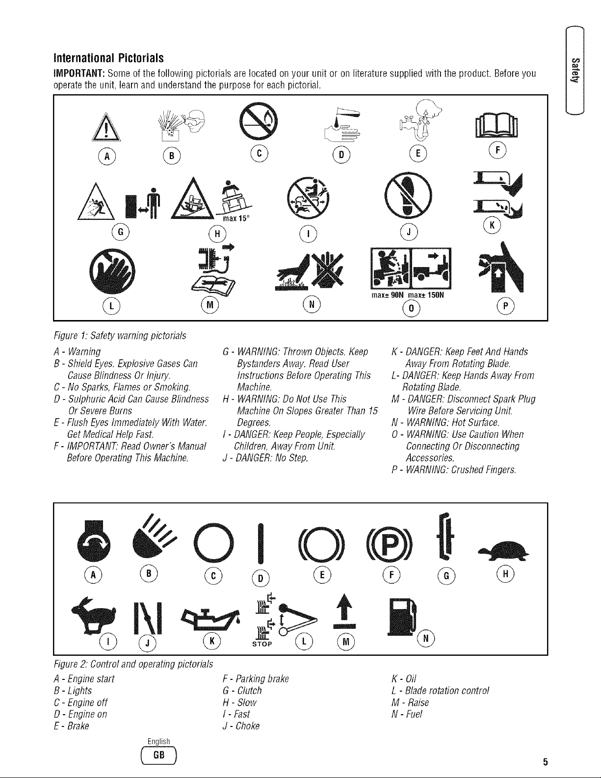
International Pictorials
IMPORTANT:Some of the following pictorials are located on your unit or on literature supplied with the product. Before you
operatethe unit, learn and understandthe purpose for each pictorial.
®
@ @
Figure 1: Safety warning pictorials
A - Warning
B- Shield Eyes,ExplosiveGasesCan
CauseBlindness Or Injury.
C- No Sparks,Flames or Smoking,
D- Sulphuric Acid Can CauseBlindness
Or SevereBurns
E- Flush EyesImmediately With Water.
GetMedical Help FasL
F- IMPORTANT:ReadOwner's Manual
BeforeOperating ThisMachine.
©
@
®
G- WARNING:Thrown Objects.Keep
BystandersAway. Read User
Instructions Before Operating This
Machine,
H - WARNING:Do Not Use This
Machine OnSlopes Greater Than 15
Degrees,
I- DANGER:KeepPeople, Especially
Children,Away From Unit.
J- DANGER:No Step.
®
,
@
db
max-*90Nmax-*150N
@
K - DANGER:KeepFeetAnd Hands
Away From Rotating Blade,
L- DANGER:KeepHandsAway From
Rotating Blade,
M- DANGER:Disconnect SparkPlug
WireBefore Servicing Unit.
N - WARNING:Hot Surface.
O- WARNING:Use Caution When
ConnectingOr Disconnecting
Accessories,
P - WARNING:Crushed Fingers.
@
0
@
Figure2."Controland operatingpictorials
A - Enginestart
B- Lights
C- Engine off
D- Engine on
E- Brake
English
C_
F - Parking brake
G - Clutch
H- Slow
I - Fast
J- Choke
®
K- Oil
L - Blade rotation control
M- Raise
N- Fuel
Page 8
==_
E
Assembly
_Read andfollow the assemblyand adjustment
instructionsfor yourmower.
Allfasteners are in theparts bag. Do notdiscard
anypartsor material untilthe unit
is assembled.
NOTE:In this instruction book, left and right describe the
location of a part with the operator on the seat.
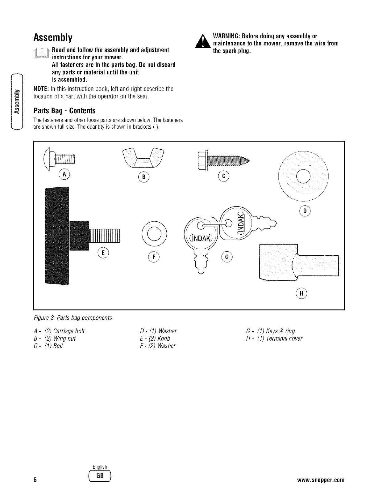
PartsBag- Contents
Thefasteners and other loose parts areshown below. Thefasteners
areshown full size. Thequantity is shown in brackets().
,_ WARNING:Beforedoinganyassemblyor
maintenancetothe mower, removethe wire from
thesparkplug.
@
Figure3; Parts bag components
A - (2) Carriagebolt
B- (2) Wing nut
C- (1) Bolt
D- (1) Washer
E- (2) Knob
F- (2) Washer
i!ili i il iiii
G- (1) Keys & ring
H- (1) Terminalcover
English
www.snapper.com
Page 9
Installingthe Seat
AssemblingtheSteering Wheel
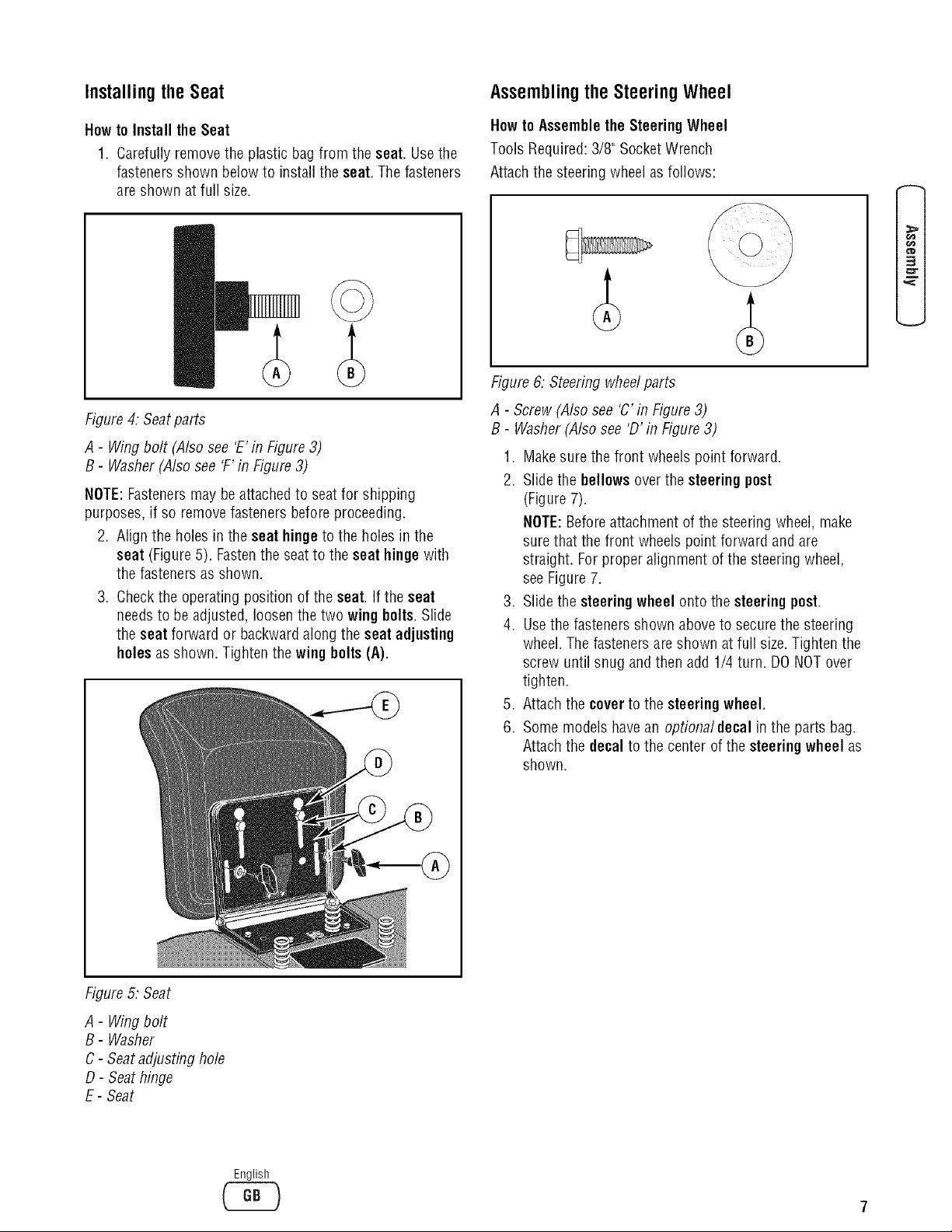
Howto Install the Seat
1. Carefully remove the plastic bag from the seat. Usethe
fasteners shown belowto install the seat. Thefasteners
are shown at full size.
Figure4: Seatparts
A- Wing bolt (Also see 'E'in Figure 3)
B- Washer (Also see 'F'in Figure 3)
NOTE:Fastenersmay be attachedto seat for shipping
purposes, if so remove fasteners before proceeding.
2. Align the holes in the seat hinge to the holes in the
seat (Figure5). Fastenthe seat to the seat hingewith
the fasteners as shown.
3. Checkthe operating position of the seat. If the seat
needsto be adjusted, loosen the two wing bolts.Slide
the seat forward or backward along the seat adjusting
holes as shown. Tighten the wing belts (A).
Howto AssembletheSteeringWheel
Tools Required:3/8" SocketWrench
Attachthe steering wheelas follows:
3
m
Figure 6."Steering wheelparts
A - Screw (Also see 'C' in Figure3)
B- Washer(Also see 'D' in Figure3)
1. Make sure the front wheels point forward.
2. Slide the bellows overthe steering post
(Figure 7).
NOTE:Beforeattachment of the steering wheel, make
surethat the front wheels point forward and are
straight. Forproper alignment of the steering wheel,
seeFigure 7.
3. Slidethe steeringwheel onto the steeringpost.
4. Usethe fasteners shown aboveto securethe steering
wheel. Thefasteners are shown at full size. Tighten the
screw until snug and then add 1/4 turn. DO NOTover
tighten.
5. Attachthe coverto the steeringwheel,
6. Some models havean optionaldecal in the parts bag.
Attachthe decalto the center ofthe steeringwheel as
shown.
Figure5."Seat
A - Wing bolt
B- Washer
C- Seatadjusting hole
D- Seat hinge
E- Seat
English
Page 10
==_
E
o_
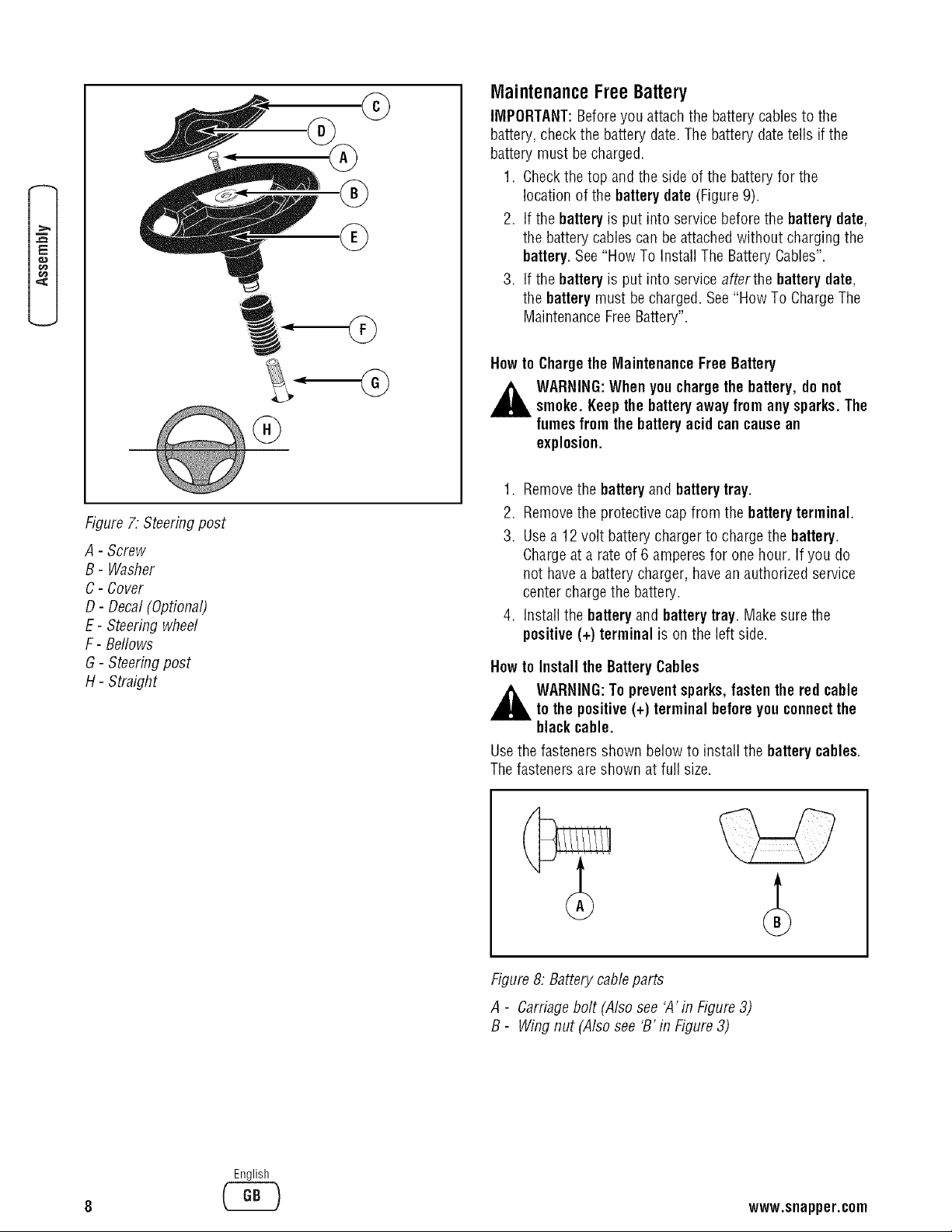
Figure7. Steeringpost
A - Screw
B- Washer
C- Cover
D- Decal (Optional)
E- Steering wheel
F- Bellows
G- Steeringpost
H- Straight
MaintenanceFreeBattery
IMPORTANT:Beforeyou attach the battery cables to the
battery, checkthe battery date. The battery date tells if the
battery must be charged.
1. Checkthe top and the side of the batteryfor the
location of the battery date (Figure9).
2. If the batteryis put into service before the battery date,
the battery cablescan be attached without charging the
battery. See"How To Install The BatteryCables".
3. If the batteryis put into service afterthe battery date,
the battery must becharged.See"How To ChargeThe
MaintenanceFreeBattery".
Howto Charge the Maintenance Free Battery
WARNING:Whenyouchargethe battery,do not
smoke. Keepthe batteryaway from any sparks.The
fumes from the batteryacid can cause an
explosion.
1. Removethe batteryand batterytray.
2. Removethe protective cap from the batteryterminal.
3. Usea 12 volt battery chargerto chargethe battery.
Chargeat a rate of 6 amperes for one hour. If you do
not havea battery charger, have an authorized service
center chargethe battery.
4. Installthe battery and battery tray. Makesure the
positive(+) terminal is on the leftside.
Howto Install the BatteryCables
_ ARNING:To preventsparks,fasten the redcable
tothe positive(+) terminal beforeyouconnect the
blackcable.
Usethe fasteners shown below to install the batterycables.
Thefasteners are shown at full size.
English
Figure 8: Batterycable parts
A - Carriagebolt (Also see 'A' in Figure3)
B- Wing nut (Also see 'B' in Figure3)
www.snapper.com
Page 11
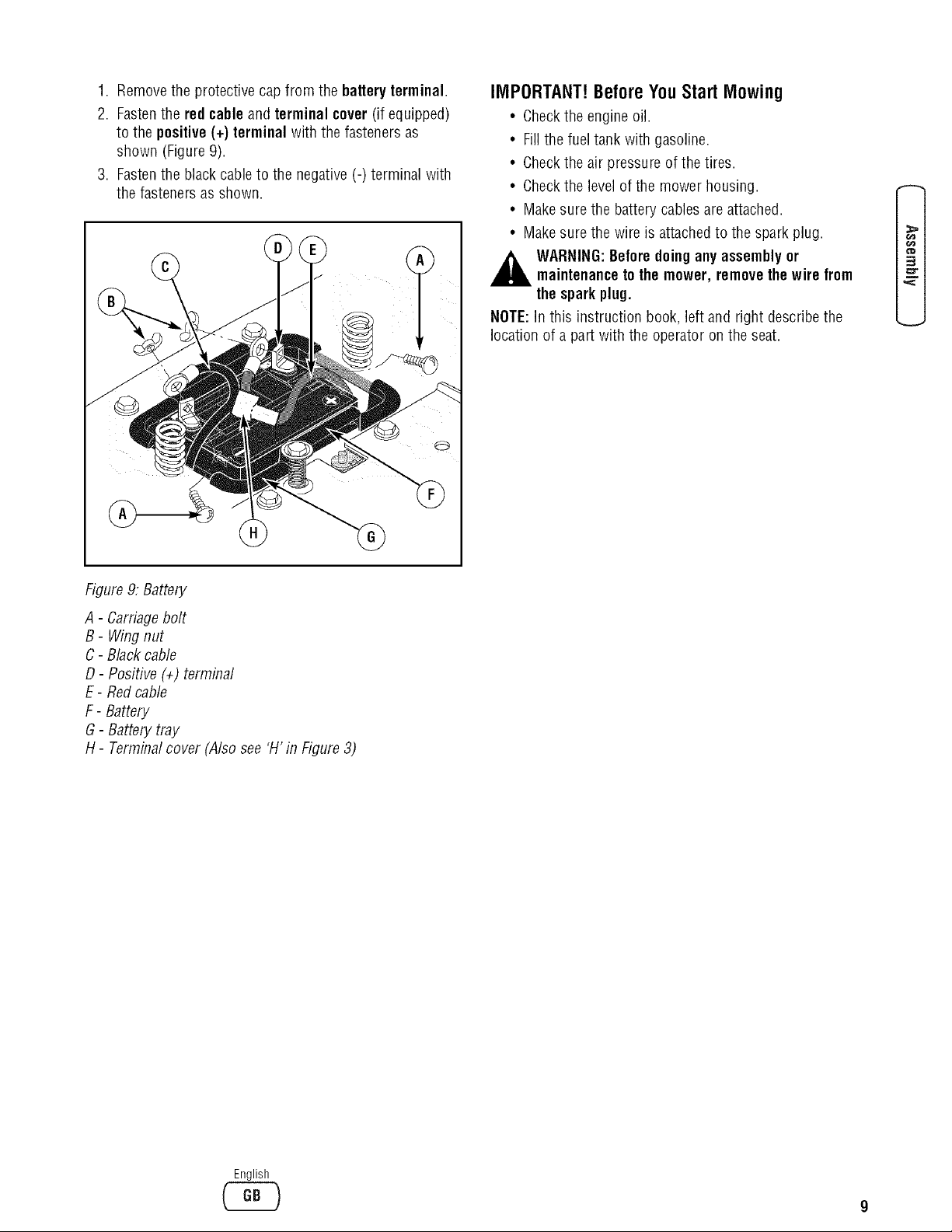
1. Remove the protective cap from the battery terminal.
2. Fastenthe red cable and terminal cover(if equipped)
to the positive (+) terminal with the fasteners as
shown (Figure9).
3. Fastenthe black cable to the negative (-) terminal with
the fasteners as shown.
IMPORTANT! Before You Start Mowing
• Checkthe engine oil.
• Fillthe fueltank with gasoline.
• Checkthe air pressure of the tires.
• Checkthe levelof the mower housing.
• Make surethe battery cablesareattached.
• Make surethe wire is attachedto the spark plug.
,_ WARNING:Beforedoingany assembly or
maintenancetothe mower, removethe wire from
thesparkplug.
NOTE:In this instruction book, left and right describe the
location of a part with the operator on the seat.
3
m
Figure9."Battery
A - Carriagebolt
B - Wing nut
C- Black cable
D- Positive (÷) terminal
E- Redcame
F- Battery
G- Battery tray
H- Termina/cover (A/so see 'H' in Figure 3)
English
Page 12
==_
E
Howto Prepare the Engine
NOTE:The engine was shipped from the factory filled with
oil. Checkthe level of the oil. Add oil as needed.
NOTE:The operation of a newengine will sometimes result
in a slight amount of smoke. This smoke is causedby paint
or oil on or around the muffler. This is normal and only
expectedduring initial operation.
A separateengine manualis also included with the unit. See
this engine manualfor the manufacturer's instructions for
thetype of gasolineand oil to use. Beforeyou usethe unit,
readthe information on safety, operation, maintenance,and
storage.
,_ WARNIN6: Followthe engine manufacturer's
instructionsfor thetype ofgasoline and oil to use.
Alwaysusea safety gasolinecontainer. Do not
smokewhen addinggasoline tothe engine. When
insidean enclosure,do not fill with gasoline.
Beforeyouadd gasoline, stopthe engine. Let the
enginecool for several minutes.
IMPORTANT:This unit is equipped with an internal
combustion engine and must not be used on or near any
unimproved forest-covered, brush-coveredor grass-covered
land unlessthe engine's exhaustsystem is equippedwith a
spark arrester meeting applicablelocal or state laws (if any).
If a spark arrester is used, it must be maintainedin effective
working order by the operator.
Inthe Stateof Californiathe above is required by law
(Section4442 of the California Public ResourcesCode).
Otherstates may have similar laws. Federallaws apply on
federal lands. Seean Authorized Service Centerfor a spark
arrester for the muffler.
Insome areas,local law requires the use of a resistor spark
plug to control the ignition signals. Seean Authorized
Service Centerfor a resistor spark plug for the engine.
NOTE:Actual sustained horsepower will likely be lower due
to operating limitations and environmental factors.
Checkthe Tires
NOTE:The tires may be overinflated for shipment.
Checkthe air pressure in the tires. Tires with too much air
pressure will causethe unit to ride rough. Also, the wrong
air pressure will keep the mower housing from cutting level.
Recommendedair pressure is 14 PSi (1 BAR).
Checkthe Level of the Mower Deck
Make surethe levelof cut is still correct. After you mow a
short distance, look at the areathat was cut. If the mower
deck does not cut level, seethe instructions on "How To
LevelThe Mower Deck" in the Maintenancesection of this
instruction book.
10
English
www.snapper.com
Page 13
FeaturesandControls
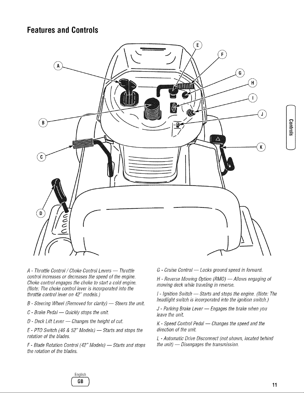
A - Throttle Control/Choke Control Levers-- Throttle
control increasesor decreasesthe speed of the engine,
Chokecontrol engagesthe choke to start a cold engine.
(Note: The chokecontrol lever is incorporated into the
throttle control lever on 42" models.)
B- Steering Wheel(Removedfor clarity) -- Steersthe unit.
C- Brake Pedal-- Quickly stops the unit.
D- Deck Lift Lever-- Changesthe height of cut.
E- PTOSwitch (46 & 52" Models) -- Starts and stops the
rotation of the blades,
F- BladeRotation Control (42" Models)-- Starts and stops
therotation of theblades.
English
G - CruiseControl -- Locks ground speed in forward.
H- ReverseMowing Option(RMO) -- Allows engaging of
mowing deck while traveling in reverse.
I- Ignition Switch -- Starts and stops the engine. (Note: The
headlight switch is incorporated into the ignition switch.)
J - Parking BrakeLever -- Engagesthebrake whenyou
leavethe unit.
K - SpeedControl Pedal-- Changesthe speedand the
direction of the unit.
L - Automatic Drive Disconnect (not shown, located behind
the unit) -- Disengagesthe transmission,
11
Page 14
Operation
Attachments
This unit can use many different attachments.
Forall pull-behind attachments or trailers, the maximum
gross weight is 250 pounds. Gross weight is the weight of
the attachment or trailer and any load that might be on or in
it.
Donot operateon a slope that is greater than 10 degrees
when using a pull-behind attachment or trailer. We have
included a slope guide in this bookto help you determine the
slope on which you will be operating your unit. Neverallow
someoneto stand or ride on or in an attachment or trailer.
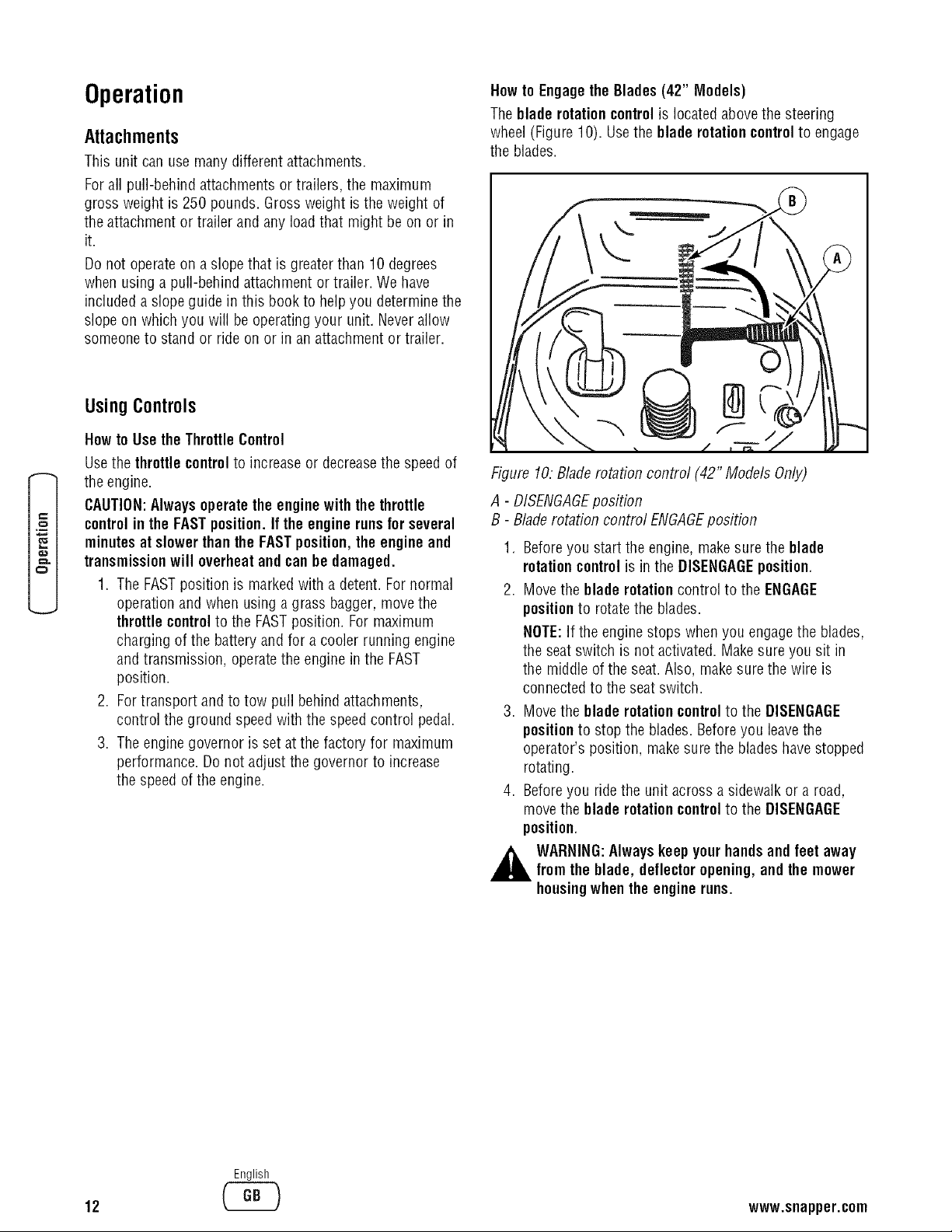
Howto EngagetheBlades (42" Models)
Theblade rotationcontrolis locatedabovethe steering
wheel (Figure 10). Usethe blade rotation controlto engage
the blades.
UsingControls
Howto Use the ThrottleControl
Usethe throttle controlto increase or decreasethe speedof
the engine.
CAUTION:Always operatethe engine withthe throttle
controlin the FASTposition.If the engine runs for several
e#
minutesat slower than the FASTposition,the engine and
transmission will overheatand can he damaged.
1. The FASTposition is markedwith a detent. Fornormal
operation and when using a grass bagger, movethe
throttle control to the FASTposition. For maximum
charging of the battery and for a cooler running engine
and transmission, operatethe engine in the FAST
position.
2. For transport and to tow pull behind attachments,
control the ground speed with the speed control pedal.
3. Theengine governor is set atthe factory for maximum
performance. Donot adjust the governor to increase
the speed of the engine.
Figure 10: Bladerotation control (42" Models Only)
A - DISENGAGEposition
B - Bladerotation control ENGAGEposition
1. Before you start the engine, makesure the blade
rotationcontrol is in the DISENGAGEposition.
2. Move the blade rotation control to the ENGAGE
positionto rotatethe blades.
NOTE:If the engine stops when you engagethe blades,
the seat switch is not activated. Makesure you sit in
the middle ofthe seat.Also, makesure the wire is
connectedto the seat switch.
3. Movethe blade rotationcontrolto the DISENGAGE
positionto stop the blades. Beforeyou leavethe
operator's position, makesure the blades havestopped
rotating.
4. Beforeyou ride the unit across a sidewalk or a road,
move the blade rotationcontrolto the DISENGAGE
position.
12
English
,_ WARNING:Alwayskeepyourhandsandfeet away
fromthe blade, deflectoropening, andthe mower
housingwhen the engineruns.
www.snapper.com
Page 15
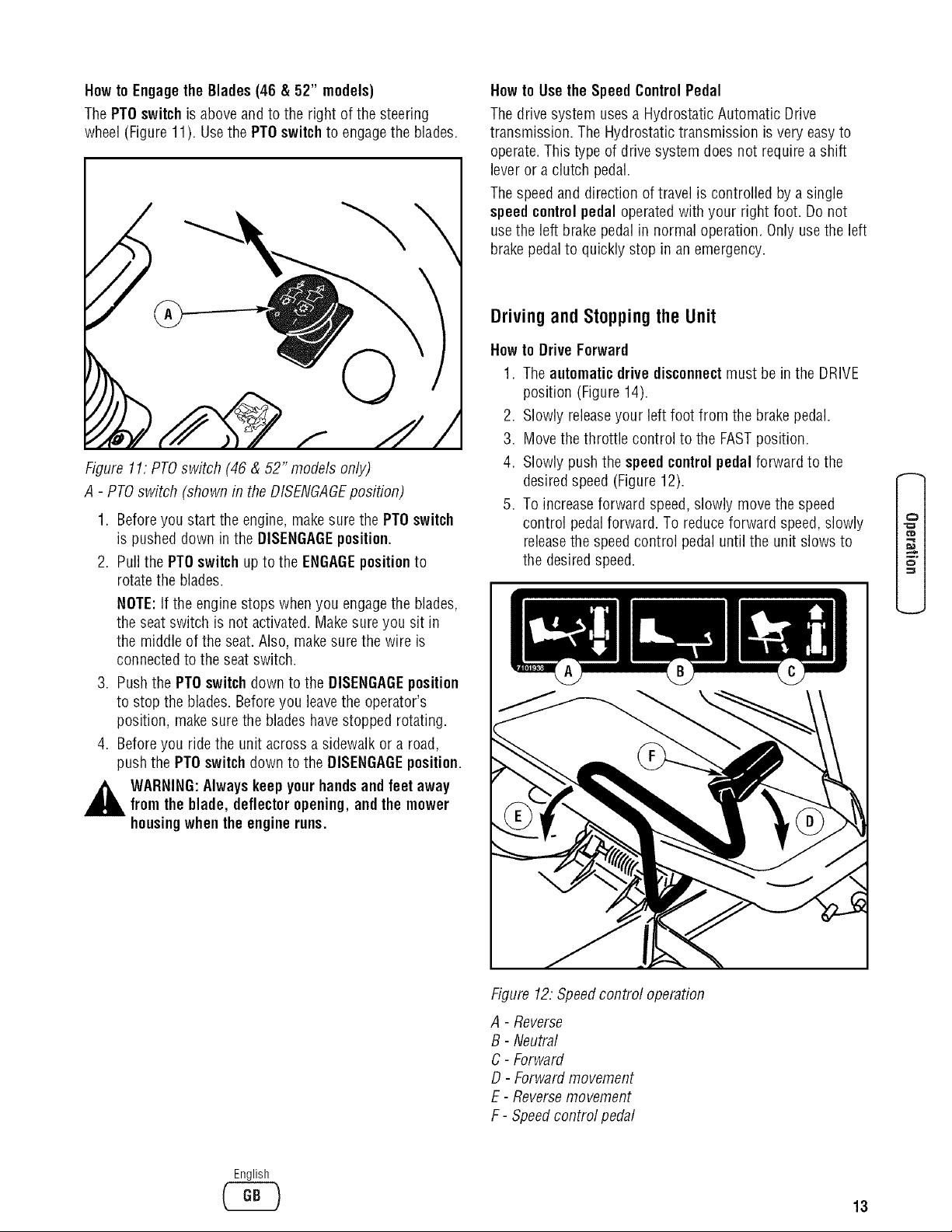
Howto EngagetheBlades (46 & 52" models)
ThePTO switchis above and to the right of the steering
wheel (Figure 11). Usethe PTDswitchto engagethe blades.
\
Figure 11: PTOswitch (46 & 52"models only)
A - PTOswitch (shown in the DISENGAGEposition)
1. Before you start the engine, makesurethe PTDswitch
is pushed down in the DISENGAGEposition.
2. Pui] the PTOswitchup to the ENGAGEpositionto
rotate the blades.
NOTE:If the engine stops when you engagethe blades,
the seat switch is not activated. Makesureyou sit in
the middle of the seat.Also, makesure the wire is
connectedto the seat switch.
3. Pushthe PTOswitchdown to the DISENGAGEposition
to stop the blades. Beforeyou leavethe operator's
position, makesure the blades havestopped rotating.
4. Beforeyou ride the unit across a sidewalk or a road,
push the PTOswitchdown to the DISENGAGEposition.
Howto Use the Speed ControlPedal
Thedrive system usesa Hydrostatic Automatic Drive
transmission. The Hydrostatic transmission is very easyto
operate.This type of drive system does not require a shift
lever or a clutch pedal.
Thespeed and direction of travel is controlled by a single
speedcontrol pedal operatedwith your right foot. Do not
usethe left brakepedal in normal operation. Only usethe left
brakepedal to quickly stop in an emergency.
Driving and Stopping the Unit
Howto Drive Forward
1. The automaticdrive disconnectmust be in the DRIVE
position (Figure14).
2. Slowly releaseyour left foot from the brakepedal.
3. Movethe throttle control to the FASTposition.
4. Slowly push the speedcontrol pedal forward to the
desiredspeed (Figure 12).
5. To increaseforward speed, slowly move the speed
control pedalforward. To reduceforward speed, slowly
releasethe speedcontrol pedal until the unit slows to
the desired speed. o
,_ WARNING:Always keep pourhandsand feet away
fromthe blade, deflectoropening, andthe mower
housingwhen the engineruns.
English
Figure 12: Speedcontrol operation
A - Reverse
B - Neutral
C- Forward
D - Forward movement
E - Reversemovement
F- Speedcontrol pedal
13
Page 16

Howto Use the CruiseControl
To engagethe cruise control:
1. Slowly push the speedcontrol pedal forward to the
desiredspeed (Figure 12).
2. Pull up on the cruise control knob(Figure 13). Release
the speedcontrol pedal. Theunit should continue
traveling forward atthe desiredspeed.
NOTE:The cruise control only operates in forward
speeds.
To disengagethe cruise control:
1. Push the speed controlpedal (Figure 12), OR
2. Push the brakepedal.
WARNING:Do notengagethe cruisecontrolwhen
drivingon slopes,or whenpeople oranimals are in
the vicinity.
\
Howto Drive in Reverse
1. Look to the rear.
2. Slowly push the speedcontrolpedalto the REVERSE
position.
Howto ChangeDirection
CAUTION:To changedirections,do not usethe left brake
pedal. Useonly the speedcontrol pedal.
1. Slowly remove your foot from the speedcontrol pedal.
Thespeedcontrol pedalwill automatically return to the
NEUTRALposition.
2. When the unit stops, slowly move the speedcontrol
pedalto the desired direction.
SpeedControl Pedal Positions
Theforward speed is controlled by the position of the speed
controlpedal. The following chart provides functions along
with the pedal positions.Always operatethe engine with the
throttlecontrolin the FASTposition.
Function
Pedal Positon
ThrottlePosition
Trimming
Snow Thrower
e#
Figure 13."Cruisecontrol
A - Cruise Control knob
Bagging Grass
Normal Mowing
EasyMowing
Snow Blade
Transport
Pull Behind
Attachments
Howto Disconnectthe Transmission
To push the unit, use the automaticdrivedisconnectto
releasethe transmission. Theautomaticdrive disconnectis
located on the right rear of the unit.
1. The engine must be off.
2. Pull out and lock the automatic drivedisconnectin the
PUSHposition (Figure13). Thetransmission is now
releasedand the unit can be pushed.
NOTE:in cold weather,the heavyviscosity oil in the
transmission will makethe unit difficult to push.
3. To engagethe transmission, unlock and push in the
automaticdrive disconnect.Thetransmission is now
connectedand readyto operate.
1/3
1/3 to 1/2
1/2 to 2/3
1/2 to 3/4
FULL
1/3 to 1/2
FastThrottle
14
English
www.snapper.com
Page 17

Figure 13:Automatic drive disconnect
A - Automatic drive disconnect DRIVEposition
B - Automatic drive disconnect PUSHposition
C- Automatic drive disconnect
Howto Set the ParkingBrake
1. Completely push the brake pedal forward.
2. Lift the parkingbrake lever (Figure 14).
3. Removeyour foot from the brakepedaland then
releasethe parkingbrakelever. Make sure the parking
brakewill hold the unit.
4. To releasethe parking brake, completely push the brake
pedal forward. The parking brake will automatically
release.
WARNING:Beforeyouleave the operator's position,
movethe speed control pedal to the neutral (N)
position.Set the parkingbrake. Movethe blade
rotationcontroltothe DISENGAGEposition.Stopthe
engineandremovethe ignitionkey.
Howto Change the Cutting Height
To changethe cutting height, raiseor lower the deckift
lever as follows:
1. Move the deck lift lever forward to lower the mower
housing and backto raisethe mower deck (Figure 15).
2. When you ride on a sidewalk or road, move the deck lift
leverto the highest position and disengage the blades
(Figures 10, 11).
o
Figure 15: Lift control
A - Decklift lever
Howto Stop the Unit
1. Slowly remove your foot from the speed control pedal.
Thespeed control pedal will automatically return to the
NEUTRALposition and the unit will stop.
2. Move the blade rotation control to the DISENGAGE
position.
3. Setthe parking brake.
Figure 14: Parkingbrake
A - Brakepedal
B - Parkingbrake lever
,_ WARNING:Make surethe parkingbrakewill holdtheunit.
4. Movethe throttle control to the SLOWposition.
5. To stop the engine, turn the ignition key to the OFF
position. Removethe key.
English
15
Page 18

Nowto Transportthe Unit
ReverseMowingOption (RMO)
Totransport the unit, follow the steps below.
,_ WARNING:Mowingin reversecan be hazardousto
1. Disengagethe blades.
2. Raisethe deck lift leverto the highest position.
3. Movethe throttle control to the FASTposition.
4. Slowly push the speed control pedalforward to the
desiredspeed.
bystanders. Tragicaccidentscan occur if the
operator is notalert tothe presenceof children.
Never activateRMO if children arepresent.
Childrenare oftenattractedtothe unitand the
mowingactivity.
1. Engagethe blades.
2. Insert the supplied key into the RMD swilch, locatedto
the right of the steering wheelbellows (Figure 16).
Mowing
3. Turn the key. The L.E.D.light will illuminate, indicating
thet the RMOfeature has beenactivated. The mower
Howto Operatethe MowerDeck
deck can now be operatedwhile the unit istraveling in
reverse.
&WARNING: The deflectoris a safety device. Do notremovethe deflector.The deflectorforcesthe
dischargedmaterialtoward the ground. Always
keepthe deflectorin thedown position.If the
deflectoris damaged,replace the deflectorwith an
originalequipmentpart from an authorizedservice
4. Thereverse mowing option is deactivatedwhen the
bladesare disengaged,and must be reactivatedeach
time the blades are engaged,if desired.
5. Removethe key to restrict accessto the RMOfeature.
center.
&WARNING: The enginewill shutoff if the speed
1. Start the engine.
control pedalis movedintoreversewhile the
bladesare engagedandthe RMOis notactivated.
2. Releasethe parking brake.
3. Movethe deck lift leverto a height of cut position. In
e#
high or thick grass, cut the grass in the highest
position first and then lower the mower deck to a lower
position.
CAUTION:Do notoperatewith the mowerdeckin the
LEVELADJUSTMENTposition.If youoperatein the LEVEL
ADJUSTMENTposition,the mower deckand bladescan be
damaged.
4. Movethe throttle control to the SLOW position.
5. Engagethe blades.
6. Movethe throttle control to the FASTposition.
7. Slowly push the speed control pedalto the desired
speed.
NOTE:When you mow in heavygrass or mow with a
grass bagger, use a slow forward speed.
8. Make sure the level of cut set at the factory is still
correct. After you mow a short distance, look atthe
areathat was cut. if the mower deck does not cut level,
seethe instructions on "How To LevelThe Mower
Deck" in the Maintenancesection.
Figure 16: ReverseMowing Option (RMO)
A - Key
,_ WARNING:Forbetter controlof the unit, always
select a safe speed.
B - RMO switch
C- L,E.D,light
16
English
www.snapper.com
Page 19

Howto Operate the Unit on Hills
,_ WARNING:Do not ride upor downslopesthat are
too steepto backstraightup. Never ridethe unit
acrossa slope. See the "Slope 6uide" in the back
of this bookfor informationon howto check slopes.
1. Control the speed only with the speed control pedal. Do
not use the brake pedal on a hill.
2. To help prevent an accident, slowly movethe speed
control pedal. Avoid suddenturns or changesin speed.
3. To reduceforward speed when going down a hill,
slowly releasethe speed control pedal until the unit
slows to the desired speed.
Howto Stopon a Hill
1. Avoid stopping on a hill. If you must quickly stop inan
emergency, removeyour right foot from the speed
control pedal and quickly depressthe left brakepedal.
2. Set the parking brake.
3. Beforeyou dismount from the seat, movethe throttle
control to SLOW position, move the blade rotation
control to the DISENGAGEDposition, turn off the
engine and set the parking brake.
Howto Start Operationon a Hill
1. Start the engine.
2. Move the blade rotation control to the ENGAGED
position.
3. Movethe throttle control to the FASTposition.
4. Depressthe brake pedal and releasethe parking brake.
Asyou releasethe parking brake,push the speed
control pedal to the desiredspeed.
CD
o
,_ WARNIN6: Slowly pushthe speedcontrol pedal as
you release the parkingbrake.The parkingbrake
mustbe disengagedbeforethe speed controlpedal
is able to engagethe transmission.
English
17
Page 20

EngineOperation
BeforeStartingthe Engine
Checkthe Oil
Carburetor
Do not attempt to adjust the carburator. Engineadjustments
and repairs should be performed only by an authorized
dealer.
NOTE:The engine was shipped from the factory filled with
oil. Checkthe level of the oil. Add oil as needed.Seethe
engine manufacturer's instructions for the type of gasoline
and oil to use.
1. Make sure the unit is level.
NOTE:Do not check the level of the oil while the engine
runs.
2. Checkthe oil. Followthe procedure in the engine
manufacturer's instructions.
3. If necessary, add oil until the oil reachesthe FULLmark
on the dipstick. The quantity of oil neededfrom ADDto
FULLis shown on the dipstick. Do not add too much
oil.
Howto Start the Engine
WARNING:The electrical systemhasan operator
presencesystemthat includesa sensorswitchfor
theseat. These components tell the electrical
systemif the operatoris sitting ontheseat. This
systemwill stopthe enginewhen the operator
leavesthe seat. For yourprotection,alwaysmake
surethis systemoperatescorrectly.
NOTE:The engine will not start unless you depressthe brake
pedal or engagethe parking brakeand disengagethe blades.
1. Push the brake pedal completely forward. Keepyour
foot on the pedal.
AddGasoline
2. Make sure the blades are disengaged.
3. Movethe throttle control completely forward to the
,_ WARNING:Alwaysusea safetygasolinecontainer.
Donot smokewhen addinggasolineto the fuel
tank. Do notadd gasolinewhen youare inside an
enclosure.Beforeyouadd gasoline, stopthe
e#
engineand let the enginecoolfor several minutes.
Fillthe fueltank with regular unleadedgasoline. Do not use
premium unleadedgasoline. Makesure the gasoline is fresh
and clean. Leadedgasolinewill increasedeposits and
shorten the life of the valves.
FASTposition.
4. Movethe choke control completely forward.
NOTE:On42" Models, the choke is incorporated into
the throttle control. Move the throttle control past the
FASTposition to the CHOKEposition.
5. Turn the ignition key to the STARTposition. Release
the key when the enginestarts.
NOTE:If the engine does not start after four or five
tries, see the TROUBLESHOOTINGCHART.
6. Turn off the choke, and slowly move the throttle control
to the SLOWposition.
7. Let a cold engine run for several minutes. Begin work
\
when the engine is warm. To start a hot engine, move
the throttle control to a position between FASTand
SLOW.
Figure 17: Gastank
A - Fueltank
B- Fullline
CAUTION:Amixtureof alcohol(ethanol or methanol)and
gasoline(called gasohol),will attract moistureand cause
acid depositsduringstorage.While the unit is in storage,
theacids in the fuel can damagethefuel system.
To prevent engine problems with the fuel system, empty the
fuel system before storage of 30 days or longer as follows.
1. Drain the fuel tank.
2. Start the engine.Let the engine run until the fuel lines
and the carburetor are empty.
3. After storage, makesure you usefresh fuel. Seethe
storage instructions for additional information.
4. Neveruse engine cleaneror carburetor cleaner in the
fuel tank or permanent damagecan occur.
English
18
www.snapper.com
Page 21

Tips
OperatingTips
1. Checkthe blade rotation control or the PTOclutch for
correct adjustment. Forthe bladesto disengage
correctly, the adjustment must be correct.
2. Before you use the unit, check the oil in the engine and
add oil if necessary.
3. If the engine will not start, first makesure the wire is
attachedto the spark plug.
4. Makesure all the belts are inside all the belt guides.
Seethe instructions on how to removeand install the
motion drive and mower drive belts.
5. Beforeyou makean inspection, adjustment (except for
the carburetor), or repair, makesure the wire from the
spark plug is disconnected.
6. For longer life of the battery on electric start models,
chargethe battery every three months.
7. Usethe speedcontrol pedal to changethe ground
speed, not the throttle control.
8. Belt noisecan occur when the blade is engaged.This
noise is normal and does not affect the operation of the
unit.
Mowingand BaggingTips
1. For a lawnto look better, checkthe cutting level of the
mower deck. See"How To LevelThe Mower Deck"in
the Maintenancesection.
2. For the mower deck to cut level, make surethe tires
havethe correct amount of air pressure.
3. Everytime you usethe unit, checkthe blade. If the
blade is bent or damaged, immediately replacethe
blade.Also, make sure the nut for the blade is tight.
4. Keepthe bladessharpened.Worn bladeswill cause the
ends of the grass to turn brown.
5. Do not cut or bag grassthat is wet. Wet grass will not
discharge correctly. Let the grass dry beforecutting.
6. Usethe left side of the mower deck to trim near an
object.
7. Discharge the cut grass onto the mowed area.The
result is a more evendischarge of cut grass.
8. When you mow large areas,start by turning to the right
so that the cut grass will discharge away from shrubs,
fences, driveways,etc. After one or two rounds, mow in
the opposite direction making left turns until finished
(Figure 18).
Figure 18: Mowing tips
9. If the grass is very high, cut two times to decreasethe
load on the engine. Firstcut with the mower housing in
the highest position and then lower the mower housing
for the second cut.
10. For better engine performanceand an even discharge of
the cut grass, alwaysoperate the engine with the
throttle in FASTposition.
11. When you use a bagger,operate the engine with the
throttle in FASTposition andthe speedcontrol pedal
pushed 1/3 forward.
12. For better cutting performance and a quality cut, mow
with the speed control pedal pushed 1/3 to 1/2 forward.
13. After each use, cleanthe bottom and top of the mower
housing for better performance. Also, a cleanmower
housing will help prevent a fire.
o
English
lg
Page 22

Maintenance
MaintenanceSchedule
Frequency MaintenanceRequired Comments
Daily or before each use Maintenanceengine. Referto the EngineOwner's Manual.
Examineblades. Checkfor cracks, wear, and excessive damage.
Removedebris from unit and mowing area.
Examineall rotating and sliding parts.
Checktire inflation. Referto the Maintenancesection.
Verify that the mower deck is level. Referto the Maintenancesection.
ExamineV-belts. Checkfor cracks, wear, and excessive damage.
Checkbrake operation. Referto the Operationand Maintenance
sections.
After completion of first Changeoil. Referto the EngineOwner's Manual.
5 hours
After 25 hours Maintenanceengine. Referto the EngineOwner's Manual.
Remove,examine,sharpen, and balance Referto Maintenancesection.
blades.
el#
e#
e#
5=
Checkadjustments: Referto Maintenancesection.
a. Blade Rotation Control or PTOClutch
b. Brake
c. Steering
Lubricate chassis and mower deck. Referto Whereto Lubricate instructions.
Referto Maintenancesection.Checkthe muffler:
a.Torque
b. For wearor burn out
c. Condition of spark arrestor
(if applicable).
Beforestorage of 30 Referto the EngineOwner's Manual.
days or more Referto warnings in the Owner's Manual.
Prepareengine for storage.
Drain fuel system.
Add fuel stabilizer.
Referto the EngineOwner's Manual.
Preparebattery for storage:
a. Removefrom unit.
b. Fullycharge.
c. Move to cool dry place.
20
English
www.snapper.com
Page 23

GeneralRecommendations
1. The owner's responsibility is to maintainthis product.
This will extendthe life of the product and is also
necessaryto maintainwarranty coverage.
2. Checkthe spark plug, drive brake, lubricate the unit,
and cleanthe air filter oncea year.
3. Checkthe fasteners. Make sureall fasteners are tight.
4. Followthe Maintenancesection to keepthe unit in good
operating condition.
WARNING:Beforeyou make an inspection,
adjustment,or repair to the unit, disconnectthe
wire tothe sparkplug. Removethe wire from the
spark plugto preventtheengine from starting by
accident.
NOTE:Torque is measuredin foot pounds (metric Nm). This
measurementdescribeshow tight a nut or bolt must be. The
torque is measuredwith a torque wrench.
Inspection
Howto Check the Muffler
Checkthe muffler every50 hours. Makesure the muffler is
correctly mounted and is not loose. If the muffler is worn or
burnt, replacewith a new muffler. A worn muffler is afire
hazardand can also damagethe engine.
If you mount a spark arrester to the muffler, also check the
spark arrester whenyou check the muffler. If the spark
arrester is worn or damaged,replaceit with a new spark
arrester. Seeyour nearestauthorized servicecenterfor a
spark arrester.
InspectBlade
,,_ WARNING:Beforeyouinspector removetheblade,
disconnectthewire tothe sparkplug.If thebladehits
anobject, stoptheengine.Checkthe unitfor
damage.Thebladehassharpedges.Whenyouhold
the blade,useglovesorcloth materialto protectyour
hands.
If you keepthe bladesharp and inspectthe bladefor
damage,the blade will cut better and be more safe to
operate. Frequentlycheck the bladefor excessivewear,
cracks, or other damage. Frequentlycheck the nut that holds
the blade. Keepthe nut tight. If the blade hits an object, stop
the engine. Disconnectthe wire to the spark plug. Seeif the
blade is bent or damaged. Checkthe blade adapterfor
damage. Beforeyou operatethe unit, replacedamaged parts
with original equipment parts. Seethe authorized service
center in your area. Everythree years, havean authorized
serviceperson inspect the blade or replacethe old blade with
an original equipment part.
Howto Removeand Install the Blade
1. Remove the mower housing. Seethe instructions on
"How To RemoveThe Mower Housing".
2. Usea piece of wood to keepthe bladefrom rotating.
3. Removethe nutthat holds the blade (Figure 19).
Figure 19: Removing the blades
A - Hi-lift edge up
B- Blade
C- Belleville washer
D - Nut
E- Washer
F - Bladeadapter
G- Mandrel
4. Checkthe blade and the blade adapteraccording to
the instructions for "Inspect Blade". Replacea badly
worn or damaged bladewith an original equipment
blade. Seean authorized service center in your area.
5. Cleanthe top and bottom of the mower housing.
Removeall the grass and debris.
6. Mount the blade and blade adapter on the mandrel
(Figure 19).
7. Mount the blade so that the hi-lift edges are up. If the
blade is upside down, the blade will not cut correctly
and can causean accident.
8. Fastenthe blade with the original washers and nut.
Make surethe outside rim of the Belleville washer is
against the blade (Figure 20).
WARNING:Always keepthe nuttightthat holdsthe
blade. A loose nutor bladecan causean accident.
9. Tightenthe nut that holds the bladeto a torque of 35
foot pounds (47,5 N-m).
English
21
Page 24

el#
e#
e#
5=
10. Install the mower deck. See"How To Install The Mower
Deck".
©
Figure20: Bladeassembly
A - Bladeadapter
B- Bellevillewasher(Outsidenm must beagainstthe blade,)
C- Nut
D- Washer
E- Blade
Howto Sharpenthe Blade
_ ARNING:Vibrationcan be caused if the blade is
notcorrectlybalancedor ifthe bladeis damaged.A
bladethat is damagedwith crackscan breakand
cause an accident.
Keepa sharp edge on the blade. A bladethat is not sharp
will causethe tips of the grass to become brown.
1. Sharpenthe blade two times a year or every 25 hours.
2. Remove the blade according to the instructions in
"How To RemoveAnd Install The Blade".
3. Cleanthe blade with a brush, soap and water. Check
the blade. Look for cracks, nicks, or other damage.
Replacea badly worn or damagedbladewith an
original equipment blade.Seean authorized service
center in your area.
4. Sharpenthe bladewith a file (Figure21). Makesure
you keep the original bevel angle.
5. Makesure the blade is balanced.Usea screwdriver
and hold the blade parallelto the ground (Figure 21). A
blade that is balancedwill stay parallelto the ground. If
the blade is not balanced,the heavyend will rotate
toward the ground. Sharpenthe heavyend until the
blade is balanced.
6. A new blade will cut better than a badlyworn blade.
Everythree years, havean authorized service person
inspect the blade or replacethe old bladewith an
original equipment blade.
7. Assemblethe blade according to the instructions "How
To RemoveAnd Install The Blade".
m !
@
Figure21: Sharpening the blades
A - Screwdriver
B- Blade
C- File
D- Ground
E - Blade is balanced whenparallel to the ground
Adjustments
Howto Adjustthe BladeRotationControl(42" Models)
,_ WARNING:To preventaninjury, the blade rotation
controlmust operatecorrectly.
In normal usage,the blade rotationcontrolwill not require
an adjustment. However,if the cutting performance
decreasesor the quality of cut is poor, makethe following
changes.
1. When you mow, makesure the throttle control in in the
FASTposition.
2. Move the blade rotation control to the DISENGAGE
position(Figure22).
3. Stop the engine. Disconnectthe wire from the spark
plug.
22
English
www.snapper.com
Page 25

Figure22: Bladeadjustments
A - DISENGAGEPosition
B - BladeRotation Control ENGAGEPosition
4. Checkthe blade(s). Keepa sharp edge on the blade(s).
A blade that is not sharp will causethe tips of the grass
to becomebrown.
5. Loosenthe hardware securing the bladeengagecable
bracket (Figure 23) to the mower deck. Slide the
bracketforward 1/4 - 1/2". Tightenthe hardware
securely.
6. Attachthe wire to the spark plug. Mow for a short
distanceand againcheck the quality of cut. If
necessary,readjust the blade engagecablebracket.
7. Again check the quality of cut. If the quality of cut has
not improved, replacethe mower drivebelt. See"How
To ReplaceThe Mower Drive Belt". If replacingthe belt
does not correct the problem, take the unit to an
authorized servicecenter.
8. Move the blade rotation controlto the DISENGAGE
position. Stop the engine. Disconnectthe wire from the
spark plug. Checkthe operation ofthe blade brake.
Rotatethe pulleys with your hand. Makesure the brake
pads are pressedtightly against the pulleys (Figure24).
,_ WARNING:If the brake padsdo notpresstightly
againstthe pulleys,take the unitto an authorized
servicecenter.
Figure23. Bladeengagecableadjustment
A - Bladeengagecable bracket
Figure24: Bladebrake
¢D
A - Brakepad against pulley
9. Movethe blade rotationcontrolto the ENGAGE
position.Checkthe pads for the blade brake.If the
padsare excessivelyworn or damaged,replacethe
brake padassemblies. Correct replacement parts and
assistanceare availablefrom an authorized service
center.
10. Attach the wire to the spark plug. Mow for a short
distanceand againcheck the operation of the blade
rotation control.
11. When you move the blade rotation controlto the
DISENGAGEposition,all movementwill stop within five
seconds. If there is movement of the belt or the blades
continue to rotate, engageand disengagethe blade
rotation controlfive times to remove any excess rubber
from a new mowerdrive belt. If you needassistance,
takethe unit to an authorized service center.
12. If you replacethe mowerdrivebelt, be sure to adjust
the bladeengage cable bracket.
English
23
Page 26

el#
e#
e#
5=
Howto Check and Adjustthe PTOClutch
(46 & 52" Models)
Checkthe PTOclutch adjustment after the initial 25 hour
break-in period and then after every 250 hours of operation.
Also perform the following procedure if the clutch is slipping
or will not engage,or if a new clutch hasbeen installed.
,_ WARNING:Beforeyou make an inspection,
adjustment,or repair to the unit, disconnectthe
wire tothe sparkplug. Removethe wire from the
spark plugto preventtheengine from starting by
accident.
1. Remove key from ignition switch and disconnect spark
plug wires to prevent the possibility of accidental
starting while the PTOis being adjusted.
2. Note the position of the 3 adjustment windows (A,
Figures25 & 26) in the side of the brake plate and the
nyiock adjustment nuts (B).
3. Insert a .016"-.018" (0,40-0,45mm) feeler gauge (C,
Figure26) through eachwindow, positioning the gauge
betweenthe rotor faceand the armature face as shown.
4. Alternatelytighten the adjustment nuts (B) until the
rotor face and armature face just contacts the gauge.
5. Checkthe windows for an equal amount of tension
whenthe gauge is inserted and removed, and makeany
necessaryadjustments by tightening or looseningthe
adjustment nuts.
NOTE:The actual air gap betweenthe rotor and
armature may vary evenafter performing the
adjustment procedure. This is dueto dimensional
variations on component parts, and is an acceptable
condition.
6. Checkthe mower bladestopping time. The mower
bladesand mower drive belt should come to a
complete stop within five seconds after the electric PTO
switch is turned off.
Figure26: PTOclutch adjustment
A - Adjustment window
B- Adjustment nut
C- .016"-,018" (0,40-0,45mm) feeler gauge
BladeBrakeCheck (46 & 52" ModelsOnly)
Mower bladesand mower drive beltshould come to a
complete stop within five seconds after electric PTOswitch
is turned off.
1. With parking brakeengaged, PTOdisengagedand an
operator in the seat,start the engine.
2. Havean assistant observethe mower drive belt through
the opening betweenthe frame and top of mower deck.
Engagethe PTOand wait severalseconds. Disengage
the PTOand checkthe amount of time it takesfor the
mower drive belt to stop.
3. If the mower drive belt doesnot stop within five
seconds, perform the PTOClutchAdjustment. Ifthe
belt still does not stop within 5 seconds, see your
dealer.
Figure25: PTOclutch
A- Adjustment window (3)
B- Adjustment nut
English
24
www.snapper.com
Page 27

Howto Checkand Adjustthe MotionDrive Belt
If the motion drive belt is loose,the belt will slip when; (1)
going up a hill, (2) pulling a heavyload, or (3) the unit will
not move forward. Adjust the belt as follows.
,_ WARNING:Beforeyou make an inspection,
adjustment,or repair to the unit, disconnectthe
wire tothe sparkplug. Removethe wire from the
spark plugto preventtheengine from starting by
accident.
1. Checkthe routing of the motion drive belt. Makesure
the belt is installed correctly and is inside all the belt
guides.
2. Disconnect the clutchlink from the idler arm (Figure
27).
3. Alignthe hole in the brake lever with the hole in the
frame. Hold the brake lever in placewith a 1/4 inch (6
mm) pinor bolt (Figure28).
4. Rotatethe clutch link until the mounting hole in the
clutchlink is alignedwith the hole in the idler armas
shown in Figure27.
5. Connectthe clutchlinkto the idler arm
(Figure27).
6. Removethe 1/4 inch(6 mm) pin or bolt
(Figure28).
o
Figure27."Aligning clutch link
A - Mounting holes
B- Idler arm
C- Clutch link
D - Clutch rod
7. If the belt still slips after the belt has beenadjusted,
thenthe motion drive belt is worn or damagedand
must be replaced. See"Replacing The Motion
Drive Belt".
Figure28: Adjusting motion drive belt
A - 1/4"(6mm) Pin or bolt
B- Clutch link
C- Idler arm
D- Idler spring
¢D
¢D
E - Motbn drive belt
F - Belt guide
G- Brakelever
English
25
Page 28

MaintenanceFreeBattery
Howto Removethe Battery
To charge or cleanthe battery, removethe battery from the
unit as follows.
_ ARNING:Topreventsparks,disconnecttheblack
batterycable from the negative(-) terminal before
you disconnectthe red cable.
WARNING:The batterycontains sulfuricacid which
is harmfulto the skin, eyes, andclothing. If the
acid getson the bodyor clothing, washwith water.
1. Disconnect the blackcable from the negative(-)
terminal (Figure 29).
2. Disconnect the red cable from the positive(+)
terminal.
3. Liftthe batterytray andthe batteryout of the unit.
Howto Clean the Battery
1. Remove the battery.
2. Wash the battery with a solution of one gallon of water
and four tablespoons of baking soda (sodium
bicarbonate). Makesure the solution does not get into
the battery cells.
3. Cleanthe terminals and the ends of the cableswith a
wire brush.
4. Install the battery.
5. To prevent corrosion, apply greaseto the battery
terminals.
Figure29: Battery
A - Carriagebo/t
B - Wingnut
C- Black cable
D- Positive (+) terminal
E- Redcable
F- Battery
G - Battery tray
H- Terminal cover
Howto Charge the Battery
_ ARNING:Whenyouchargethe battery,do not
smoke. Keepthe batteryaway from any sparks.The
fumes from the batteryacid can cause an
explosion.
1. Before you charge the battery, removethe battery.
2. To chargethe battery, usea 12 volt battery charger.
Chargeat a rate of 6 amperes for 1 hour.
3. Install the battery.
,_ WARNING:To preventsparks, fasten the red cable
to the positive(+) terminal before youconnect the
black cable.
4. Fastenthe red cable and terminal cover (if equipped)
to the positive (+) terminal with the fasteners as
shown.
5. Fastenthe black cable to the negative (-) terminal with
the fasteners as shown (Figure29).
26
English
www.snapper.com
Page 29

Lubrication
Whereto Lubricate
Models with greasefittings: Lubricate with
f greasegun.
%%,_ Apply greasewith a brush to the areasshown.
Lubricate the areas shown with engine oil.
/h
NOTE:Apply greaseto the steering gear assembly.
CAUTION:If the unitis operatedin dry areasthat have
sand, use a drygraphitesprayto lubricatethe unit.
f_
_o
Figure30: Lubrication areas
English
27
Page 30

Howto Check the Fuel Filter
NOTE:Before you replacethe fuel filter or the fuel line, the
fuel tank must beempty.
If the fuel filter is dirty, the engine will run rough and have
less performance. Removethe old filter (Figure31). Replace
the old filter with a new filter. Usean original equipment
part. Seean authorized service dealerin your area.
\
Figure31: Fuelfilter
A - Fuelline
B- Clips
C- Fuel filter (example only)
Figure 32: Decklift lever
A - Decklevel position cover (partially hidden)
B- Decklevel adjustment position
6. Removethe end of the bladeengagecable housing
from the bladeengagecable bracket,then unhook the
cablespring from the mower deck idler. See
illustration "E".
7. Disconnect the front hangerfrom the axlesupport. See
illustration "F".
8. Removethe mower drive belt from the stackpulley.
9. Pullthe mower deckaway from the right side of the
unit.
10. To operatewithout the mower deck, move the deck lift
leverto the TOP position.
e#
e#
,m
5=
ChecktheTires
Checkthe air pressure in the tires. Tires with too much air
pressure will causethe unit to ride rough. Also, the wrong
air pressure will keep the mower deck from cutting level.
Recommendedair pressure is 14 PSI (1 BAR)for both front
and reartires.
MowerDeckMaintenance
Howto Removethe Mower Deck(42" Models)
1. Move the blade rotationcontrol to the DISENGAGE
position.
2. If equipped, removethe gauge wheels.
3. Openthe deck level position cover, and movethe deck
lift lever to the leveladjustment position (Figure32).
,_ WARNING:The decklift lever is springloaded.Makesure the decklift lever is lockedin the LEVEL
ADJUSTMENTposition.
4. Removethe hair pins and the washers from the
adjusterarms (Figure 33). Seeillustrations "C" and
_D _ '
5. Removethe hair pins and washers from the
suspensionlinks. Seeillustrations "A" and "B".
Howto Install the Mower Deck(42" Models)
1. Push the mower deck under the right side of the unit.
2. Put the mower drive belt around the stack pulley.
Make surethe "V" side of the mowerdrive beltis
against the stackpulley. Also, makesure the mower
drive belt is not twisted.
3. Attachthe front hanger to the axle support with the
hangerrod. Fastenwith the fasteners as shown. See
illustration "F".
4. Makesure the mowerdrive belt is betweenthe stack
pulley and thetwo belt guides. Seeillustration "G".
5. Attachthe suspension links to the lifter assembly.
Fastenwith the washers and hair pins. Seeillustrations
"A" and "B".
6. Attachthe right and the left adjuster arms to the
suspension brackets. Fastenwith the washersand hair
pins. Seeillustrations "C" and "D".
7. Hook the blade engagecablespring onto the deck idler,
and firmly press the end of the bladeengagecable
housing into the blade engagecable bracket. See
illustration "E".
8. Move the blade rotation controlto the ENGAGE
position. Make sure the mowerdrive belt is inside all
the belt guides.
9. Makesure the mower deck is level.Seethe instructions
on "How To LevelThe Mower Deck".
28
English
www.snapper.com
Page 31

10. If equipped, install the gauge wheels.
11. Checkthe operation of the blade rotationcontrol.See
the instructions on "How To Adjust The BladeRotation
Control".
Figure33: Mower deck assembly (42" models)
A - ViewA
B- View B
C- View C
D- ViewD
E- ViewE
F- ViewF
G- ViewG
H- Suspension link
I- Adjuster arm
J- Deck lift lever
K- Lifter assembly
L - Gaugewheel
M- Bladerotation control (Not Shown)
¢D
N - Mower drive belt
0 - Front hanger
P - Extensionspring
Q - Hangerrod
R- Deck idler arm
S- Adjuster arm
T - Belt guide
U - Mower driver belt
V - Beltguide
W- Stack pulley
English
2g
Page 32

Howto Removethe Mower Deck(46 & 52" Models)
1. Push the PTOswitchdown to the DISENGAGEposition.
2. Openthe deck levelposition cover, and movethe deck
lift lever to the leveladjustment position (Figure34).
_ WARNING:The deck lift lever is springloaded.Makesure the decklift lever islocked in the LEVEL
ADJUSTMENTposition.
3. Removethe hair pins and the washers from the
adjusterarms (Figure 35). Seeillustrations "C" and
==D _"
4. Removethe hair pins and washers from the
suspensionlinks. Seeillustrations "A" and "B".
Howto Install the Mower Deck(46 & 52" Models)
1. Push the mower deck under the right side of the unit.
2. Put the mower drive belt around the clutchpulley.
Make surethe "V" side of the mowerdrivebelt is
against the clutchpulley. Also, make surethe mower
drive belt is not twisted. Seeillustration "F".
3. Attachthe front hanger to the axle support with the
hanger rod. Fastenwith the fasteners as shown. See
illustration "E".
4. Makesure the mowerdrive belt is betweenthe clutch
pulley and thetwo belt guides. Seeillustration "F".
5. Attachthe suspension links to the lifter assembly.
Fastenwith the washers and hair pins. Seeillustrations
"A" and "B".
6. Attachthe right and the left adjuster arms to the
suspension brackets. Fastenwith the washersand hair
pins. Seeillustrations "C" and "D".
7. Make sure the mower deck is level.Seethe instructions
on "How To LevelThe Mower Deck".
8. Checkthe operation ofthe PTOclutch.Seethe
instructions on "How To Adjust ThePTOClutch".
Figure34: Decklift lever
A- Decklevel position cover (partially hidden)
B- Deckleveladjustment position
5. Disconnectthe front hanger from the axlesupport. See
illustration "E".
6. Removethe mower drive belt from the clutchpulley.
e#
,m
5:
Seeillustration "F".
7. Pull the mower deckaway from the right side of the
unit.
8. To operatewithout the mower deck, move the deck lift
leverto the TOPposition.
30
English
www.snapper.com
Page 33

\
Figure35: Mower deck assembly (46 & 52" models)
(46" Deck Shown, 52" DeckSimilar)
A - ViewA
B- View B
C- View C
D- ViewD
E- ViewE
F- ViewF
G- Not Used
H- Suspension link
I- Adjuster arm
J- Deck lift lever
K- Lifter assembly
L - Gaugewheel
M - Not Used
English
N - Mower drive belt
0 - Front hanger
P - Hangerrod
Q- Adjuster arm
R- Belt guide (Not on some models)
S - Mower driver belt
T- Belt guide (Not on some models)
U- Clutchpulley
31
Page 34

Howto Adjustthe GaugeWheels
Theaxle bolts for the gauge wheels were mounted in the
LOWcut position. To changethe position of the gauge
wheels, movethe axlebolts as follows.
IMPORTANT:Beforeyou adjust the gauge wheels,you must
do the following. Make surethe mower deck is level. Make
sure the height of cut is set at the height you wantfor your
lawn. Mow a short distance on a flat level areaand look at
the areathat was cut. If the mower deck does not cut level,
seethe instructions "How To LevelTheMower Deck."
,_ WARNING:Beforeyou make an inspection,
adjustment,or repair to the unit, disconnectthe
wire tothe sparkplug. Removethe spark plugwire
to preventthe enginefrom startingby accident.
1. Remove the gauge wheels (Figure 36).
2. Mow a short distance on a flat levelareato checkthe
level of cut and the height of cut. Lookat the height of
cutpositionnumber on the deck lift lever (Figure37).
3. Look at each gauge wheel bracket.There are 3 holes
in eachbracket and a number next to eachhole. The
number for the height of cut position on the decklift
lever indicates the correct hole to use on eachgauge
wheel bracket(Figure38).
4. Assemblethe axle bolts to the gauge wheel brackets
using the correct hole in the bracket as indicated
(Figure38).
NOTE:If the height of cut position is changed bythe deck lift
lever, you must move the gauge wheelsto the correct hole
(Figure38) to keepa level height of cut.
Figure 37: Decklift lever
A - Decktiff lever
B - Cutting height positions
©
1
2
3
2
3,4,5,6
5=
Figure36: Gaugewheelassembly
A - Locking ring
B- Washer
C- Axle bolt
D- Gauge wheel
©
@
Figure 38: Gaugewheelbracket positions
A - Gaugewheelbracket
B - Wheelbracket hole no,
C- Lift lever position no,
Howto Level the MowerDeck
If the mower deck is level,the bladewill cut easierand the
lawn will look better.
WARNING:Beforeyoumakean inspection,
adjustment,or repair to the unit, disconnectthe
wire tothe sparkplug. Removethe spark plugwire
topreventthe enginefrom startingby accident.
1. Make sure the unit is on a hard flat surface.
2. Checkthe air pressure in the tires. If the air pressure is
incorrect, the mower housing will not cut level. Make
surethe tires are inflated to 14 PSi (1 BAR).
IMPORTANT:On models equipped with gauge wheels, the
gaugewheels must be removedto correctly adjust the level
of the mower deck.
32
English
www.snapper.com
Page 35

3. Some models havegauge wheels on the mower deck. If
equipped, removethe gauge wheels.
4. Movethe decklift lever to the LEVELADJUSTMENT
position (Figure39).
,_ WARNING:The decklift lever is springloaded.Makesure the lift lever is locked inthe LEVEL
ADJUSTMENTposition.
5. Loosenthe left and right adjusterknobs(Figure 40).
Push down on eachside of the mower deck. Makesure
both sides of the mower deck are setting on a flat
surface. Also, makesure the lift links are loose and can
easily move up or down.
6. Push down on the lift links and tighten the left and
right adjusterknobs(Figure40). Make surethe
adjusterknobsaretight, if necessary,useawrenchto
tighten the adjusterknobs.For plastic adjusterknobs,
tighten to a torque of 7 foot pounds (9,5 Nm). For
metal adjusterknobs,tighten to a torque of 10 foot
pounds (13,5 Nm).
7. Raisethe deck lift lever from the LEVELADJUSTMENT
position to a CUTTINGHEIGHTposition (Figure 41).
8. If equipped, install the gauge wheels.
9. Mow for a short distance, if the height of cut is not
level, repeatthe abovesteps.
CAUTION:Do notoperatewiththe mowerdeckinthe
LEVELADJUSTMENTposition.If youoperatein the LEVEL
ADJUSTMENTposition,the mower deckand bladescan be
damaged.
Figure 40: Looseningadjuster knobs
A - Lift link
B- Adjuster knobs
Figure39: Leveradjustment
A - Decklift lever
B - LEVELADJUSTMENTpositon
C- CUTTINGHEIGHTpositions
English
Figure 41: Cutting position
A - Decklift lever
B - CUTTINGHEIGHTpositbns
ReplacingtheMotion DriveBelt
Themotion drive belt is designedfor extremely longlife,and
with proper care and maintenance,it should last for the life
of the unit. However,in the unlikely eventthat the motion
drive belt should require replacement,it should be
performed only by an authorized dealer.
33
Page 36

Howto Replace the Mower Drive Belt (42" Models)
1. Remove the mower deck. Seethe instructions on "How
To RemoveThe Mower Deck".
2. Pull the belt retainer away from the idler pulley and
remove the mower drive belt (Figure42).
3. Pullthe belt retainer away from the right mandrel
pulley and remove the mower drive belt.
4. Pullthe belt retainer away from the left mandrel
pulley and remove the mower drive belt.
NOTE:Replacethe mower drive belt with an original
equipment beltfrom an authorized service center.
5. Install the new mower drivebelt. Pull the belt retainer
awayfrom the right mandrel pulley.Put the belt
around the right mandrel pulley.
6. Pullthe belt retainer away from the left mandrel
pulley.Put the belt around the left mandrel pulley.
7. Pull the belt retainer away from the idler pulley. Put
the flat side of the mower drivebelt around the idler
pulley.
8. Make sure the "V" side of the mower drivebelt is
againstthe mandrel pulleys as shown.
9. Install the mower deck. Seethe instructions on "How
To install The Mower Deck".
10. Before you mow, checkthe blade rotation control. See
the instructions on "How To Adjust The BladeRotation
Control".
el#
5=
34
English
www.snapper.com
Page 37

Figure42: Mower drive belt assembly (42" models)
A - Beltretainer
B- Right mandrelpulley
C- Idler pulley
D- Mower drive belt
E- Belt retainer
F- Left mandrel pulley
G- Belt retainer
English
35
Page 38

Howto Replace the Primary Mower Drive Belt
(46 & 52" Models)
1. Remove the mower deck. Seethe instructions on "How
To RemoveThe Mower Deck".
2. Remove thethree screwsfrom the leftpulley cover.
Removethe pulleycover (Figure43).
3. To removethe primarymower drive belt from the left
mandrel pulley,slide the primarymower drive belt
betweenthe left mandrelpulley and the belt guides.
4. Pullthe belt retainer away from the idler pulley.
Removethe primarymower drivebelt from the idler
pulley.
5. Removethe primarymower drive belt from the stack
pulley.
NOTE:Replacethe primary mower drive belt with an
original equipment belt from an authorized service
center.
6. Install a new primary mowerdrive belt. Put the belt
around the stackpulley. Makesure the primary mower
drivebelt is inside of the belt guide.
7. Pull the belt retainer away from the idler pulley. Put
the flat side of the primary mowerdrive belt around
the idler pulley.
8. Make sure the "V" side of the primary mowerdrive
belt is againstthe mandrel pulleysas shown.
9. Makesure the primary mowerdrive belt is inside all
the belt guides.
10. Assemble the left pulley cover.
11. Install the mower deck. Seethe instructions on "How
To Install The Mower Deck".
f=:
5:
12. Before you mow, checkthe PTOclutch. Seethe
instructions on "How To Adjust The PTOclutch".
Howto Replace the Secondary Mower DriveBelt
(46 & 52" Models)
1. Removethe mower deck. Seethe instructions on "How
To RemoveThe Mower Deck".
2. Removethe primarymower drive belt from the stack
pulley (Figure 43).
3. Removethe two screws from the right pulley cover.
Removethe pulleycover.
4. Pullthe idler pulley away from the secondary mower
drive belt. Removethe belt from the idler pulley.
5. Removethe secondary mower drivebelt from the right
mandrel pulley.
6. Removethe secondary mower drivebelt from the
stack pulley.
NOTE:Replacethe secondary mower drive belt with an
original equipment beltfrom an authorized service
center.
7. Install a new secondary mower drivebelt. Put the belt
around the bottom of the stack pulley. Makesure the
secondary mowerdrive belt is insidethe belt guide
next to the stack pulley.
8. Put the secondary mowerdrivebelt around the right
mandrel pulley.
9. Pullthe idler pulley toward the front. Installthe flat
side of the secondary mowerdrive belt againstthe
idler pulley.
10. Make sure the "V" side of the secondary mowerdrive
belt is around the right mandrelpulley.
11. Assemblethe right pulleycover.
12. Put the primary mowerdrive belt around the stack
pulley.
13. Install the mower deck. Seethe instructions on "How
To Install The Mower Deck".
14. Before you mow, checkthe PTOclutch. Seethe
instructions on "How To Adjust ThePTOclutch".
36
English
www.snapper.com
Page 39

Figure43: Mower drive belt assembly (46 & 52" models)
(46" shown, 52" similar)
A - Screw
B- Left pulley cover
C- Primary mower drive belt
D- Left mandrel pulley
E- Belt guides (Not usedon some models)
F- Stackpulley
G- Idler pulleys
H- Right pulley cover
I - Secondarymower drive belt
J- Right mandrel pulley
%
English
37
Page 40

Howto Install the Wheels
If the wheels must be removedfor service, make sure they
are installed as follows.
FrontWheel:
1. Make sure the valve stem is to the outside of the
tractor. Slide the front wheel on the spindle (See
Figure44).
2. Fastenthe front wheel with washerand cotterpin.
Bendthe ends of the cotterpinapart to keepthe front
wheel on the spindle.
3. If your model has hubcaps, install the hubcaps. Make
sure the washershold the hubcapsin place.
%
Figure 45: Rearwheel assembly
A - Rearwheel
B - Hub cap
C- E-ring
D- Washer
E - Valvestem
F- Spacer
G- Washer
H- Squarekey
I - Key slot
J- Axle
5:
Figure44: Front wheelassembly
A - Cotterpin
B - Hub cap
C- Valve stem
D- Front wheel
Howto Replace the Fuse
If the fuse is blown, the engine will not start. The locationof
the fuse is behind the panel betweenthe engine and the
control console. Removethe fuse and replace with an
automotive fuse of equivalent rating (Figure46).
E- Spindle
F- Washers
RearWheel:
1. Install the washersand spacer onto the axle asshown
in Figure45.
2. Mount the square key in the key slot (See Figure45).
3. Makesure the valve stem is to the outside of the
tractor. Align the slot in the rear wheel with the square
Figure 46: Fuselocation
key. Slide the rear wheel on the axle.
4. Fastenthe rear wheel with washerand e-ring.
A - Automotive fuse
5. If your model has hubcaps, install the hubcaps. Make
sure the washershold the hub caps in place.
38
English
www.snapper.com
Page 41

Howto Replace the LightBulb
1. Raisethe tractor hood.
2. Turn the light socketuntil the tabs on the socket align
with the notches in the bezel (Figure46). Removethe
light socket.Turn the light bulband removethe bulb.
3. Install a new light bulb.Align the light socketwith the
notches in the bezeland turn the light socketto lock in
position.
Figure47. Light bulb replacement
A - Bezel
B - Light bulb
C- Light socket
Howto Clean the Mower Deck
WARNING:Beforeyou clean the mowerdeck, stop
the engine and disconnectthewire to thespark
plug.
Grassand other debris on top of the mower deck can keep
the belt from working correctly. For safety and correct
operation, frequently clean the top of the mower deck.
Removegrass and debris from around the pulleys and other
moving parts.
1. Move the lever for the blade rotation control to the
ENGAGEposition (42" models only).
2. Cleanthe top of the mower deck.
3. Movethe lever for the blade rotation control to the
DISENGAGEposition (42" models only).
4. Againclean the top of the mower deck (42" models
only).
5. Afteryou cut the grass, cleanthe bottom of the mower
deck.
Storage (over 30 days)
At the end of each year, preparethe unit for storage as
follows.
The Engine
Forstorage information, see the the engine manufacturer's
instructions.
The Battery
1. Removethe battery.
2. Cleanthe battery terminals of any deposits.
3. Chargethe battery. Seethe instructions on "How To
PrepareAnd ChargeThe Battery".
4. Storethe battery in a cool, dry place.
NOTE:After a long time in storage, chargethe battery.
The FuelSystem
,_ WARNING: Do notdrain the gasoline insidea
buildingor near a fire. Do notsmokebecausethe
fumes from the fuel can cause anexplosion.
1. Start the engine.
2. Run the engine until the fuel tank and the carburetor
are out of fuel and the engine stops.
3. Afterstorage, makesure you usefresh fuel.
Cleanthe Unit
1. Cleanthe dirt and grass from the engine.
2. Cleanthe mower housing.
Lubricatethe Unit
Seethe "Lubrication" instructions in this book.
English
39
Page 42

Troubleshooting
Troubleshooting Chart
Problem Correction
1. Followthe steps, "How To Start The Engine"inthis book.
2. Electric-Start Models: Cleanthe battery terminals. Tighten the cables.
The enginewill notstart.
The enginewill notturn over.
The engineis difficult tostart. 2. Replacethe fuel filter.
The engine does not run 2. Cleanthe air filter.
smooth or has a lossof 3. Cleanthe air screen.
power. 4. Replacethe spark plug.
The enginedoes notrun 2. Adjust the throttle control.
smooth at fast speed. 3. Cleanthe air filter.
The engine stops when the 1. To activatethe seat sensor, alwayssit in the middle of the seat.
blades are engaged. 2. Checkthe wiring harness for damageor a looseconnection. Repairthe damagedwire.
3. Drainthe fuel tank. Cleanthe fuel line. Replacethe fuel filter.
4. Removethe spark plug(s). Move the throttle to the SLOW position. Turn the ignition key
to the ONposition. Try to start the engine severaltimes. Install the spark plug.
5. Replacethe spark plug.
1. Followthe steps, "How To Start The Engine"inthis book.
2. Electric-Start Models: Chargethe battery.
3. Replacethe fuse.
4. Checkthe wiring harness for damageor a looseconnection. Repairthe damagedwire.
5. Electric-Start Models: Replacethe solenoid.
1. Replacethe spark plug.
1. Checkthe oil.
5. Replacethe fuel filter.
1. Replacethe spark plug.
4. Replacethe fuel filter.
On slepes, the engine stops. 2. To activatethe seat sensor, alwayssit in the middle of the seat.
The enginewill not idle. 3. Adjust the throttle control.
A hot engine causesa 2. Checkthe oil
decreasein power. 3. Replacethe fuel filter.
o
Excessivevibration.
1. Mow up and down slopes. Nevermow across a slope.
1. Replacethe spark plug.
2. Cleanthe air filter.
4. Drainthe fuel tank. Cleanthe fuel line. Replacethe fuel filter.
1. Cleanthe air screen.
1. Replacethe blade.
2. Checkfor looseengine bolts.
3. Decreasethe air pressureinthe tires.
4. Checkfor a damaged belt or damaged pulley. Replacethe damagedparts.
English
40 _ www.snapper.com
Page 43

Troubleshooting ChartContinued
Problem Correction
1. Stop the engine. Cleanthe mower deck.
2. Raisethe height of cut.
The grassdoesnot discharge
correctly.
The mowerhousingdoes not
cutlevel.
The mowerbladeswill not
rotate.
The unitwill notmovewhen 1. Releasethe automatic drive disconnect.
the brakeis released andthe 2. Checkthe motion drive belt. Make surethe belt is installed correctly.
speed controlpedal is 3. Replacethe motion drive belt.
depressed.
The unit movesslower or 2. Replacethe motion drive belt.
stops when the speed control
pedal is depressed.
When the brakepedal is 1. Temporarybelt noise doesnot changethe operation of the unit. If belt noise is
released, belt noise canbe continuous, checkthe routing of the belt. Makesure the belt is inside all belt guides.
heard.
The rear wheelsspin over 1. Checkthe front axle. If the front axledoes not freely pivot, loosenthe axle bolt(s).
uneventerrain.
3. Replaceor sharpen the blade(s).
4 Use a slower ground speed.
5. Movethe throttle control to the FASTposition.
6. Replacethe spring for the blade idler.
1. Checkthe air pressure in the tires.
2. Adjustthe levelof the mower deck.
3. Checkthe front axle. If the front axledoes not freely pivot, loosenthe axle bolt(s).
1. Checkthe mower drive belt(s). Makesure the belt(s) are installed correctly.
2. Replacethe mower drive belt(s).
1. Checkthe motion drive belt. Make surethe belt is installed correctly.
English
41
o
€_
Page 44

Specifications
Product Specifications
Deck Size(inches)
Height of Cut (inches)
Transmission Type
Ground Speed- Fwd/Rev (mph)
Engine Power (hp)
Engine Displacement(cc)
FuelTankCapacity(gal)
LT195420 LT23460
SLT23460
CLT23460
42
1.5- 4.0
Hydro
0-5.6/0-3.5
19.5
508
2.2
46
1.5- 4.0
Hydro
0-5.6/0-3.5
23.0
721
2.2
LT24520
SLT24520
CLT24520
52
1.5- 4.0
Hydro
0-5.6/0-3.5
24.0
721
2.2
6_
English
42
www.snapper.com
Page 45

¢0
Operate a walk-behind mower
across the face of slopes,
never up or down slopes.
I
Operate a riding mower
I
10DEGREES 15 DEGREES
up or down slopes, never
across the face of slopes.
On a riding mower to determine if a slope is safe to mow: (1) disengage the blade(s), (2) put the unit in reverse, and (3) try to back straight upthe
slope, if you can back up the slope, it is generally safe to mow. However, if you do not feel safe, or if you are not completely sure, use this guide
anddo not mow a slope that is greater than 15 degrees, if the riding mower is used with a pull-behind or rear mounted attachment,
do not operate the umt on a slope that is greater than 10 degrees.
A 15 degree slope is a hill that increases in height at approximately 2.5 feet in 10 feet.
A t0 degree slope is a hill that increases in height at approximately 1.7 feet in 10 feet.
Use extreme care at aUtimes, and avoid sudden turns or maneuvers. Follow other instructions inthis manual for safety in mowing on
slopes. Operate a riding mower up or down slopes, never across the face of slopes. Operate a walk-behind mower across the face
of slopes, never up or down slopes. Use extra care when operating on or near slopes and obstructions.
Page 46

Notes
44
English
C_
www.snapper.com
Page 47

2 YEAR LIMITED WARRANTY
Fortwo (2)years from purchase date for the original purchaser's residential, non-commercial use, SNAPPER,through any
authorizedSNAPPERdealerwill replace,free of charge (exceptfor taxes where applicable), anypart or parts found upon
examinationby the factory at McDonough, Georgia,to be defective in material or workmanship or both.
Forninety (90) days from purchase date for the original purchaser's commercial, rental, or other non-residential use,
SNAPPER,through any authorized SNAPPERdealerwill replace,free of charge, any part or parts found upon examination by
thefactory at McDonough, Georgia,to be defectivein material or workmanship or both.
All transportation costs incurred by the purchaser in submitting material to an authorized SNAPPERdealer for replacement
under this warranty must be paid by the purchaser.
This warranty does not apply to certain transmissions, to engines and their components, and batteries, astheseitems are
warranted separately. This warranty does not apply to parts that have been damagedby accident, alteration, abuse, improper
lubrication, normal wear, or other cause beyond the control of SNAPPER.This warranty does not cover any machineor
component part that hasbeen altered or modified changingsafety, performance, or durability.
Batterieshavea one (1) year warranty period with free replacement if requiredfor one (1) year from the original purchase
date.SNAPPERwill not be responsiblefor any installation cost incurred. The battery warranty only covers original equipment
batteriesand does not cover damageto the battery or machinecaused by neglect or abuse, destruction by fire, explosion,
freezing,overcharging, improper maintenance,or use of improper electrolyte.
Thereis no other express warranty.
DISCLAIMEROFWARRANTY
Implied warranties, includingthoseof merchantabilityandfitness for a particularpurpose,are limited to two(2) years
from purchasedatefor the original purchaser'sresidentialor othernon-commercialuse, andninety (90) daysfrom
purchase for the original purchaser'scommercial, rental or other non-residentialuse, and tothe extentpermittedby law,
anyand all implied warranties are excluded.This is the exclusiveremedy. Liabilities for consequential damages, under
anyand all warranties are excluded.
Somestates donot allow limitations onhow longan implied warranty lasts, or do notallow the exclusionor limitation of
incidentalor consequentialdamages,sothe abovelimitation or exclusionmay not applytoyou.
This warranty gives you specific legal rights, and you may also have other rights which varyfrom stateto state.
WARNING:THE USEOFREPLACEMENTPARTSOTHERTHANGENUINESNAPPERPARTSMAY IMPAIRTHESAFETYOF
SNAPPERPRODUCTSANDWILL VOIDANY LIABILITYANDWARRANTYBYSNAPPERASSOCIATEDWITH THEUSEOF
SUCHPARTS.
IMPORTANT:
Pleasefill out the attached SNAPPERProduct Registration Card immediately and mail to:
Snapper'sProduct RegistrationCenter, P.O. Box1379, McDonough,Georgia30253
English
45
Page 48

LAWNTRACTOR
SERIES0
EnginePowerRating Information: The gross power rating for individual gasengine models is labeled in accordancewith
SAE(Societyof Automotive Engineers)code J1940 (Small EnginePower & Torque Rating Procedure), and rating
performancehas been obtainedand corrected in accordancewith SAEJ1995 (Revision2002-05). Torquevalues are derived
at 3060 RPM; horsepower values are derivedat 3600 RPM.Actual gross engine power will be lower and is affectedby,
among other things, ambient operating conditions and engine-to-engine variability. Givenboth the wide array of products on
which engines are placed and the variety of environmental issuesapplicable to operating the equipment, the gas engine will
not develop the rated gross power when used in a given pieceof power equipment(actual"on-site"or net power).This
differenceis dueto a variety of factors including, but not limited to, accessories (air cleaner, exhaust, charging, cooling,
carburetor, fuel pump, etc.), application limitations, ambient operating conditions (temperature, humidity, altitude), and
engine-to-engine variability. Dueto manufacturing and capacity limitations, Briggs & Stratton may substitute an engine of
higher rated power for this Series engine.
BJ_LI_.DB.I_ snapper Products
535 MaconStreet
McDonough,GA30253
1-800-317-7833
 Loading...