

Snapper LT180H42IBV2, LT160H42IBV Owner’s Manual

Safety Instructions & Operator's Manual for
LAWN TRA CTOR
HYDROSTA TIC DRIVE
ELECTRIC CLUTCH
SERIES I
MODELS
L T160H421B V
L T180H421BV2
MODEL NUMBER EXPLANATION
I LT I 1;
MODEL DESIGNATION ----]
ENGINE HP
DRIVE SYSTEM TYPE
CUTTING WIDTH
LT - Model Designation
160 - 16.0 HP (Engine Horse Power)
180 - 18.0 HP (Engine Horse Power)
H - Hydrostatic Transmission Drive System
42 - 42" Cutting Width Mower Deck
Thank you for buying a SNAPPER product! Before operating the Lawn Tractor, read and follow the
"IMPORTANT SAFETY INSTRUCTIONS" on pages 2 thru 4, all other instructions contained in this manual and
the accompanying booklet "About Power Mower Safety" Lawn mowers and all power equipment can be
potentially dangerous if used improperly. REMEMBER: SAFETY REQUIRES CAREFULL USE IN ACCORDANCE
WITH INSTRUCTIONS AND COMMON SENSE!
alll_uu===.,
COPYRIGHT © 2003
SNAPPER PRODUCTS INC.
ALL RIGHTS RESERVED
;I I i_ I r I 2 I
I
I - Series Designation
B - Briggs & Stratton Engine
V - Over Head Valve Type Engine
2 - Twin Cylinder Engine
W
coonough,o,,, 0
MANUAL No. 7-5537 (I.R. 3/24/03)
ENGINE OPTION
ENGINE TYPE
ENGINE MODEL
SERIES DESIGNATION

IMPORTANT SAFETY INSTRUCTIONS
WARNING: This powerful cutting machine is capable of amputating hands and feet and can throw objects that
can cause injury and damage! Failure to comply with the following SAFETY instructions could result in serious
injury or death to the operator or other persons. The owner of the machine must understand these instructions
and must allow only persons who understand these instructions to operate machine. Each person operating the
machine must be of sound mind and body and must not be under the influence of any substance, which might
impair vision, dexterity or judgment. If you have any questions pertaining to your machine which your dealer
cannot answer to your satisfaction, call or write the Customer Service Department at SNAPPER, McDonough,
Georgia 30253. Phone: (1-800-935-2967).
PROTECTION FOR CHILDREN
Tragic accidents can occur if the operator is not alert to the
presence of children. Children are oftenattracted to the
machine and the mowing activity. Never assume that
children will remain where you last saw them.
1. KEEP children out of the mowing area and under the
watchful care of a responsible adult.
2. DO NOT allow children in yard when machine is
operated (even with the blade OFF).
3. DO NOT allow children or others to ride on machine,
attachments or towed equipment (even with the
blades OFF). They may fall and be seriously injured.
4. DO NOT allow pre-teenage children to operate
machine.
5. ALLOW only responsible adults & teenagers with
mature judgment under close adult supervision to
operate machine.
6. DO NOT operate blades in reverse. STOP BLADES.
LOOK and SEE behind and down for children, pets
and hazards before and while backing.
7. USE EXTRA CARE when approaching blind corners,
shrubs, trees, or other objects that may obscure
vision.
PROTECTION AGAINST TIPOVERS
Slopes are amajor factor related to loss-of-control and tip-
over accidents, which can result in severe injuryor death.
All slopes require extra CAUTION. Ifyou cannot back up
the slope or if you feel uneasy on the slope, DO NOT mow
it. Use extra care with grass catchers or other attachments;
these affect the handling and the stability of the machine.
1. DO NOT operate machine on slopes exceeding 15
degrees (27% grade).
2. Exercise EXTREME CAUTION on slopes above 10
degrees (18% grade). Turn blades OFF when traveling
uphill. Use a slow speed and avoid sudden or sharp
turns.
3. DO NOT operate machine back and forth across face
of slopes. Operate up and down. Practice on slopes
with blades off.
4. AVOID starting, stopping or turning on slopes. If
machine stops going uphill or tires lose traction, turn
blades OFF and back slowly straight down the slope.
5. STAY ALERT for holes and other hidden hazards. Tall
grass can hide obstacles. Keep away from ditches,
washouts, culverts, fences and protruding objects.
PROTECTION AGAINST TIPOVERS
(Continued From Previous Column)
6. KEEP A SAFE DISTANCE (at least 3 feet) away from
edge of ditches and other drop offs. The machine
could turn over if an edge caves in.
7. Always begin forward motion slowly and with caution.
8. Use weights or a weighted load carrier in accordance
with instructions supplied with a grass catcher. DO
NOT operate machine on slopes exceeding 10 degrees
(18% grade) when equipped with grass catcher.
9. DO NOT put your foot on the ground to try to stabilize
the machine.
10. DO NOT operate machine on wet grass. Reduced
traction could cause sliding.
11. Chose a low enough speed setting so that you will not
have to stop or shift on a slope. Tires may lose traction
on slopes even though the brakes are functioning
properly.
12. DO NOT operate machine under any condition where
traction, steering or stability is doubtful.
13. Always keep the machine in gear when going down
slopes. DO NOT shift to neutral (or actuate hydro roll
release) and coast downhill.
PREPARATION
1. Read, understand,
warnings in this manual and on the machine, engine
and attachments. Know the controls and the proper
use of the machine before starting.
2. Only mature, responsible persons shall operate the
machine and only after proper instruction.
3. Data indicates that operators age 60 and above, are
involved in a large percentage of mower-related
injuries. These operators should evaluate their ability
to operate the mower safely enough to protect
themselves and others from serious injury.
4. Handle fuel with extra care. Fuels are flammable and
vapors are explosive. Use only an approved fuel
container. DO NOT remove fuel cap or add fuel with
engine running. Add fuel outdoors only with engine
stopped and cool. Clean spilled fuel from machine. DO
NOT smoke.
5. Practice operation of machine with BLADES OFF to
learn controls and develop skills.
6. Check the area to be mowed and remove all objects
such as toys, wire, rocks, limbs and other objects that
could cause injury if thrown by blade or interfere with
mowing.
and follow instructions and
IMPORTANT SAFETY INSTRUCTIONS
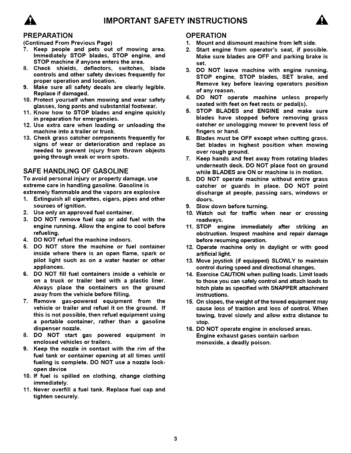
PREPARATION
(Continued From Previous Page)
7. Keep people and pets out of mowing
Immediately STOP blades, STOP engine, and
STOP machine if anyone enters the area.
8. Check shields, deflectors, switches, blade
controls and other safety devices frequently for
proper operation and location.
9. Make sure all safety decals are clearly legible.
Replace if damaged.
10. Protect yourself when mowing and wear safety
glasses, long pants and substantial footwear.
11. Know how to STOP blades and engine quickly
in preparation for emergencies.
12. Use extra care when loading or unloading the
machine into a trailer or truck.
13. Check grass catcher components frequently for
signs of wear or deterioration and replace as
needed to prevent injury from thrown objects
going through weak or worn spots.
area.
SAFE HANDLING OF GASOLINE
To avoid personal injury or property damage, use
extreme care in handling gasoline. Gasoline is
extremely flammable and the vapors are explosive
1. Extinguish all cigarettes, cigars, pipes and other
sources of ignition.
2. Use only an approved fuel container.
3. DO NOT remove fuel cap or add fuel with the
engine running. Allow the engine to cool before
refueling.
4. DO NOT refuel the machine indoors.
5. DO NOT store the machine or fuel container
inside where there is an open flame, spark or
pilot light such as on a water heater or other
appliances.
6. DO NOT fill fuel containers inside a vehicle or
on a truck or trailer bed with a plastic liner.
Always place the containers on the ground
away from the vehicle before filling.
7. Remove gas-powered equipment from the
vehicle or trailer and refuel it on the ground. If
this is not possible, then refuel equipment using
a portable container, rather than a gasoline
dispenser nozzle.
8. DO NOT start gas powered equipment in
enclosed vehicles or trailers.
9. Keep the nozzle in contact with the rim of the
fuel tank or container opening at all times until
fueling is complete. DO NOT use a nozzle lock-
open device
10. If fuel is spilled on clothing, change clothing
immediately.
11. Never overfill a fuel tank. Replace fuel cap and
tighten securely.
OPERATION
1. Mount and dismount machine from left side.
2. Start engine from operator's seat, if possible.
Make sure blades are OFF and parking brake is
set.
3. DO NOT leave machine with engine running.
STOP engine, STOP blades, SET brake, and
Remove key before leaving operators position
of any reason.
4. DO NOT operate machine unless properly
seated with feet on feet rests or pedal(s).
5. STOP BLADES and ENGINE and make sure
blades have stopped before removing grass
catcher or unclogging mower to prevent loss of
fingers or hand.
6. Blades must be OFF except when cutting grass.
Set blades in highest position when mowing
over rough ground.
7. Keep hands and feet away from rotating blades
underneath deck. DO NOT place foot on ground
while BLADES are ON or machine is in motion.
8. DO NOT operate machine without entire grass
catcher or guards in place. DO NOT point
discharge at people, passing cars, windows or
doors.
9. Slow down before turning.
10. Watch out for traffic when near or crossing
roadways.
11. STOP engine immediately after striking an
obstruction. Inspect machine and repair damage
before resuming operation.
12. Operate machine only in daylight or with good
artificial light.
13. Move joystick (if equipped) SLOWLY to maintain
control during speed and directional changes.
14. Exercise CAUTION when pulling loads. Limit loads
to those you can safely control and attach loads to
hitch plate as specified with SNAPPER attachment
instructions.
15. On slopes, the weight of the towed equipment may
cause loss of traction and loss of control. When
towing, travel slowly and allow extra distance to
stop.
16. DO NOT operate engine in enclosed areas.
Engine exhaust gases contain carbon
monoxide, a deadly poison.

IMPORTANT SAFETY INSTRUCTIONS
MAINTENANCE
1. DO NOT store machine or fuel container inside
where fumes may reach an open flame, spark or
pilot light such as in a water heater, furnace,
clothes dryer or other gas appliance. Allow
engine to cool before storing machine in an
enclosure. Store fuel container out of the reach
of children in a well ventilated, unoccupied
building.
2. Keep engine free of grass, leaves or excess
grease to reduce fire hazard and engine
overheating.
3. When draining fuel tank, drain fuel into an
approved container outdoors and away from
open flame.
4. Check brakes frequently; adjust, repair or
replace as needed.
5. Keep all bolts, nuts and screws properly tight.
Check that all cotter pins are in proper position.
6. Always provide adequate ventilation when
running engine. Exhaust gases contain carbon
monoxide, an odorless and deadly poison.
7. Disconnect negative (black) cable from battery
before performing maintenance or service.
Cranking engine could cause injury.
8. DO NOT work under machine without safety
blocks.
9. Service engine and make adjustments only
when engine is stopped. Remove spark plug
wire(s) from spark plug(s) and secure wire(s)
away from spark plug(s).
10. DO NOT change engine governor speed
settings or overspeed engine.
11. Lubricate machine at intervals specified in
manual to prevent controls from binding.
12. Mower blades are sharp and can cut. Wrap the
blades or wear heavy leather gloves and use
CAUTION when handling them.
13. DO NOT test for spark by grounding spark plug
next to spark plug hole; spark plug could ignite
gas exiting engine.
14. Have machine serviced by an authorized
SNAPPER dealer at least once a year and have
the dealer install any new safety devices.
15. Use only genuine SNAPPER replacement parts
to assure that original standards are
maintained.
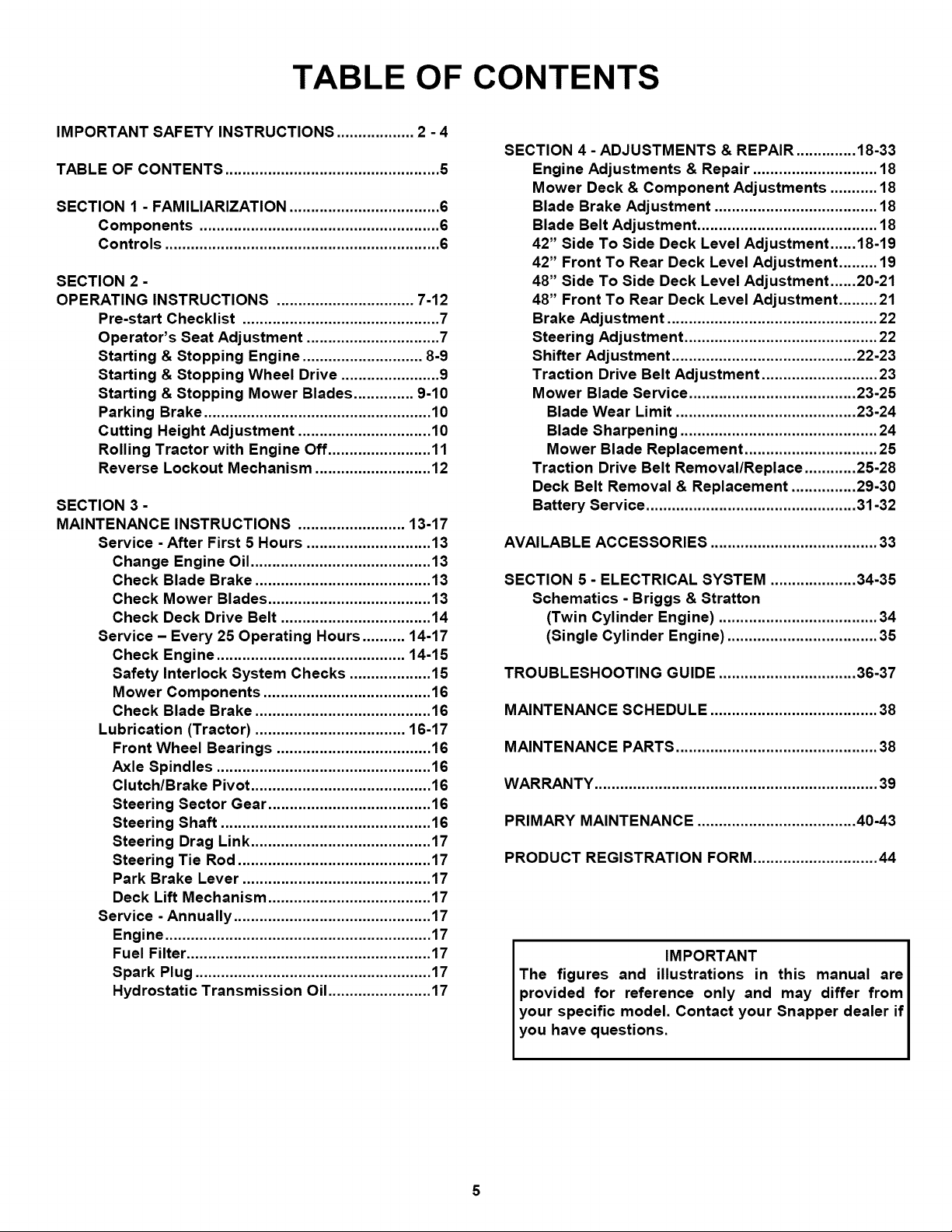
TABLE OF CONTENTS
IMPORTANT SAFETY INSTRUCTIONS .................. 2 - 4
TABLE OF CONTENTS .................................................. 5
SECTION 1 - FAMILIARIZATION ................................... 6
Components ........................................................ 6
Controls ................................................................ 6
SECTION 2 -
OPERATING INSTRUCTIONS ................................ 7-12
Pre-start Checklist .............................................. 7
Operator's Seat Adjustment ............................... 7
Starting & Stopping Engine ............................ 8-9
Starting & Stopping Wheel Drive ....................... 9
Starting & Stopping Mower Blades .............. 9-10
Parking Brake ..................................................... 10
Cutting Height Adjustment ............................... 10
Rolling Tractor with Engine Off ........................ 11
Reverse Lockout Mechanism ........................... 12
SECTION 3-
MAINTENANCE INSTRUCTIONS ......................... 13-17
Service -After First 5 Hours ............................. 13
Change Engine Oil .......................................... 13
Check Blade Brake ......................................... 13
Check Mower Blades ...................................... 13
Check Deck Drive Belt ................................... 14
Service - Every 25 Operating Hours .......... 14-17
Check Engine ............................................ 14-15
Safety Interlock System Checks ................... 15
Mower Components ....................................... 16
Check Blade Brake ......................................... 16
Lubrication (Tractor) ................................... 16-17
Front Wheel Bearings .................................... 16
Axle Spindles .................................................. 16
Clutch/Brake Pivot .......................................... 16
Steering Sector Gear ...................................... 16
Steering Shaft ................................................. 16
Steering Drag Link .......................................... 17
Steering Tie Rod ............................................. 17
Park Brake Lever ............................................ 17
Deck Lift Mechanism ...................................... 17
Service - Annually .............................................. 17
Engine .............................................................. 17
Fuel Filter ......................................................... 17
Spark Plug ....................................................... 17
Hydrostatic Transmission Oil ........................ 17
SECTION 4- ADJUSTMENTS & REPAIR .............. 18-33
Engine Adjustments & Repair ............................. 18
Mower Deck & Component Adjustments ........... 18
Blade Brake Adjustment ...................................... 18
Blade Belt Adjustment .......................................... 18
42" Side To Side Deck Level Adjustment ...... 18-19
42" Front To Rear Deck Level Adjustment ......... 19
48" Side To Side Deck Level Adjustment ......20-21
48" Front To Rear Deck Level Adjustment ......... 21
Brake Adjustment ................................................. 22
Steering Adjustment ............................................. 22
Shifter Adjustment ........................................... 22-23
Traction Drive Belt Adjustment ........................... 23
Mower Blade Service ....................................... 23-25
Blade Wear Limit .......................................... 23-24
Blade Sharpening .............................................. 24
Mower Blade Replacement ............................... 25
Traction Drive Belt Removal/Replace ............ 25-28
Deck Belt Removal & Replacement ............... 29-30
Battery Service ................................................. 31-32
AVAILABLE ACCESSORIES ....................................... 33
SECTION 5 - ELECTRICAL SYSTEM .................... 34-35
Schematics - Briggs & Stratton
(Twin Cylinder Engine) ..................................... 34
(Single Cylinder Engine) ................................... 35
TROUBLESHOOTING GUIDE ................................ 36-37
MAINTENANCE SCHEDULE ....................................... 38
MAINTENANCE PARTS ............................................... 38
WARRANTY .................................................................. 39
PRIMARY MAINTENANCE ..................................... 40-43
PRODUCT REGISTRATION FORM ............................. 44
IMPORTANT
The figures and illustrations in this manual are
provided for reference only and may differ from
your specific model. Contact your Snapper dealer if
you have questions.
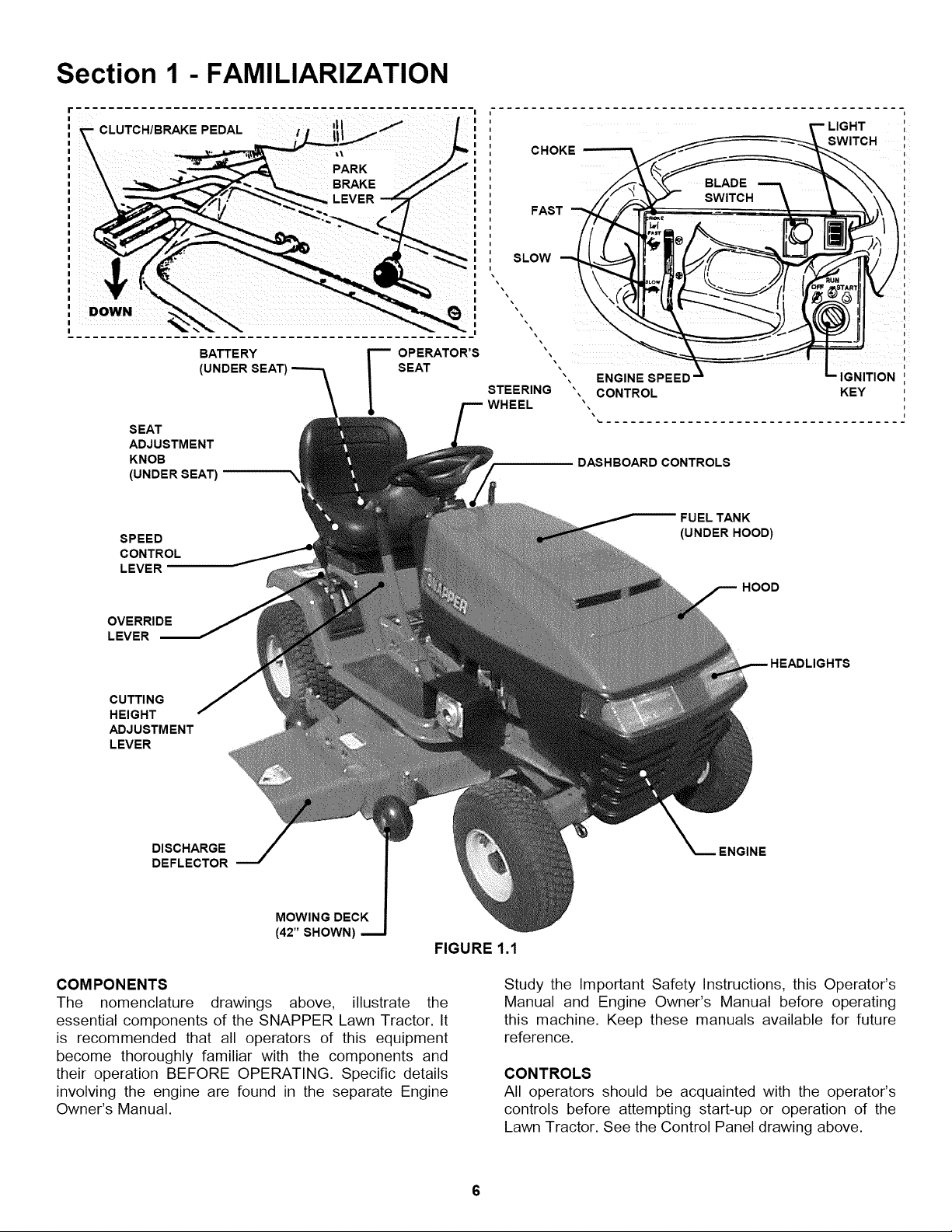
Section 1 - FAMILIARIZATION
CLUTCH/BRAKE PEDAL
DOWN
BATTE RY
(UNDER
SEAT
ADJUSTMENT
KNOB
(UNDER SEAT)
SPEED
CONTROL
LEVER
DASHBOARD CONTROLS
FUEL TANK
(UNDER HOOD)
HOOD
LIGHT
SWITCH
i
I
e
,
, !
-- 1
s
g,,
-- IGNITION
KEY
J
I
OVERRIDE
LEVER
CUTTING
HEIGHT
ADJUSTMENT
LEVER
DISCHARGE
DEFLECTOR
MOWING DECK
(42" SHOWN)
FIGURE 1.1
COMPONENTS
The nomenclature drawings above, illustrate the
essential components of the SNAPPER Lawn Tractor. It
is recommended that all operators of this equipment
become thoroughly familiar with the components and
their operation BEFORE OPERATING. Specific details
involving the engine are found in the separate Engine
Owner's Manual.
HEADLIGHTS
ENGINE
Study the Important Safety Instructions, this Operator's
Manual and Engine Owner's Manual before operating
this machine. Keep these manuals available for future
reference.
CONTROLS
All operators should be acquainted with the operator's
controls before attempting start-up or operation of the
Lawn Tractor. See the Control Panel drawing above.
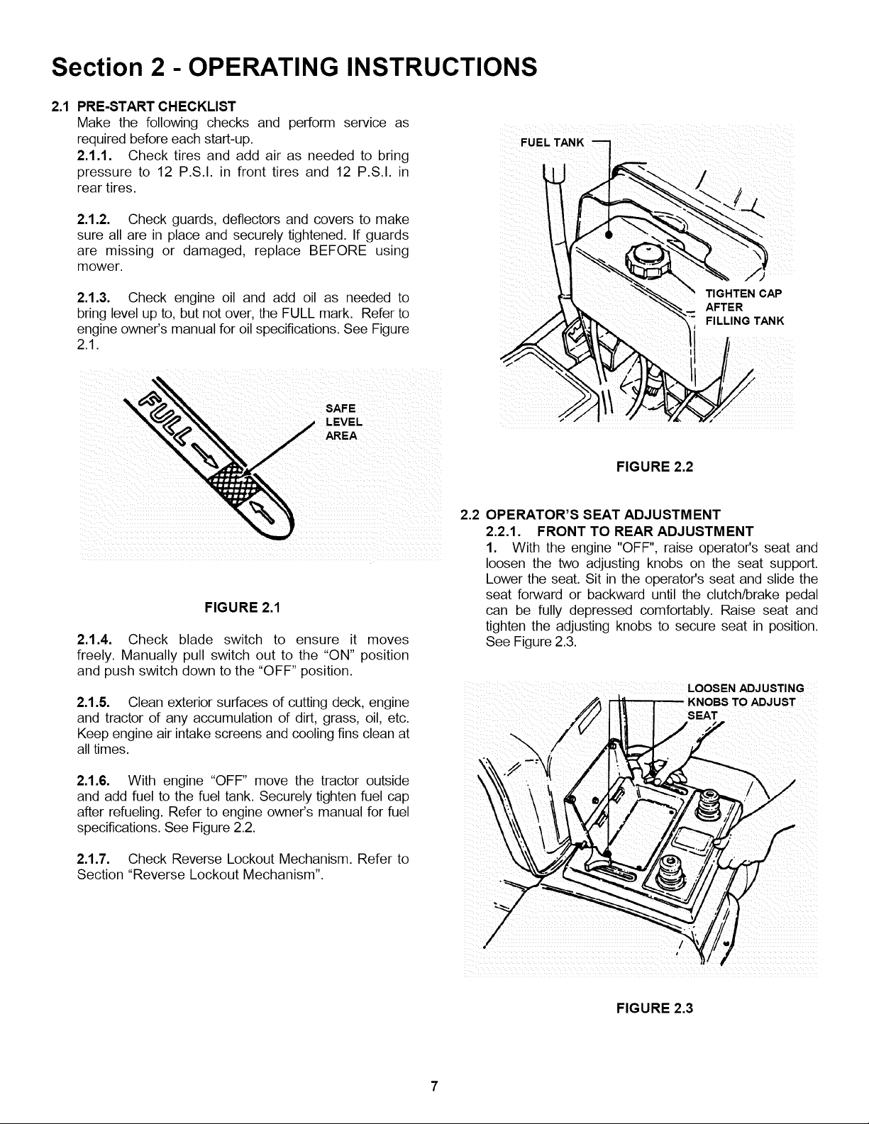
Section 2 - OPERATING INSTRUCTIONS
2.1 PRE-START CHECKLIST
Make the following checks and perform service as
required before each start-up.
2.1.1. Check tires and add air as needed to bring
pressure to 12 P.S.I. in front tires and 12 P.S.I. in
rear tires.
2.1.2. Check guards, deflectors and covers to make
sure all are in place and securely tightened. If guards
are missing or damaged, replace BEFORE using
mower.
FUEL
/
2.1.3. Check engine oil and add oil as needed to
bring level up to, but not over, the FULL mark. Refer to
engine owner's manual for oil specifications. See Figure
2.1.
I
FIGURE 2.1
2.1.4. Check blade switch to ensure it moves
freely. Manually pull switch out to the "ON" position
and push switch down to the "OFF" position.
2.1.5. Clean exterior surfaces of cutting deck, engine
and tractor of any accumulation of dirt, grass, oil, etc.
Keep engine air intake screens and cooling fins clean at
all times.
TIGHTEN CAP
AFTER
FILLING TANK
FIGURE 2.2
2.2 OPERATOR'S SEAT ADJUSTMENT
2.2.1. FRONT TO REAR ADJUSTMENT
1. With the engine "OFF". raise operator's seat and
loosen the two adjusting knobs on the seat support.
Lower the seat. Sit in the operator's seat and slide the
seat forward or backward until the clutch/brake pedal
can be fully depressed comfortably. Raise seat and
tighten the adjusting knobs to secure seat in position.
See Figure 2.3.
i LOOSEN ADJUSTING
ADJUST
SEAT
2.1.6. With engine "OFF" move the tractor outside
and add fuel to the fuel tank. Securely tighten fuel cap
after refueling. Refer to engine owner's manual for fuel
specifications. See Figure 2.2.
2.1.7. Check Reverse Lockout Mechanism. Refer to
Section "Reverse Lockout Mechanism".
FIGURE 2.3

Section 2 - OPERATING INSTRUCTIONS
2.3 STARTING & OPERATION
2.3.1. STARTING ENGINE
1. Take a comfortable position in seat of machine,
look around to make sure that the area you are going to
mow is clear of people, children and pets. Take note of
any stationary obstacles!
NOTE: The interlock system will prevent the engine from
starting if the blade switch is in the "ON" (up) position or if
the clutch/brake pedal is not fully depressed. If the interlock
system ever fails to work, DO NOT OPERATE the tractor
until the interlock has been repaired.
2. Push blade switch down to the "OFF" position. See
Figure 2.4. PUSH BLADE SWITCH "DOWN" TO
START MACHINE
BLADE
5. Choke engine for cold starting by moving engine
speed control to "CHOKE" position. NOTE: Some
models are equipped with a separate choke control,
located on the dash of the tractor. Pull the control
"OUT" to choke position to start a cold engine. Little
or no choking will be needed when restarting a warm
engine. Insert key in switch. Turn key to "START"
position to crank engine and hold until engine starts,
then release key to "RUN" position. See Figure 2.6.
NOTE: DO NOT crank engine for more than five
seconds at a time. This will help prevent the starter from
overheating and/or running down the battery. If cranking
time is more than five seconds, locate and correct cause
of starting problem.
6. After engine starts, release key, move the engine
speed control to "FAST" position and allow engine to
warm up before proceeding. See Figure 2.6.
FAST
FIGURE 2.4 SLOW
\
3. Depress the clutch/brake pedal fully. See Figure 2.5.
4. Move speed control lever to neutral.
ENGINE
NOTE: The seat interlock will shut off the engine if the
operator gets off the seat without setting the parking
SPEED
CONTROL
brake or if the blades are running. If the interlock ever
fails to work, DO NOT OPERATE the tractor until the FIGURE 2.6
interlock has been repaired.
_ CLUTCH!BRAKE
PEDAL
/1 ill
/,,..
DO NOT leave machine with engine running. Stop
engine. Stop blades. Set parking brake. Remove key.
KEY
PUSH PEDAL ALL THE
WAY DOWN TO START
ENGINE
FIGURE 2.5
Section 2 - OPERATING INSTRUCTIONS
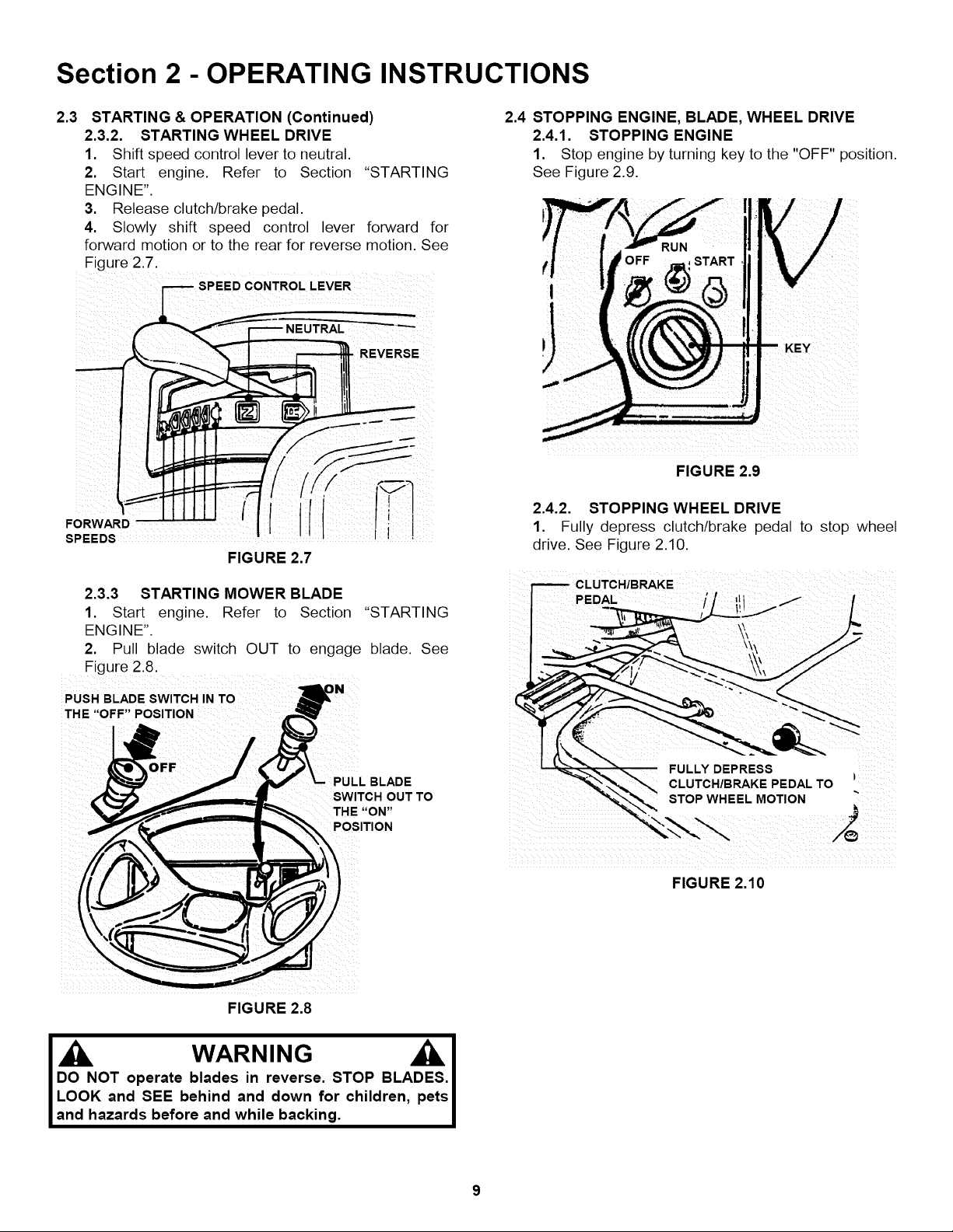
2.3
STARTING & OPERATION (Continued)
2.3.2. STARTING WHEEL DRIVE
1. Shift speed control lever to neutral.
2. Start engine. Refer to Section "STARTING
ENGINE".
3. Release clutch/brake pedal.
4. Slowly shift speed control lever forward for
forward motion or to the rear for reverse motion. See
Figure 2.7.
.... REVERSE
FORWARD !
SPEEDS
FIGURE 2.7
2.4 STOPPING ENGINE, BLADE, WHEEL DRIVE
2.4.1. STOPPING ENGINE
1. Stop engine by turning key to the "OFF" position.
See Figure 2.9.
KEY
FIGURE 2.9
2.4.2. STOPPING WHEEL DRIVE
1. Fully depress clutch/brake pedal to stop wheel
drive. See Figure 2.10.
2.3.3 STARTING MOWER BLADE
1. Start engine. Refer to Section "STARTING
ENGINE".
2. Pull blade switch OUT to engage blade. See
Figure 2.8.
PUSH BLADE SWITCH IN TO
THE ,'OFF" POSITION i
SWITCH OUT TO
THE "ON"
POSITION
FIGURE 2.8
FULLY DEPRESS
STOP WHEEL MOTION
2
FIGURE 2.10
I WARNING
DO NOT operate blades in reverse. STOP BLADES.
LOOK and SEE behind and down for children, pets
and hazards before and while backing.
Section 2 - OPERATING INSTRUCTIONS
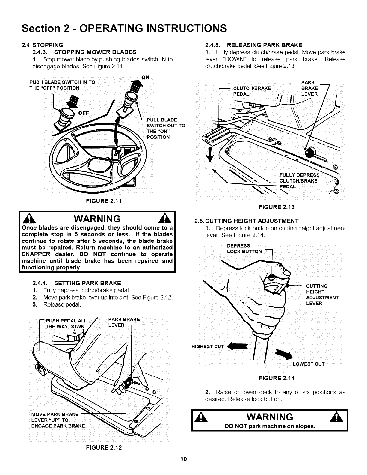
2.4 STOPPING
2.4.3. STOPPING MOWER BLADES
1. Stop mower blade by pushing blades switch IN to
disengage blades. See Figure 2.11.
...... ON
PUSH BLADE SWITCH IN TO
THE "OFF" POSITION
d
,PULL BLADE
SWITCH OUT TO
POSITION
FIGURE 2.11
2.4.5. RELEASING PARK BRAKE
1. Fully depress clutch/brake pedal. Move park brake
lever "DOWN" to release park brake. Release
clutch/brake pedal. See Figure 2.13.
PARK
BRAKE
PEDAL -LEVER
THE "ON"
FIGURE 2.13
WARNING
Once blades are disengaged, they should come to a
complete stop in 5 seconds or less. If the blades
continue to rotate after 5 seconds, the blade brake
must be repaired. Return machine to an authorized
SNAPPER dealer. DO NOT continue to operate
machine until blade brake has been repaired and
functioning properly.
2.4.4. SETTING PARK BRAKE
1. Fully depress clutch/brake pedal.
2. Move park brake lever up into slot. See Figure 2.12.
3. Release pedal.
PEDAL ALL i BRAKE
THE WAY DOWN
i ,
2.5. CUTTING HEIGHT ADJUSTMENT
1. Depress lock button on cutting height adjustment
lever. See Figure 2.14.
DEPRESS
LOCK BUTTON
LOWEST CUT
FIGURE 2,14
2. Raise or lower deck to any of six positions as
desired. Release lock button.
MOVE PARK BRAKE
LEVER "UP" TO
DO NOT park machine on slopes.
FIGURE 2.12
10
Section 2 - OPERATING INSTRUCTIONS
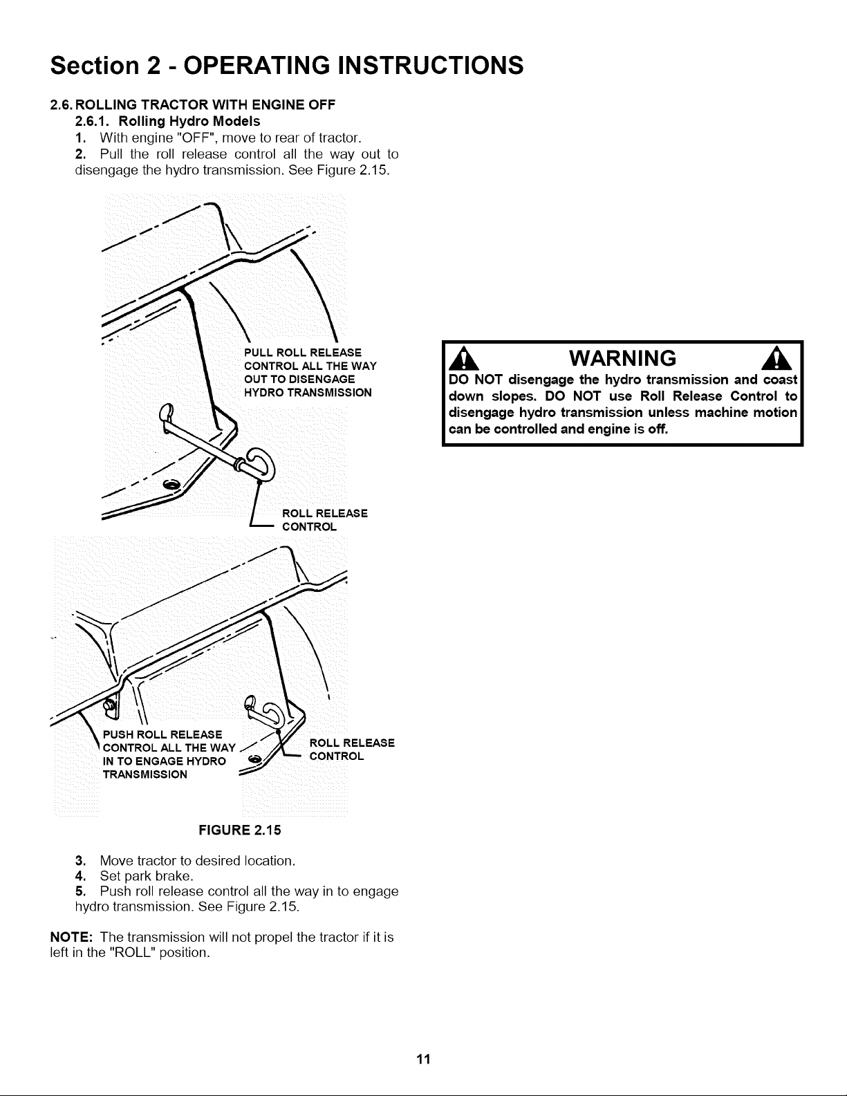
2.6. ROLLING TRACTOR WITH ENGINE OFF
2.6.1. Rolling Hydro Models
1. With engine "OFF", move to rear of tractor.
2. Pull the roll release control all the way out to
disengage the hydro transmission. See Figure 2.15.
PULL ROLL RELEASE
CONTROL ALL THE WAY
OUT TO DISENGAGE
HYDRO TRANSMISSION
DO NOT disengage the hydro transmission and coast
down slopes. DO NOT use Roll Release Control to
disengage hydro transmission unless machine motion
can be controlled and engine is off.
ROLL RELEASE
CONTROL
,_ _i _iI
i PUSH ROLL RELEASE ....
CONTROL ALL THE WAY Z ROLL RELEASE
IN TO ENGAGE HYDRO
TRANSMISSION
FIGURE 2.15
3. Move tractor to desired location.
4. Set park brake.
5. Push roll release control all the way in to engage
hydro transmission. See Figure 2.15.
NOTE: The transmission will not propel the tractor if it is
left in the "ROLL" position.
11
Section 2 - OPERATING INSTRUCTIONS
2.7. REVERSE LOCKOUT MECHANISM
Data indicates that tragic back-over accidents occur
each year. These accidents usually involve unsupervised
children. Many times these children have been given
rides on the machine and have been trained to view this
potentially dangerous piece of machinery as fun rather
than being taught how to avoid danger.
This riding mower has a Reverse Lockout Mechanism.
This mechanism prevents the mower from being shifted
into reverse with the blades running. To shift into reverse
you must first stop the blades and then shift to reverse. It
is our recommendation that this mechanism remain
functional and the operator of this equipment develop the
habit of never backing up with the blades running. As the
Safety Instructions Indicate, DO NOT operate blades in
reverse. STOP BLADES, LOOK AND SEE BEHIND
AND DOWN for children, pets and hazards before
and while backing.
We realize that this could cause a change to your
previous mowing method but we encourage you to adjust
to this new system. Do not defeat the Reverse Lockout
Mechanism.
If you operate your mower near roadways or use
attachments that require quicker shifting to reverse,
there is an override lever provided. This lever can be
pushed and held before engaging the blades and will
allow reverse operation until the blade switch is pushed
in to the "OFF" position, at which time the system will
return to its Reverse Lockout mode. This feature should
never be selected unless you are absolutely sure that no
children or others are present in the mowing area and
that all children are away and supervised by a
responsible adult.
2.7.1.
Reverse Lockout Mechanism Override
1.
Stop machine. Stop blades.
2.
Depress and hold Override Lever.
3.
Pull blade switch "OUT" to engage blade.
4.
Release Override Lever
I , IL. WARNING
LOOK and SEE behind and down for children, pets
and hazards before and while backing.
IMPORTANT! DO NOT use the Reverse Lockout
Mechanism Override as the normal operating mode. To
return to the Reverse Lockout Mechanism mode,
disengage (STOP) blades by pushing blade switch in to
the "OFF" position. The Override will reset to Reverse
Lockout.
2.7.2. Check the Reverse Lockout Mechanism
Before each use, check the Reverse Lockout
Mechanism for proper function. The following
procedure requires the operation of the engine and
blades. Before proceeding, Read, Understand, and
Follow all Safety Instructions and Warnings in this
manual and on the machine.
1. Complete Pre-Start Checklist.
2. Move machine to clear open area. DO NOT
allow children or others in area.
3. Start engine.
4. Pull blade switch "OUT" to engage blades.
5. Reverse Lockout Mechanism must prevent
speed control lever from going into reverse.
WARNING
DO NOT operate machine if Reverse Lockout
Mechanism is not functioning properly. Contact your
SNAPPER dealer immediately for assistance.
®
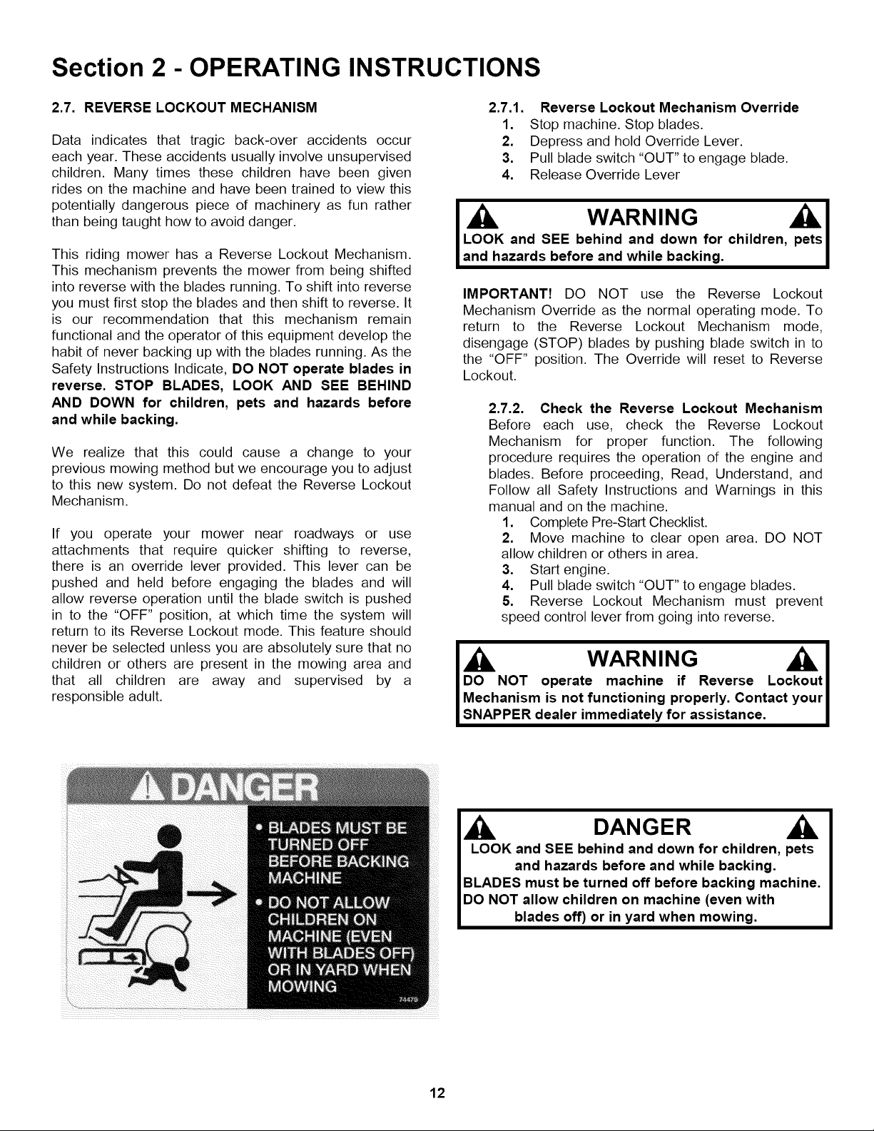
DANGER
LOOK and SEE behind and down for children, pets
and hazards before and while backing.
BLADES must be turned off before backing machine.
DO NOT allow children on machine (even with
blades off) or in yard when mowing.
12
Section 3- MAINTENANCE
3.1 INTRODUCTION
To retain the quality of the Tractor, use genuine
SNAPPER replacement parts only. Contact a local
SNAPPER dealer for parts and service assistance. For
the correct part or information for a particular Tractor,
always mention the model and serial number. SNAPPER
recommends returning the Tractor to an authorized
SNAPPER dealer annually for inspection and addition
of any new devices, which might upgrade the safety of
the Tractor. For the nearest SNAPPER dealer in your
area, check the yellow pages under the heading LAWN
MOWERS. For engine parts and service, look for the
engine manufacturer's dealers under the heading,
ENGINES - gasoline.
3.2 SERVICE - AFTER FIRST 5 HOURS
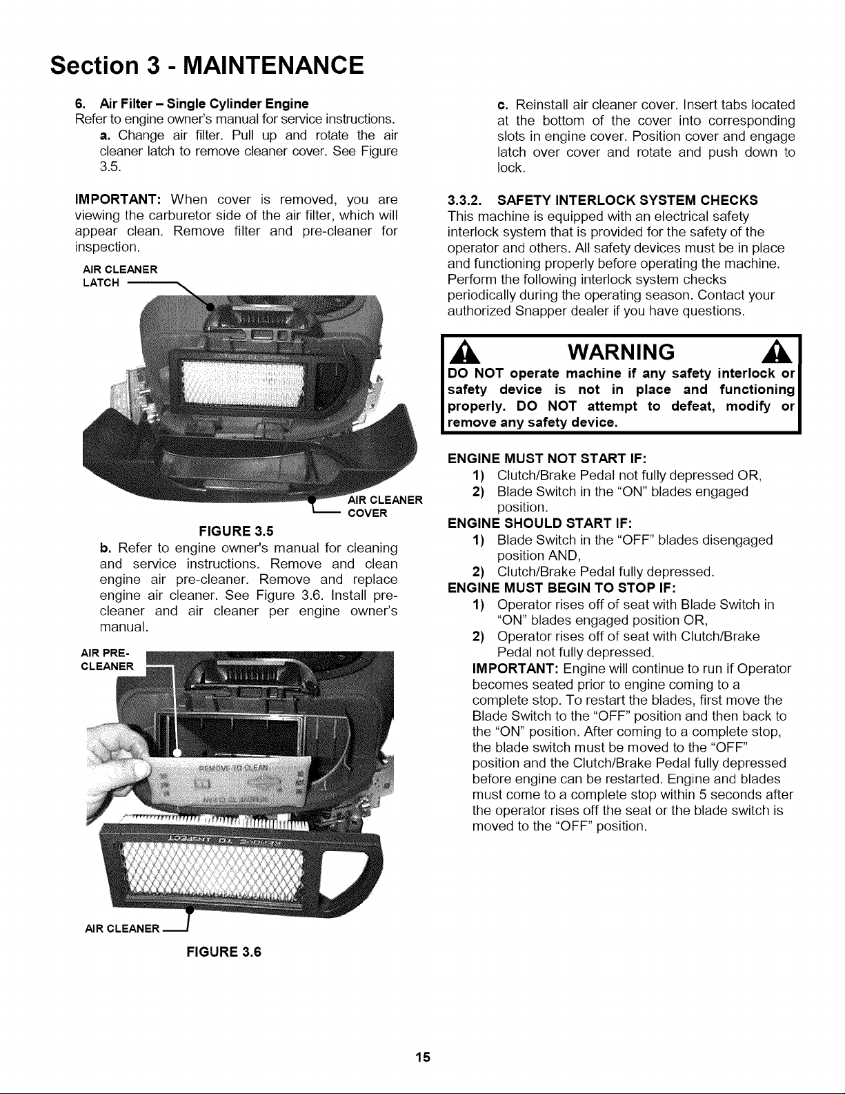
4. Check blade for straightness. Refer to Section
"ADJUSTING MOWER BLADE".
5. Check torque of blade mounting bolts. Torque to:
42" deck - 30 to 40 ft Ibs. See Figure 3.2.
48" deck - 70 to 80 ft lbs.
WARNING
DO NOT attempt any adjust_'nents,maintenance or service
with the engine or blades running. STOP blades. STOP
engine. Set brake. Remove key. Remove spark plug wire
from spark plug and secure wire away from spark plug.
Engine and components can be extremely hot. Avoid bums
byallowing engine and componentssufficienttime to cool.
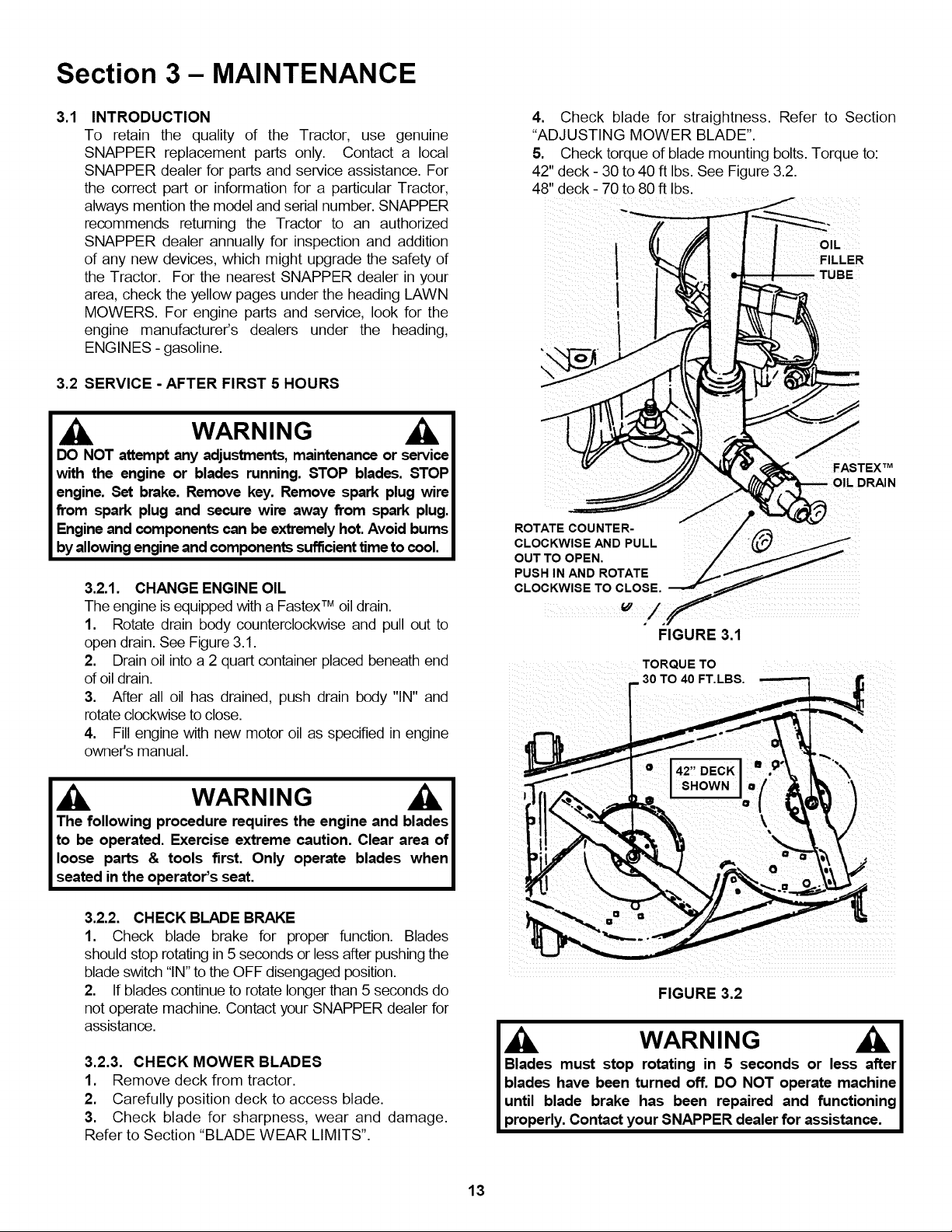
3.2.1. CHANGE ENGINE OIL
The engine is equippedwith a FastexTM oil drain.
1. Rotate drain body counterclockwise and pull out to
open drain. See Figure 3.1.
2. Drain oil into a 2 quart container placed beneath end
of oil drain.
3.
After all oil has drained, push drain body "IN" and
rotate clockwise to close.
4. Fill engine with new motor oil as specified in engine io
CLOCKWISE AND PULL
ROTATECOUNTER
OUT TO OPEN.
PUSH IN AND ROTATE
CLOCKWISE TO CLOSE.
I
OIL
FILLER
FASTEX TM
:)RAIN
FIGURE 3.1
TORQUETO
30 TO 40 FT.LBS. _
owner's manual. • o "'-\
I SHOWN o
,q ,,Y
1. Check blade brake for proper function. Blades
should stop rotating in 5 seconds or less after pushing the
blade switch "IN" to the OFF disengaged position.
2. If blades continue to rotate longer than 5 seconds do
not operate machine. Contact your SNAPPER dealer for
assistance.
3.2.3. CHECK MOWER BLADES
1. Remove deck from tractor.
2. Carefully position deck to access blade.
3. Check blade for sharpness, wear and damage.
Refer to Section "BLADE WEAR LIMITS".
Blades must stop rotating in 5 seconds or less after I
blades have been turned off. DO NOT operate machine I
until blade brake has been repaired and functioning I
properly. Contact your SNAPPER dealer for assistance. I
13
FIGURE 3.2

Section 3 - MAINTENANCE
WARNING
DO NOT attempt any adjustments, maintenance,
service or repairs with the engine running. Stop
engine. Stop blade. Engage parking brake. Remove
key. Remove spark plug wire from spark plug and
secure away from plug. Engine and components are
HOT. Avoid serious burns, allow all parts to cool
before working on machine.
3.2.4. CHECK DECK DRIVE BELT
1. The idler and spring provide proper belt tension and
require no adjustment. If belt is frayed, slit, severed or
belt strands exposed, replace belt before operating
mower.
SERVICE - EVERY 25 OPERATING HOURS
3.3.1. CHECK ENGINE
1. Engine Cooling System
The engine cooling system consists of an engine
shroud and engine fins. These should be kept clean
and free of debris as needed or cleaned.
2. Engine Oil
Change engine oil. See Section on CHANGE ENGINE
OIL. Refer to engine owner's manual for oil
specifications.
3. Oil Filter
Change engine oil filter. Refer to engine owner's
manual for filter specifications.
4. Fuel Filter
Refer to engine owner's manual for service
instructions.
5. Air Filter- Twin Cylinder Engine
Refer to engine owner's manual for service
instructions.
a. Change air filter. Remove bolts that secure air
cleaner cover to the engine. See Figure 3.3.
NOTE: YELLOW TABS MUST BE
COMPLETELY INSERTED INTO SLOTS
FIGURE 3.3
AIR PRE-
CLEANER
MR CLEANER
IMPORTANT: When cover is removed, you are
viewing the carburetor side of the air filter, which will
appear clean. Remove filter and pre-cleaner for
inspection.
b. Refer to engine owner's manual for cleaning
and service instructions. Remove and clean
engine air pre-cleaner. Remove and replace
engine air cleaner. See Figure 3.4. Install pre-
cleaner and air cleaner per engine owner's
manual.
FIGURE 3.4
c. Reinstall air cleaner cover. Insert tabs located
on the engine cover into corresponding slots in
air cleaner cover. IMPORTANT: The yellow tabs
must be completely inserted into air cleaner
cover or the compartment will not be completely
sealed to prevent debris from entering into the
carburetor.
d. Reinstall bolts that secure air cleaner cover to
the engine. Tighten securely.
14
Section 3 - MAINTENANCE
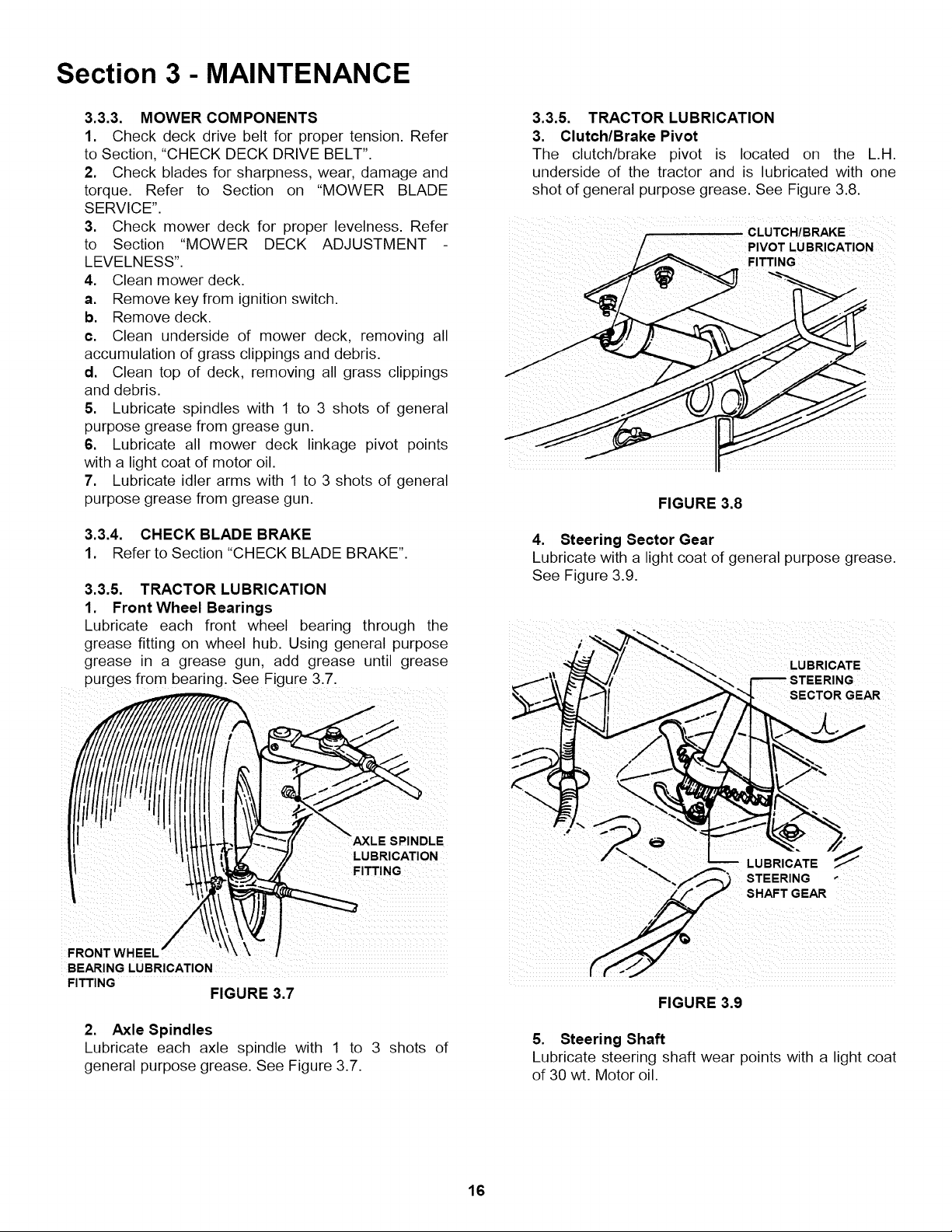
6. Air Filter- Single Cylinder Engine
Refer to engine owner's manual for service instructions.
a. Change air filter. Pull up and rotate the air
cleaner latch to remove cleaner cover. See Figure
3.5.
IMPORTANT: When cover is removed, you are
viewing the carburetor side of the air filter, which will
appear clean. Remove filter and pre-cleaner for
inspection.
AIR CLEANER
LATCH
AIR CLEANER
COVER
FIGURE 3.5
b. Refer to engine owner's manual for cleaning
and service instructions. Remove and clean
engine air pre-cleaner. Remove and replace
engine air cleaner. See Figure 3.6. Install pre-
cleaner and air cleaner per engine owner's
manual.
AIR PRE-
CLEANER
c. Reinstall air cleaner cover. Insert tabs located
at the bottom of the cover into corresponding
slots in engine cover. Position cover and engage
latch over cover and rotate and push down to
lock.
3.3.2. SAFETY INTERLOCK SYSTEM CHECKS
This machine is equipped with an electrical safety
interlock system that is provided for the safety of the
operator and others. All safety devices must be in place
and functioning properly before operating the machine.
Perform the following interlock system checks
periodically during the operating season. Contact your
authorized Snapper dealer if you have questions.
WARNING
DO NOT operate machine if any safety interlock or
safety device is not in place and functioning
properly. DO NOT attempt to defeat, modify or
remove any safety device.
ENGINE MUST NOT START IF:
1) Clutch/Brake Pedal not fully depressed OR,
2) Blade Switch in the "ON" blades engaged
position.
ENGINE SHOULD START IF:
1) Blade Switch in the "OFF" blades disengaged
position AND,
2) Clutch/Brake Pedal fully depressed.
ENGINE MUST BEGIN TO STOP IF:
1) Operator rises off of seat with Blade Switch in
"ON" blades engaged position OR,
2} Operator rises off of seat with Clutch/Brake
Pedal not fully depressed.
IMPORTANT: Engine will continue to run if Operator
becomes seated prior to engine coming to a
complete stop. To restart the blades, first move the
Blade Switch to the "OFF" position and then back to
the "ON" position. After coming to a complete stop,
the blade switch must be moved to the "OFF"
position and the Clutch/Brake Pedal fully depressed
before engine can be restarted. Engine and blades
must come to a complete stop within 5 seconds after
the operator rises off the seat or the blade switch is
moved to the "OFF" position.
mR CLEANER
FIGURE 3.6
15
Section 3 - MAINTENANCE
3.3.3. MOWER COMPONENTS
1. Check deck drive belt for proper tension. Refer
to Section, "CHECK DECK DRIVE BELT".
2. Check blades for sharpness, wear, damage and
torque. Refer to Section on "MOWER BLADE
SERVICE".
3. Check mower deck for proper levelness. Refer
to Section "MOWER DECK ADJUSTMENT
LEVELNESS".
4. Clean mower deck.
a. Remove key from ignition switch.
b. Remove deck.
c. Clean underside of mower deck, removing all
accumulation of grass clippings and debris.
d. Clean top of deck, removing all grass clippings
and debris.
5. Lubricate spindles with 1 to 3 shots of general
purpose grease from grease gun.
6. Lubricate all mower deck linkage pivot points
with a light coat of motor oil.
7. Lubricate idler arms with 1 to 3 shots of general
purpose grease from grease gun.
3.3.4. CHECK BLADE BRAKE
1. Refer to Section "CHECK BLADE BRAKE".
3.3.5. TRACTOR LUBRICATION
1. Front Wheel Bearings
Lubricate each front wheel bearing through the
grease fitting on wheel hub. Using general purpose
grease in a grease gun, add grease until grease
purges from bearing. See Figure 3.7.
i
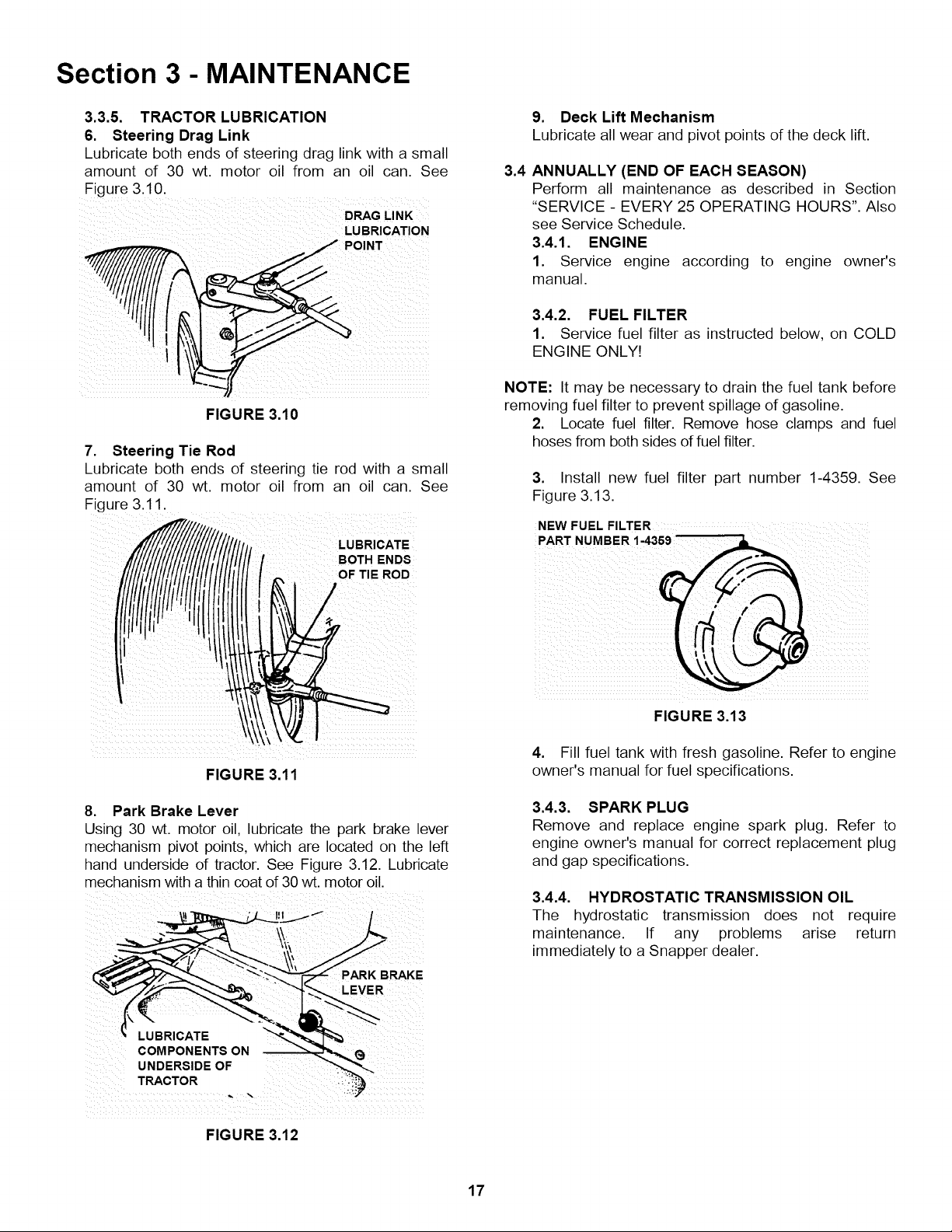
3.3.5. TRACTOR LUBRICATION
3. Clutch/Brake Pivot
The clutch/brake pivot is located on the L.H.
underside of the tractor and is lubricated with one
shot of general purpose grease. See Figure 3.8.
PIVOT LUBRICATION
FIGURE 3.8
4. Steering Sector Gear
Lubricate with a light coat of general purpose grease.
See Figure 3.9.
LUBRICATE
• SECTOR GEAR
LUBRICATION
FITTING
ii!ii ii! ¸¸
FRONT WHEEL"
BEARING LUBRICATION
FITTING
2. Axle Spindles
Lubricate each axle spindle with 1 to 3 shots of
general purpose grease. See Figure 3.7.
FIGURE 3,7
SPINDLE
__ LUBRICATE _'
" SHAFT GEAR
STEERING "
FIGURE 3.9
5. Steering Shaft
Lubricate steering shaft wear points with a light coat
of 30 wt. Motor oil.
16
Section 3 - MAINTENANCE
3.3.5. TRACTOR LUBRICATION
6. Steering Drag Link
Lubricate both ends of steering drag link with a small
amount of 30 wt. motor oil from an oil can. See
Figure 3.10.
DRAG LINK
_J POINT
iiiii_ _i I _i_ _ _i_ii_ii_i_i_!iii__ _i_ii_?_ilili
FIGURE 3.10
7. Steering Tie Rod
Lubricate both ends of steering tie rod with a small
amount of 30 wt. motor oil from an oil can. See
Figure 3.11.
LUBRICATE
BOTH ENDS
OF TIE ROD
r
9. Deck Lift Mechanism
Lubricate all wear and pivot points of the deck lift.
3.4
ANNUALLY (END OF EACH SEASON)
Perform all maintenance as described in Section
"SERVICE - EVERY 25 OPERATING HOURS". Also
see Service Schedule.
3.4.1. ENGINE
1. Service engine according to engine owner's
manual.
3.4.2. FUEL FILTER
1. Service fuel filter as instructed below, on COLD
ENGINE ONLY!
NOTE: It may be necessary to drain the fuel tank before
removing fuel filter to prevent spillage of gasoline.
2. Locate fuel filter. Remove hose clamps and fuel
hoses from both sides of fuel filter.
3. Install new fuel filter part number 1-4359. See
Figure 3.13.
FIGURE 3.11
8. Park Brake Lever
Using 30 wt. motor oil, lubricate the park brake lever
mechanism pivot points, which are located on the left
hand underside of tractor. See Figure 3.12. Lubricate
mechanism with a thin coat of 30 wt. motor oil.
PARK BRAKE
LEVER
LUBRICATE
COMPONENTS ON
TRACTO R
FIGURE 3.12
FIGURE 3.13
4. Fill fuel tank with fresh gasoline. Refer to engine
owner's manual for fuel specifications.
3.4.3. SPARK PLUG
Remove and replace engine spark plug. Refer to
engine owner's manual for correct replacement plug
and gap specifications.
3.4.4. HYDROSTATIC TRANSMISSION OIL
The hydrostatic transmission does not require
maintenance. If any problems arise return
immediately to a Snapper dealer.
17
Section 4 - ADJUSTMENT & REPAIR
WARNING
DO NOT attempt any adjustments, maintenance or
service with the engine or blades running. STOP
blades. STOP engine. Set brake. Remove key.
Remove spark plug wire from spark plug and secure
wire away from spark plug. Engine and components
can be extremely hot. Avoid burns by allowing engine
and components sufficient time to cool.
4.1 ENGINE ADJUSTMENTS & REPAIR
Refer to the engine owner's manual for those
adjustments and/or repairs that can be made by the
owner.
4.2 MOWER DECK & COMPONENT ADJUSTMENTS
The following mower deck and component adjustments
and repairs can be made by the owner. However, if there
is difficulty in achieving these adjustments and repairs, it
is recommended that these repairs be made by an
authorized SNAPPER dealer.
ADJUSTING
NUT (3)
FIGURE 4.1
.012" TO .014" I
• FEELER GAUGE I
I
I Blades must stop rotating in 5 seconds or less after I
blades have been turned off. DO NOT operate I
machine until blade brake has been repaired and I
functioning properly. Contact your SNAPPER dealer I
for assistance. I
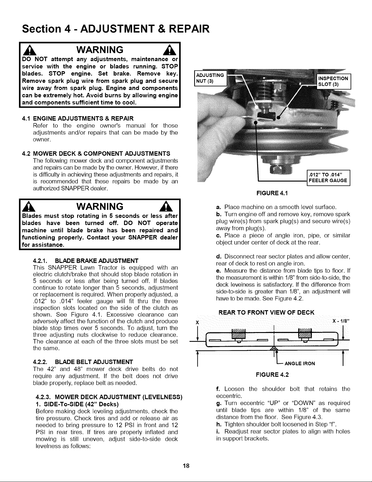
4.2.1. BLADE BRAKE ADJUSTMENT
This SNAPPER Lawn Tractor is equipped with an
electric clutch/brake that should stop blade rotation in
5 seconds or less after being turned off. If blades
continue to rotate longer than 5 seconds, adjustment
or replacement is required. When properly adjusted, a
.012" to .014" feeler gauge will fit thru the three
inspection slots located on the side of the clutch as
shown. See Figure 4.1. Excessive clearance can
adversely affect the function of the clutch and produce
blade stop times over 5 seconds. To adjust, turn the
three adjusting nuts clockwise to reduce clearance.
The clearance at each of the three slots must be set
the same.
4.2.2. BLADE BELT ADJUSTMENT
The 42" and 48" mower deck drive belts do not
require any adjustment. If the belt does not drive
blade properly, replace belt as needed.
4.2.3. MOWER DECK ADJUSTMENT (LEVELNESS)
1. SIDE-To-SIDE (42" Decks)
Before making deck leveling adjustments, check the
tire pressure. Check tires and add or release air as
needed to bring pressure to 12 PSI in front and 12
PSI in rear tires. If tires are properly inflated and
mowing is still uneven, adjust side-to-side deck
levelness as follows:
a. Place machine on a smooth level surface.
b. Turn engine off and remove key, remove spark
plug wire(s) from spark plug(s) and secure wire(s)
away from plug(s).
c. Place a piece of angle iron, pipe, or similar
object under center of deck at the rear.
d. Disconnect rear sector plates and allow center,
rear of deck to rest on angle iron.
e. Measure the distance from blade tips to floor. If
the measurement is within 1/8" from side-to-side, the
deck levelness is satisfactory. If the difference from
side-to-side is greater than 1/8", an adjustment will
have to be made. See Figure 4.2.
REAR TO FRONT VIEW OF DECK
ANGLE IRON
FIGURE 4.2
f. Loosen the shoulder bolt that retains the
eccentric.
g. Turn eccentric "UP" or "DOWN" as required
until blade tips are within 1/8" of the same
distance from the floor. See Figure 4.3.
h. Tighten shoulder bolt loosened in Step "f".
i. Readjust rear sector plates to align with holes
in support brackets.
18
Section 4- ADJUSTMENT & REPAIR
WARNING
DO NOT attempt any adjustments, maintenance or
service with the engine or blades running. STOP
blades. STOP engine. Set brake. Remove key.
Remove spark plug wire from spark plug and secure
wire away from spark plug. Engine and components
can be extremely hot. Avoid burns by allowing engine
and components sufficient time to cool.
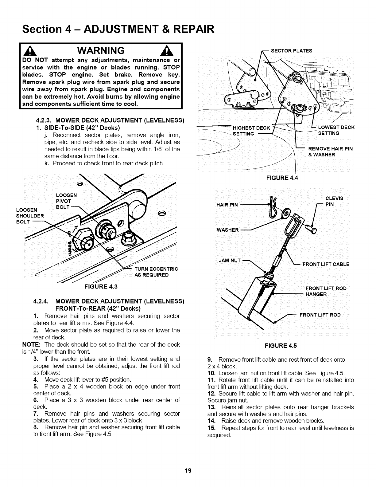
4.2.3. MOWER DECK ADJUSTMENT (LEVELNESS)
1. SIDE-To-SIDE (42" Decks)
j. Reconnect sector plates, remove angle iron,
pipe, etc. and recheck side to side level. Adjust as
needed to result in blade tips being within 118"of the
same distance from the floor.
k. Proceed to check front to rear deck pitch.
SECTOR PLATES
!
• "\
& WASHER
FIGURE 4.4
CLEVIS
HAIR PIN
WASHER
- TURN ECCENTRIC
AS REQUIRED
FIGURE 4.3
4.2.4. MOWER DECK ADJUSTMENT (LEVELNESS)
FRONT-To-REAR (42" Decks)
1. Remove hair pins and washers securing sector
plates to rear lift arms. See Figure 4.4.
2. Move sector plate as required to raise or lower the
rear of deck.
NOTE" The deck should be set so that the rear of the deck
is 1/4" lower than the front.
3. If the sector plates are in their lowest setting and
proper level cannot be obtained, adjust the front lift rod
as follows:
4. Move deck liftlever to #5 position.
5. Place a 2 x 4 wooden block on edge under front
center of deck.
6. Place a 3 x 3 wooden block under rear center of
deck.
7. Remove hair pins and washers securing sector
plates. Lower rear of deck onto 3 x 3 block.
8. Remove hair pin and washer securing front lift cable
to front liftarm. See Figure 4.5.
LIFT CABLE
FRONT LIFT ROD
HANGER
FIGURE 4.5
9. Remove front lift cable and rest front of deck onto
2 x 4 block.
10. Loosen jam nut on front lift cable. See Figure 4.5.
11. Rotate front lift cable until it can be reinstalled into
front lift arm without liftingdeck.
12. Secure lift cable to lift arm with washer and hair pin.
Secure jam nut.
13. Reinstall sector plates onto rear hanger brackets
and secure with washers and hair pins.
14. Raise deck and remove wooden blocks.
15. Repeat steps for front to rear level until levelness is
acquired.
19
Section 4 - ADJUSTMENT & REPAIR
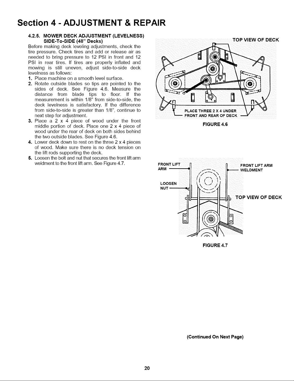
4.2.5. MOWER DECK ADJUSTMENT (LEVELNESS)
SIDE-To-SIDE (48" Decks)
Before making deck leveling adjustments, check the
tire pressure. Check tires and add or release air as
needed to bring pressure to 12 PSI in front and 12
PSI in rear tires. If tires are properly inflated and
mowing is still uneven, adjust side-to-side deck
levelness as follows:
1. Place machine on a smooth level surface.
2. Rotate outside blades so tips are pointed to the
sides of deck. See Figure 4.6. Measure the
distance from blade tips to floor. If the
measurement is within 1/8" from side-to-side, the
deck levelness is satisfactory. If the difference
from side-to-side is greater than 118", continue to
next step for adjustment.
3. Place a 2 x 4 piece of wood under the front
middle portion of deck. Place one 2 x 4 piece of
wood under the rear of deck on both sides behind
the two outside blades. See Figure 4.6.
4. Lower deck down to rest on the three 2 x 4 pieces
of wood. Make sure there is no deck tension on
the lift rods supporting the deck.
5. Loosen the bolt and nut that secures the front lift arm
weldment to the front lift arm. See Figure 4.7.
TOP VIEW OF DECK
t PLACE THREE 2 X4 UNDER
FRONT AND REAR OF DECK
FIGURE 4.6
LL¸ i i LL
FRONT LIFT j] _ FRONT LIFT ARM
ARM ,F _ --,. Itl_ WELDMENT
II ll_", II
NUT _e_ ILOOSEN __
/ "",/
, TOP VIEW OF DECK
FIGURE 4.7
20
(Continued On Next Page)
Section 4 - ADJUSTMENT & REPAIR
WARNING
DO NOT attempt any adjustments, maintenance or
service with the engine or blades running. STOP
blades. STOP engine. Set brake. Remove key.
Remove spark plug wire from spark plug and secure
wire away from spark plug. Engine and components
can be extremely hot. Avoid burns by allowing engine
and components sufficient time to cool.
4.2.5. MOWER DECK ADJUSTMENT (LEVELNESS)
SIDE-To-SIDE (48" Decks)
(Continued From Previous Page)
6. Remove both hair pins and washers from swivel
located on rear lift rods and pull rod out of deck
brackets.
7. Rotate swivels on both sides up or down to
achieve the proper levelness. See Figure 4.8.
8. Reinstall swivel into deck bracket. Reinstall
washers and hair pins.
9. Tighten nut and bolt on front lift arm securely.
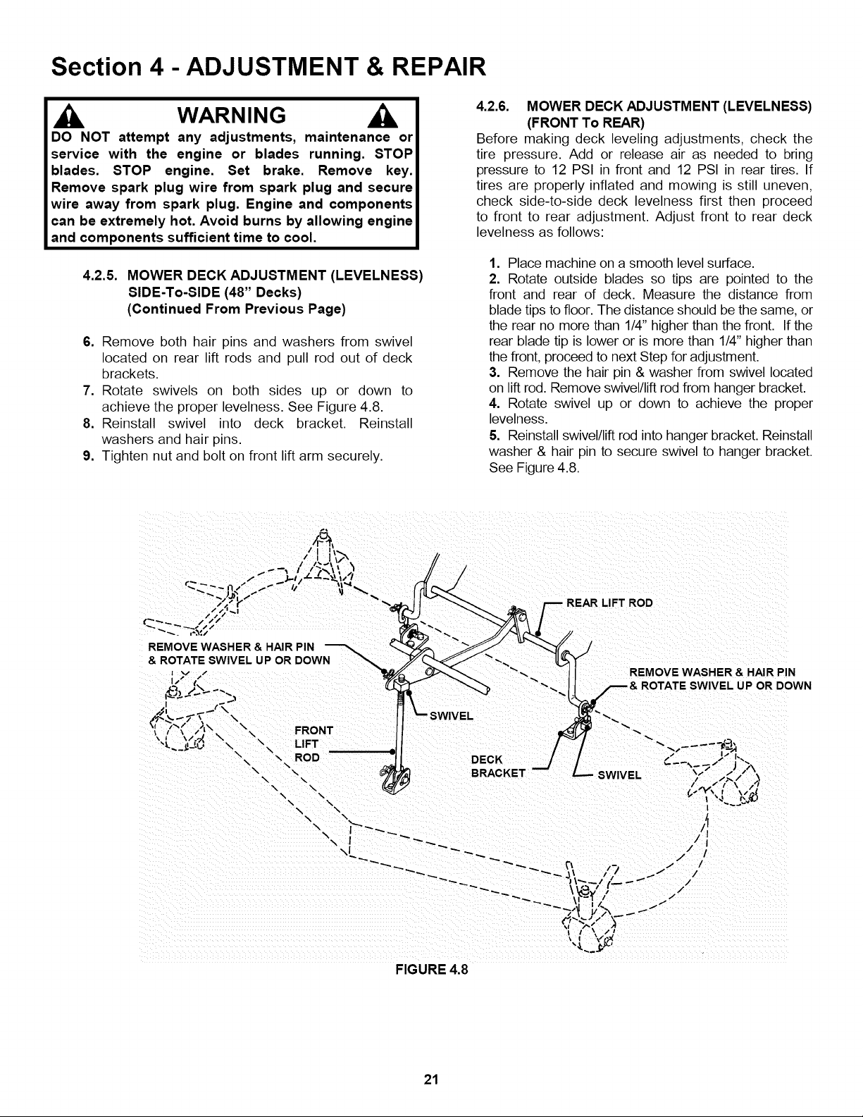
4.2.6. MOWER DECK ADJUSTMENT (LEVELNESS)
(FRONT To REAR)
Before making deck leveling adjustments, check the
tire pressure. Add or release air as needed to bring
pressure to 12 PSI in front and 12 PSI in rear tires. If
tires are properly inflated and mowing is still uneven,
check side-to-side deck levelness first then proceed
to front to rear adjustment. Adjust front to rear deck
levelness as follows:
1. Place machine on a smooth level surface.
2. Rotate outside blades so tips are pointed to the
front and rear of deck. Measure the distance from
blade tips to floor. The distance should be the same, or
the rear no more than 114"higher than the front. If the
rear blade tip is lower or is more than 114"higher than
the front, proceed to next Step for adjustment.
3. Remove the hair pin & washer from swivel located
on lift rod. Remove swivel/lift rod from hanger bracket.
4. Rotate swivel up or down to achieve the proper
levelness.
5. Reinstall swivel/lift rod into hanger bracket. Reinstall
washer & hair pin to secure swivel to hanger bracket.
See Figure 4.8.
REMOVE WASHER & HAIR PIN
& ROTATE SWIVEL UP OR DOWN
I v /
I ,s t(,
JK,
\
\ \ FRONT
-_. \ LIFT
\
\,, \ ROD DECK
"\\ "\\
-_ '%,
\ \
\ \
\ \.
/
REAR LIFT ROD
REMOVE WASHER & HAIR PIN
UP OR DOWN
SWIVEL
FIGURE 4.8
21
Section 4 - ADJUSTMENT & REPAIR
WARNING
DO NOT attempt any adjustments, maintenance or
service with the engine or blades running. STOP
blades. STOP engine. Set brake. Remove key.
Remove spark plug wire from spark plug and secure
wire away from spark plug. Engine and components
can be extremely hot. Avoid burns by allowing engine
and components sufficient time to cool.
4.3 TRACTOR DRIVE COMPONENTS
4.3.1. BRAKE ADJUSTMENT
When adjusted properly, the brake should stop the
tractor in approximately 6 feet or less from top speed.
Drive the machine at maximum forward speed and
apply the brake. If stopping distance is greater than 6
feet, brake adjustment is required.
1. Turn engine "OFF". Remove key.
2. Locate brake adjustment nut underneath the left side
at the rear of tractor. See Figure 4.9.
3. Turn nut 1 turn clockwise to increase braking
action. DO NOT over tighten brake adjustment.
4. Start engine and test brake.
5. Continue adjustment as described above until
proper brake function is achieved.
CLOCKWISE TO DECREASE
BRAKING
., TANK
-----
FIGURE 4.10
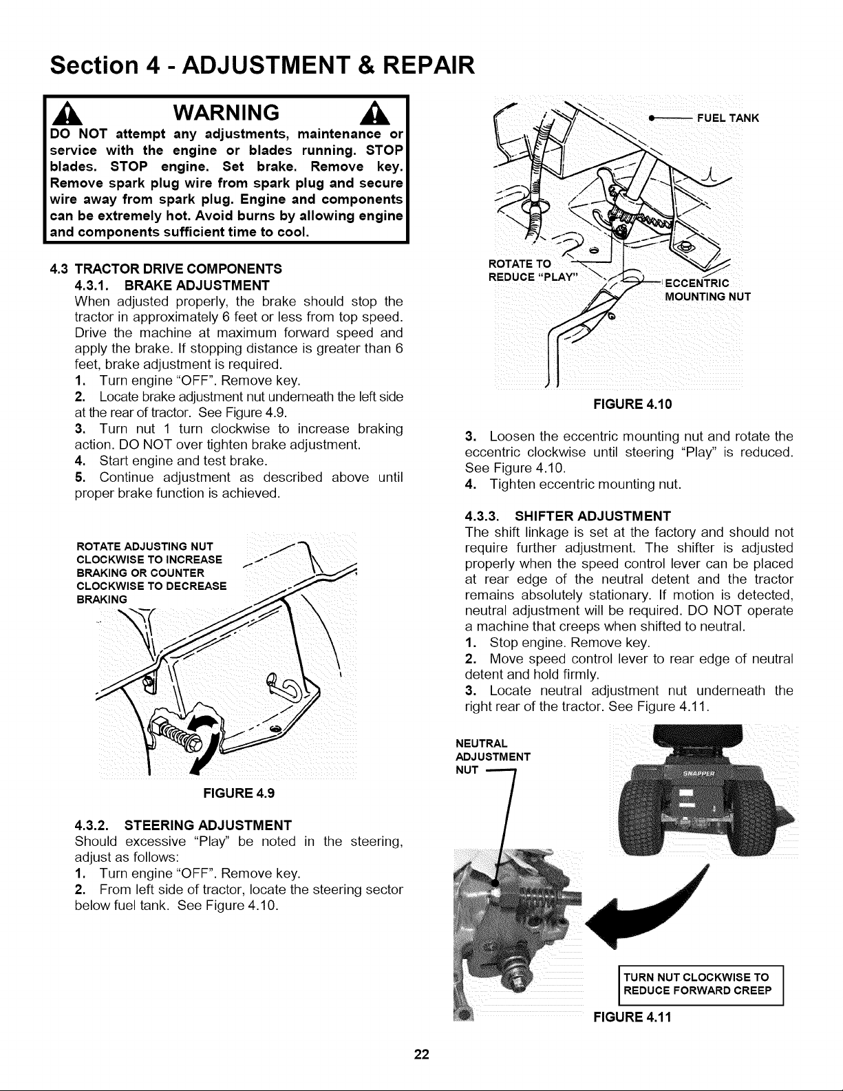
3. Loosen the eccentric mounting nut and rotate the
eccentric clockwise until steering "Play" is reduced.
See Figure 4.10.
4. Tighten eccentric mounting nut.
4.3.3. SHIFTER ADJUSTMENT
The shift linkage is set at the factory and should not
require further adjustment. The shifter is adjusted
properly when the speed control lever can be placed
at rear edge of the neutral detent and the tractor
remains absolutely stationary. If motion is detected.
neutral adjustment will be required. DO NOT operate
a machine that creeps when shifted to neutral.
1. Stop engine. Remove key.
2. Move speed control lever to rear edge of neutral
detent and hold firmly.
3. Locate neutral adjustment nut underneath the
right rear of the tractor. See Figure 4.11.
4.3.2. STEERING ADJUSTMENT
Should excessive "Play" be noted in the steering,
adjust as follows:
1. Turn engine "OFF". Remove key.
2. From left side of tractor, locate the steering sector
below fuel tank. See Figure 4.10.
22
NEUTRAL
ADJ USTM ENT
NUT
TURN NUT CLOCKWISE TO I
REDUCE FORWARD CREEP I
FIGURE 4.11
I
Section 4 - ADJUSTMENT & REPAIR
WARNING
DO NOT attempt any adjustments, maintenance or
service with the engine or blades running. STOP
blades. STOP engine. Set brake. Remove key.
Remove spark plug wire from spark plug and secure
wire away from spark plug. Engine and components
can be extremely hot. Avoid burns by allowing engine
and components sufficient time to cool. Wear heavy
leather gloves when handling or working around
cutting blades. Blades are extremely sharp and can
cause severe injury.
4.3.3. SHIFTER ADJUSTMENT
(Continued from previous page)
4. Turn the neutral adjustment nut 1/4 turn clockwise
to reduce FORWARD creep. Turn the adjustment nut
1/4 turn counter clockwise to reduce Reverse creep.
Only turn the adjustment nut in 1/4 turn increments.
5. Check for creep in neutral. Start engine. Move
speed control lever to rear edge of the neutral detent.
Machine should not move. If further adjustment is
required, stop engine and repeat Step 4.
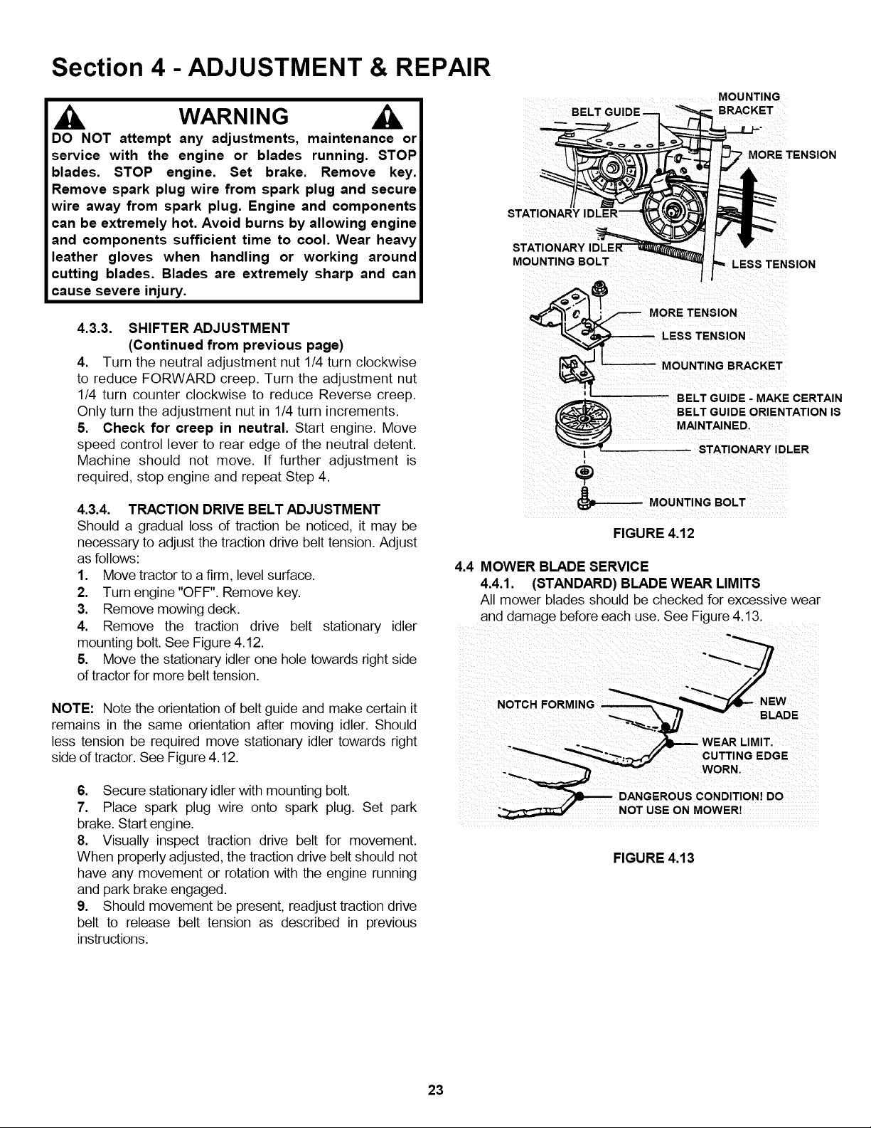
4.3.4. TRACTION DRIVE BELT ADJUSTMENT
Should a gradual loss of traction be noticed, it may be
necessary to adjust the traction drive belt tension. Adjust
as follows:
1. Move tractor to a firm, level surface.
2. Turn engine "OFF". Remove key.
3. Remove mowing deck.
4. Remove the traction drive belt stationary idler
mounting bolt. See Figure 4.12.
5. Move the stationary idler one hole towards right side
of tractor for more belt tension.
4.4 MOWER BLADE SERVICE
MOUNTING
BELT - BRACKET
' MORE TENSION
MOUNTING BOLT _ISION
BELT GUIDE - MAKE CERTAIN
MAINTAINED.
BELT GUIDE ORIENTATION IS
STATIONARY IDLER
®
MOUNTING BOLT
FIGURE 4.12
4.4.1. (STANDARD) BLADE WEAR LIMITS
All mower blades should be checked for excessive wear
and damage before each use. See Figure 4.13.
NOTE: Note the orientation of belt guide and make certain it
remains in the same orientation after moving idler. Should
less tension be required move stationary idler towards right
side of tractor. See Figure 4.12.
6. Secure stationary idler with mounting bolt.
7. Place spark plug wire onto spark plug. Set park
brake. Start engine.
8. Visually inspect traction drive belt for movement.
When properly adjusted, the traction drive belt should not
have any movement or rotation with the engine running
and park brake engaged.
9. Should movement be present, readjust traction drive
belt to release belt tension as described in previous
instructions.
NOTCH FORMING W
,__ _ WEAR LIMIT,
CUTTING EDGE
WORN.
DANG EROUS CONDITION! DO
_;_ NOT USE ON MOWER!
FIGURE 4.13
23
Section 4 - ADJUSTMENT & REPAIR
WARNING
DO NOT attempt any adjustments, maintenance or
service with the engine or blades running. STOP
blades. STOP engine. Set brake. Remove key.
Remove spark plug wire from spark plug and secure
wire away from spark plug. Engine and components
can be extremely hot. Avoid burns by allowing engine
and components sufficient time to cool. Wear heavy
leather gloves when handling or working around
cutting blades. Blades are extremely sharp and can
cause severe injury.
STANDARD BLADE
IGINAL CUTTING EDGE
FIGURE 4.15
/
/
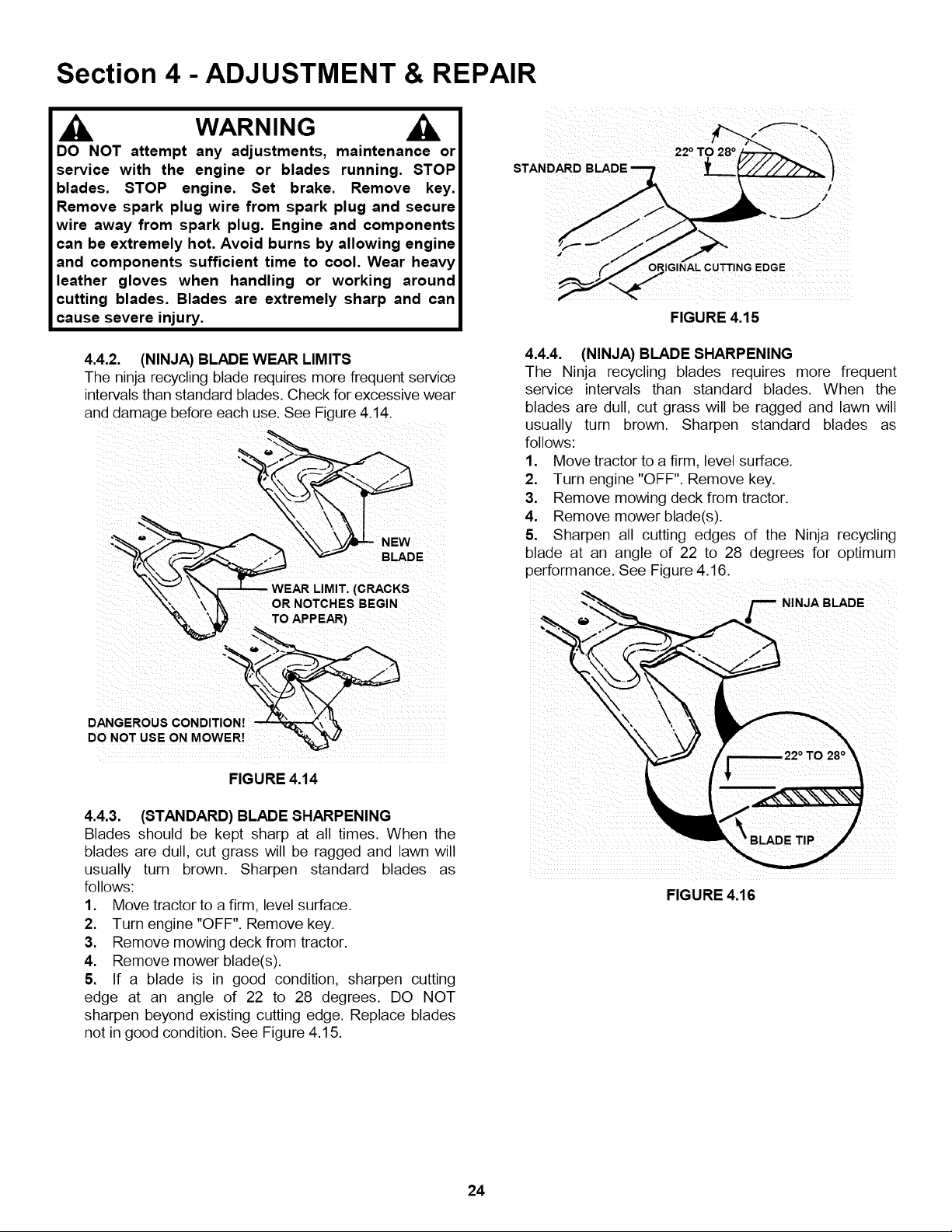
4.4.2. (NINJA) BLADEWEAR LIMITS
The ninja recycling blade requires more frequent service
intervals than standard blades. Check for excessive wear
and damage before each use. See Figure 4.14.
WEAR LIMIT. (CRACKS
OR NOTCHES BEGIN
DANGEROUS
DO NOT USE ON MOWER!
FIGURE 4.14
4.4.4. (NINJA) BLADE SHARPENING
The Ninja recycling blades requires more frequent
service intervals than standard blades. When the
blades are dull, cut grass will be ragged and lawn wilt
usually turn brown. Sharpen standard blades as
follows:
1. Move tractor to a firm. level surface.
2. Turn engine "OFF". Remove key.
3. Remove mowing deck from tractor.
4. Remove mower blade(s).
5. Sharpen all cutting edges of the Ninja recycling
blade at an angle of 22 to 28 degrees for optimum
perform ance. See Figure 4.16.
F NINJA BLADE
4.4.3. (STANDARD) BLADE SHARPENING
Blades should be kept sharp at all times. When the
blades are dull, cut grass will be ragged and lawn will
usually turn brown. Sharpen standard blades as
follows:
1. Move tractor to a firm, level surface.
2. Turn engine "OFF". Remove key.
3. Remove mowing deck from tractor.
4. Remove mower blade(s).
5. If a blade is in good condition, sharpen cutting
edge at an angle of 22 to 28 degrees. DO NOT
sharpen beyond existing cutting edge. Replace blades
not in good condition. See Figure 4.15.
TIP
FIGURE 4.16
24
Section 4 - ADJUSTMENT & REPAIR
WARNING
DO NOT attempt any adjustments, maintenance or
service with the engine or blades running. STOP
blades. STOP engine. Set brake. Remove key.
Remove spark plug wire from spark plug and secure
wire away from spark plug. Engine and components
can be extremely hot. Avoid burns by allowing engine
and components sufficient time to cool. Wear heavy
leather gloves when handling or working around
cutting blades. Blades are extremely sharp and can
cause severe injury.
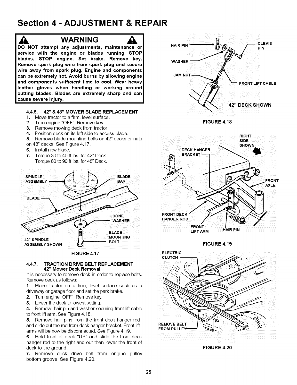
4.4.5. 42" & 48" MOWER BLADE REPLACEMENT
1. Move tractor to a firm, level surface.
2. Turn engine "OFF". Remove key.
3. Remove mowing deck from tractor.
4. Position deck on its left side to access blade.
5. Remove blade mounting bolts on 42" decks or nuts
on 48" decks. See Figure 4.17.
6. Install new blade.
7. Torque 30 to 40 ft Ibs. for 42" Deck.
Torque 80 to 90 ft Ibs. for 48" Deck.
NUT
42,, DECK SHOWN
FIGURE 4.18
RIGHT
SIDE
SHOWN
SPINDLE BLADE
CONE
WASHER
MOUNTING
BOLT
FIGURE 4.17
4.4.7. TRACTION DRIVE BELT REPLACEMENT
42" Mower Deck Removal
It is necessary to remove deck in order to replace belts.
Remove deck as follows:
1. Place tractor on a firm, level surface such as a
driveway or garage floor and set the park brake.
2. Turn engine "OFF". Remove key.
3. Lower the deck to lowest setting.
4. Remove hair pin and washer securing front lift cable
to front liftarm. See Figure 4.18.
5. Remove hair pins from the front deck hanger rod
and slide out the rod from deck hanger bracket. Front lift
arms will be now be disconnected. See Figure 4.19.
6. Hold front of deck "UP" and slide the front deck
hanger rod to the right and out then lower the front of
deck to the ground.
7. Remove deck drive belt from engine pulley
bottom groove. See Figure 4.20.
s
FRONT DECK
HANGER ROD
ELECTRIC
FRONT
FRONT
LIFT ARM
FIGURE 4.19
FIGURE 4.20
25
Section 4 - ADJUSTMENT & REPAIR
WARNING
DO NOT attempt any adjustments, maintenance or
service with the engine or blades running. STOP
blades. STOP engine. Set brake. Remove key.
Remove spark plug wire from spark plug and secure
wire away from spark plug. Engine and components
can be extremely hot. Avoid burns by allowing engine
and components sufficient time to cool.
4.4.7. TRACTION DRIVE BELT REPLACEMENT
42" Mower Deck Removal
(Continued From Previous Page)
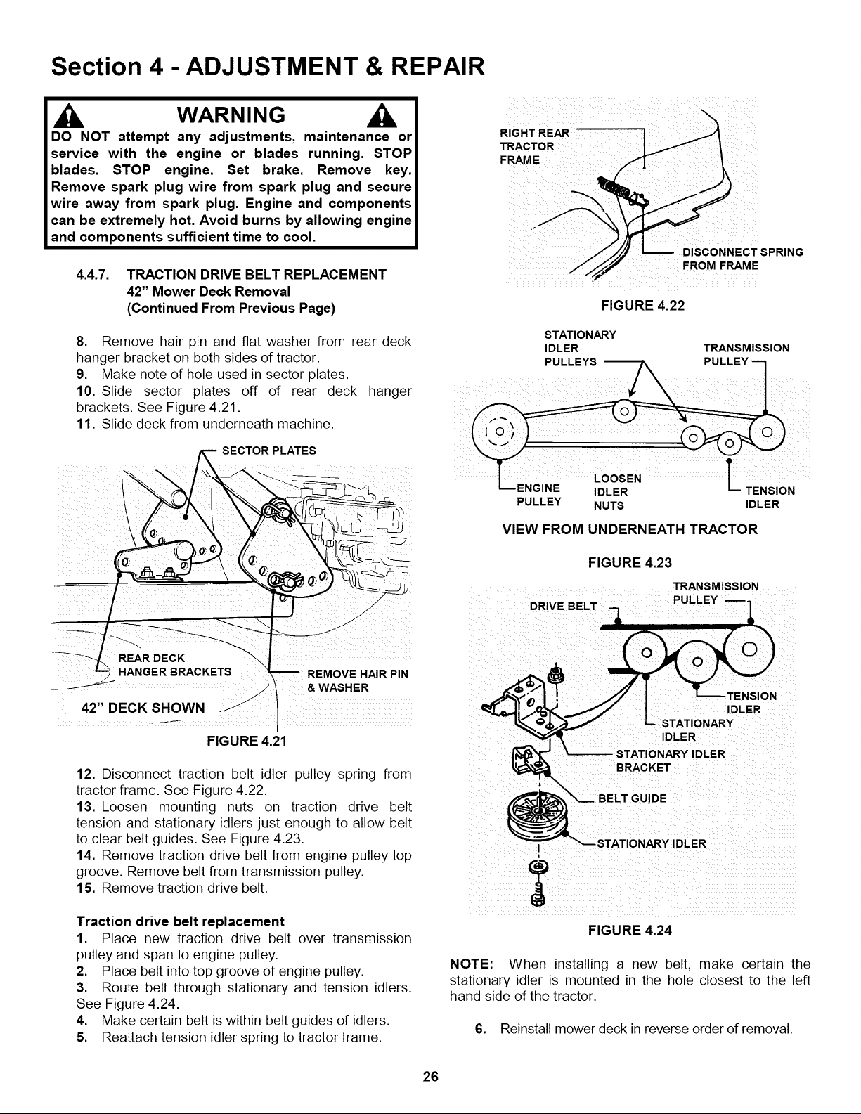
RIGHT REAR ....
TRACTOR
FRAME
DISCONNECT SPRING
FROM FRAME
FIGURE 4.22
8. Remove hair pin and flat washer from rear deck
hanger bracket on both sides of tractor.
9. Make note of hole used in sector plates.
10. Slide sector plates off of rear deck hanger
brackets. See Figure 4.21.
11. Slide deck from underneath machine.
i_ i __i__ _ _ _i!i_i_!__i_i_ii_
.....
FIGURE 4.21
12. Disconnect traction belt idler pulley spring from
tractor frame. See Figure 4.22.
13. Loosen mounting nuts on traction drive belt
tension and stationary idlers just enough to allow belt
to clear belt guides. See Figure 4.23.
14. Remove traction drive belt from engine pulley top
groove. Remove belt from transmission pulley.
15. Remove traction drive belt.
STATIONARY
IDLER TRANSMISSION
IDLER
PULLEY NUTS IDLER
VIEW FROM UNDERNEATH TRACTOR
FIGURE 4.23
TRANSMISSION
DRIVE BELT
tENSION
IDLER
STATIONARY
IDLER
STATIONARY IDLER
BRACKET
I STATIONARY IDLER
Traction drive belt replacement
1. Place new traction drive belt over transmission
pulley and span to engine pulley.
2. Place belt into top groove of engine pulley.
3. Route belt through stationary and tension idlers.
See Figure 4.24.
4. Make certain belt is within belt guides of idlers.
5. Reattach tension idler spring to tractor frame.
FIGURE 4.24
NOTE: When installing a new belt, make certain the
stationary idler is mounted in the hole closest to the left
hand side of the tractor.
6. Reinstall mower deck in reverse order of removal.
26

Section 4 - ADJUSTMENT & REPAIR
WARNING
DO NOT attempt any adjustments, maintenance or
service with the engine or blades running. STOP
blades. STOP engine. Set brake. Remove key.
Remove spark plug wire from spark plug and secure
wire away from spark plug. Engine and components
can be extremely hot. Avoid burns by allowing engine
and components sufficient time to cool.
4.4.7. TRACTION DRIVE BELT REPLACEMENT
48" Mower Deck Removal
RemoveItis necessarydeck asto follows:remove deck in order to replace belts.
1. Place tractor on a firm, level surface such as a
driveway or garage floor and set the park brake.
2. Turn engine "OFF". Remove key.
3. Lower the deck to lowest setting.
4. Disconnect the front lift rod assembly from the
front hanger bracket. See Figure 4.25.
5. Remove hair pins from the front deck hanger
rod and slide out the rod from deck hanger bracket.
Front lift arms will be now be disconnected. See
Figure 4.26.
BELL CRANK
DECK HANGER......
FRONT DECK"
HANGER ROD
ELECTRIC
CLUTCH
SIDE
SHOWN
FRONT
FRONT
LIFT ARM
FIGURE 4.26
HAIR PIN LIFT
LEVER
LIFT ROD
CLEVIS
48" DECK SHOWN
FIGURE 4.25
6. Turn the front wheels to the left.
7. Hold front of deck "UP" and slide the front deck
hanger rod to the right and out then lower the front of
deck to the ground.
8. Remove deck drive belt from engine pulley
bottom groove. See Figure 4.27.
DECK
DRIVE
BELT
FIGURE 4.27
(Continued On Next Page)
27
 Loading...