

Page 1
Safety Instructions & Operator's Manual for
LAWN TRA CTORS
ELECTRIC CLUTCH
SERIES D
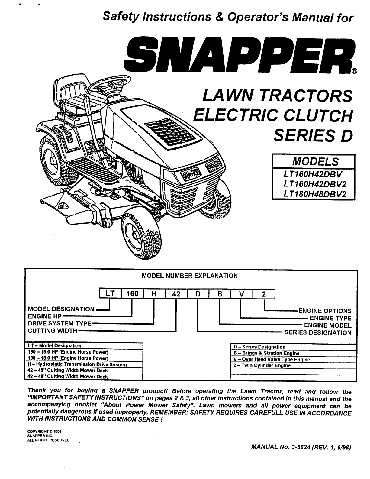
MODELS
LT160H42DBV
L T160H42DB V2
L T180H48DB V2
MODEL NUMBER EXPLANATION
l LT I 160I I
oo ,o T,ON--JI
ENGINE HP
DRIVE SYSTEM TYPE
CUTTING WIDTH
LT- ModelDesiqnation I
160- 16.0HP(EngineHorsePower)
180 - 18.0 HP (Engine Horse Power)
H - Hydrostatic Transmission Drive System
42 - 42" Cutting Width Mower Deck
48 -48" Cutting Width Mower Deck
Thank you for buying a SNAPPER product! Before operating the Lawn Tractor, read and follow the
"IMPORTANT SAFETY INSTRUCTIONS" on pages 2 & 3, all other instructions contained in this manual and the
accompanying booklet "About Power Mower Safety". Lawn mowers and all power equipment can be
potentially dangerous if used improperly. REMEMBER: SAFETY REQUIRES CAREFULL USE IN ACCORDANCE
WITH INSTRUCTIONS AND COMMON SENSE !
COPYRIGHT © 1998
SNAPPER INC.
ALL RIGHTS RESERVED
11421=
ENGINE OPTIONS
ENGINE TYPE
ENGINE MODEL
SERIES DESIGNATION
D - Series Desicjnation
B - Briggs & Stratton Enqine
V - Over Head Valve Type Engine
2 - Twin Cylinder Engine
I
MANUAL No. 3.5624 (REV. 1, 6/98)
Page 2

IMPORTANT SAFETY INSTRUCTIONS
WARNING: This powerful cutting machine is capable of amputating hands and feet and can throw objects that
can cause injury and damagel Failure to comply with the following SAFETY instructions could result in
serious injury or death to the operator or other persons. The owner of the machine must understand these
instructions and must allow only persons who understand these instructions to operate machine. Each
person operating the machine must be of sound mind and body and must not be under the influence of any
substance which might impair vision, dexterity or judgment. If you have any questions pertaining to your
machine which your dealer cannot answer to your satisfaction, call or write the Customer Service Department
at SNAPPER, McDonough, Georgia 30253. Phone: (1-800-935-2967).
PROTECTION FOR CHILDREN
Tragic accidents can occur if the operator is not alert
to the presence of children. Children are often
attracted to the machine and the mowing activity.
Never assume that children will remain where you
last saw them.
1. KEEP children out of the mowing area and under
the watchful care of a responsible adult.
2. DO NOT allow children in yard when machine is
operated (even with the blade OFF).
3. DO NOT allow children or other passengers to
ride on machine or on attachments (even with the
blade OFF). They may fall and be seriously
injured.
4. DO NOT allow pre-teenage children to operate
machine.
5. ALLOW only responsible adults & teenagers with
mature judgment under close adult supervision to
operate machine.
6. BE SURE the area is clear of others before
mowing and turn machine OFF if anyone enters
the area.
7. DO NOT mow in reverse unless absolutely
necessary. LOOK BEHIND and down for small
children before and when backing.
8. USE EXTRA CARE when approaching blind
corners, shrubs, trees, or other objects that may
obscure vision.
PROTECTION AGAINST TIPOVERS
Slopes are a major factor related to loss-of-control
and tip-over accidents, which can result in severe
injury or death. All slopes require extra CAUTION. If
you cannot back up the slope or if you feel uneasy on
it, DO NOT mow it. Use extra care with grass catchers
or other attachments; these can change the stability
of the machine.
1. DO NOT operate machine on slopes exceeding 15
degrees (27% grade).
2. Exercise EXTREME CAUTION on slopes above 10
degrees (18% grade). Turn blade OFF when
traveling uphill. Use first speed and avoid sudden
or sharp turns.
3. DO NOT mow back and forth across face of
slopes. Mow up and down.
PROTECTION AGAINST TIPOVERS
(Continued From Previous Column)
4. AVOID uphill starts. If machine stops going uphill
or tires lose traction, turn blade OFF and back
slowly down the slope.
5. STAY ALERT for holes and other hidden hazards.
Tall grass can hide obstacles. Keep away from
ditches, washouts, culverts, fences and
protruding objects.
6. KEEP A SAFE DISTANCE (at least 3 feet) away
from edge of ditches and other drop offs. The
mower could turn over if an edge caves in.
7. Always begin forward motion in the #1 speed
position.
8. Use weights or a weighted load carrier in
accordance with instructions with a grass catcher
on slopes above 10 degrees (18% grade).
9. DO NOT put your foot on the ground to try to
stabilize the machine.
10. DO NOT mow on wet grass. Reduced traction
could cause sliding.
11. DO NOT mow under any condition where traction,
steering or stability is doubtful without first test
driving over the terrain with blade OFF.
PREPARATION
1. Read this manual, get to know where all controls
are located and practice how to use them before
starting for the first time, and at the beginning of
each season. Read and follow Warnings and
Instructions on engine and machine. Read and
follow operator's manual and instructions
furnished with attachments.
2. Only mature, responsible persons shall operate
the machine and only after proper instruction.
3. Handle fuel with extra care. Fuels are flammable
and vapors are explosive. Use only an approved
fuel container. Never remove fuel cap or add fuel
with engine running. Add fuel outdoors only with
engine stopped and cool. Clean spilled fuel from
machine. DO NOT smoke.
4. Practice operation of machine with BLADE OFF to
learn controls and develop skills.
(Continued on Next Page)
2
Page 3
IMPORTANT SAFETY INSTRUCTIONS
PREPARATION
(Continued From Previous Page)
5. Check the area to be mowed and remove all
objects such as toys, wire, rocks, limbs and other
objects that could cause injury if thrown by blade
or interfere with mowing.
6. Keep people and pets a safe distance from
machine.
7. Check shields, deflectors, switches, blade
controls and other safety devices frequently for
proper operation and location.
8. Make sure all safety decals are clearly legible.
Replace if damaged.
9. Protect yourself when mowing and wear safety
glasses, long pants and substantial footwear.
10. Know how to STOP blade and engine quickly in
preparation for emergencies.
1t. Use extra care when loading or unloading the
machine into a trailer or truck.
12. Check grass catcher components frequently for
signs of wear or deterioration and replace as
needed to prevent injury from thrown objects
going through weak or worn spots.
OPERATION
1. Mount and dismount machine from left side.
2. Start engine from operator's seat, if possible.
Make sure blade is OFF and parking brake is set.
3. STOP blade, STOP engine, set parking brake and
remove key when leaving machine.
4. DO NOT operate machine unless properly seated
with feet on feet rests or pedal(s).
5. STOP BLADE and ENGINE and make sure blade
has stopped before removing grass catcher or
unclogging mower to prevent loss of fingers or
hand.
6. Blade must be OFF except when cutting grass.
Set blade in highest position when mowing over
rough ground.
7. Keep hands and feet away from rotating blade
underneath deck. NEVER place foot on ground
while BLADE is ON or machine is in motion.
8. Deflector or entire grass catcher must be in place.
NEVER point discharge at people, passing cars,
windows or doors.
9. Slow down before turning.
10. Watch out for traffic when near or crossing
roadways.
11. STOP engine immediately after striking an
obstruction. Inspect machine and repair damage
before resuming operation.
12. Mow only in daylight or with good artificial light.
13. Move joystick (if equipped) SLOWLY to maintain
control during speed and directional changes.
14. Exercise CAUTION when pulling loads. Limit
loads to those you can safely control and attach
loads to hitch plate as specified with SNAPPER
attachment instructions.
MAINTENANCE
1. Never store machine or fuel container inside
where fumes may reach an open flame, spark or
pilot light such as in a water heater, furnace,
clothes dryer or other gas appliance. Allow
engine to cool before storing machine in an
enclosure. Store fuel container out of the reach of
children in a well ventilated, unoccupied building.
2. Keep engine free of grass, leaves or excess
grease to reduce fire hazard and engine
overheating.
3. When draining fuel tank, drain fuel into an
approved container outdoors and away from open
flame.
4. Check brakes frequently; adjust, repair or replace
as needed.
5. Keep all bolts, nuts and screws properly tight.
Check that all cotter pins are in proper position.
6. Always provide adequate ventilation when
running engine indoors. Exhaust gases contain
carbon monoxide, an odorless and deadly
poison.
7. Disconnect negative (black) cable from battery
before performing maintenance or service.
Cranking engine could cause injury.
8. Never work under machine without safety blocks.
9. Service engine and make adjustments only when
engine is stopped. Remove spark plug wire(s)
from spark plug(s) and secure wire(s) away from
spark plug(s).
10. DO NOT change engine governor speed settings
or overspeed engine.
11. Lubricate machine at intervals specified in
manual to prevent controls from binding.
12. Mower blades are sharp and can cut. Wrap the
blades or wear heavy leather gloves and use
CAUTION when handling them.
13. NEVER test for spark by grounding spark plug
next to spark plug hole; spark plug could ignite
gas exiting engine.
14. Have machine serviced by an authorized
SNAPPER dealer at least once a year and have the
dealer install any new safety devices.
15. Use only genuine SNAPPER replacement parts to
assure that original standards are maintained.
3
Page 4
TABLE OF CONTENTS
IMPORTANT SAFETY INSTRUCTIONS ............ 2-3
TABLE of CONTENTS ......................................... 4
FAMILIARIZATION ............................................. 5-6
Serial & Model Number Location ....................... 5
Controls .............................................................. 5
Components ...................................................... 6
OPERATING INSTRUCTIONS ........................ 7-11
Pre-start Checklist ............................................. 7
Adjusting Operator's Seat .................................. 7
Starting & Stopping Engine .............................. 7-8
Starting & Stopping Wheel Drive ........................ 9
Setting & Releasing Parking Brake ..................... 9
Starting & Stopping Mower Blades ...................... 9
Adjusting Cutting Height ................................... 10
Tips on Mowing ................................................. 10
Raising Chute Deflector .................................... 10
Rolling Tractor With Engine Off ........................ 11
ACCESSORIES .................................................. 11
TROUBLESHOOTING GUIDE ....................... 12-13
MAINTENANCE INSTRUCTIONS ................. 14-29
Service Schedule ......................................... 14
Maintenance Parts ....................................... 14
Hydrostatic Transmission Oil .................... 15
To Check Oil Level ........................................ 15
Changing Engine Oil ................................... 16
Lubrication (Tractor) .............................. 16-17
Front Wheel Bearings .................................... 16
Axle Spindles ................................................. 16
Steering Shaft ................................................. 16
Clutch/Brake Pivot ......................................... 17
Steering Sector Gear ..................................... 17
Steering Drag Link......................................... 17
Steering Tie Rod............................................ 17
Park Brake Latch ........................................... 17
Deck Lift Mechanism ..................................... 17
Mower Deck Spindles ..................................... 17
Engine Service ............................................. 18
Engine Air Pre-Cleaner .................................. 18
Engine Air Cleaner ........................................ 18
Spark Plug ..................................................... 18
Fuel Filter ...................................................... 18
Engine Cooling System ................................. 18
MAINTENANCE INSTRUCTIONS (Continued)
Battery Service .................................................. 19
Battery Electrolyte Check .............................. 19
Battery Removal ............................................ 19
Battery Charging............................................ 19
Activating New Battery .................................. 19
Mower Deck Removal/Reinstallation .......... 20-21
Standard Mower Blade Service .............. ..... 21-22
Standard Blade Wear Limits ..................... 21
Blade Removal/Replacement ........................ 21
42" Mower Blade............................................ 21
Sharpening Standard Blade(s) ............ :.. 21 & 22
Ninja Mower Blade Service .................................. 22
Ninja Blade Wear Limits ............................ 22
Ninja Blade Sharpening ............................. 22
Belt Service .................................................. 23-24
Mower Drive Belt Removal/Replacement 23
42 _Deck Drive Belt ...................................... 23
Traction Drive Belt Service .......................... 24
Traction Drive Belt Removal ..................... 24
Traction Drive Belt Replacement .............. 24
Traction Drive Belt Adjustment ................. 25
Deck Level Adjustment ................................ 25-27
Tires & Pressure ............................................ 25
Side to Side Level .................................... 25-26
Front to Rear Level ........................................ 27
Sector Plates ............................................ 27
Front Lift Cable ......................................... 27
Shifter Adjustment ............................................ 28
Steering Adjustment ......................................... 28
Wheel Brake Adjustment .................................. 29
Blade Brake Note .............................................. 29
ELECTRICAL SYSTEM ................................. 30-31
20 Amp Fuse Protection ................................ 30
DIAGRAMS, Single Cylinder Models ............. 30
DIAGRAMS, Twin Cylinder Models ................ 31
WARRANTY ....................................................... 32
PRIMARY MAINTENANCE ............................ 33-36
4
Page 5
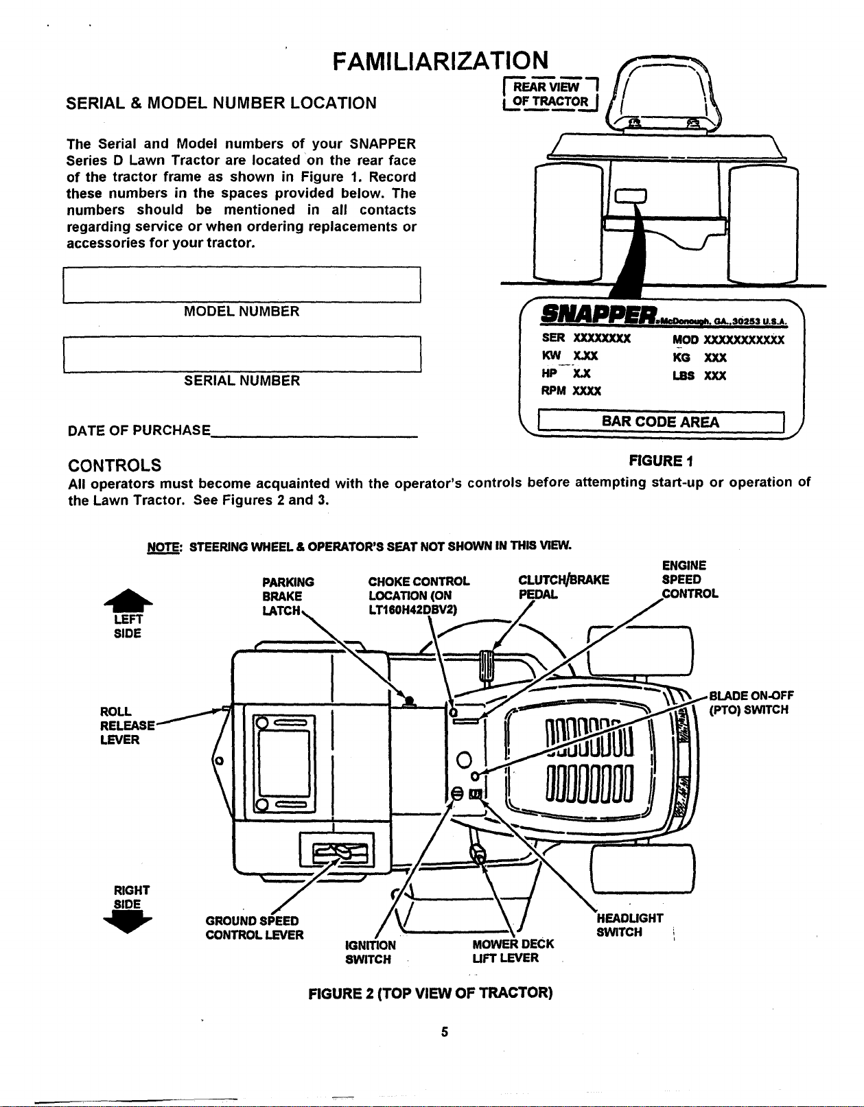
FAMILIARIZATION
The Serial and Model numbers of your SNAPPER
Series D Lawn Tractor are located on the rear face
of the tractor frame as shown in Figure 1. Record
these numbers in the spaces provided below. The
numbers should be mentioned in all contacts
regarding service or when ordering replacements or
accessories for your tractor.
I
MODEL NUMBER
L
SERIAL NUMBER
i oFTRACTORISERIAL & MODEL NUMBER LOCATION
SER XXXXXXXX MODXXXXXXXXXXX
KW X=XX KG XXX
Hp--x.X ,-s xxx
RPM XXXX
% , ,
v
DATE OF PURCHASE
BAR CODE AREA 11
i
CONTROLS FIGURE t
All operators must become acquainted with the operator's controls before attempting start-up or operation of
the Lawn Tractor. See Figures 2 and 3.
_: STEERING WHEEL & OPERATOR'S SEAT NOT SHOWN IN THIS VIEW.
ENGINE
CLUTCH/BRAKE SPEED
ON-OFF
(PTO) SWITCH
LEFT
SIDE
ROLL
RELEASE
LEVER
PARKING CHOKE CONTROL
BRAKE LOCATION (ON PEDAL
LTI60H42DBV2)
RIGHT
SIDE
/
GROUND SPEED
CONTROL LEVER
HEADUGHT
SWITCH
IGNITION MOWERDECK
SWITCH UFT LEVER
FIGURE 2 (TOP VIEW OF TRACTOR)
Page 6
FAMILIARIZATION
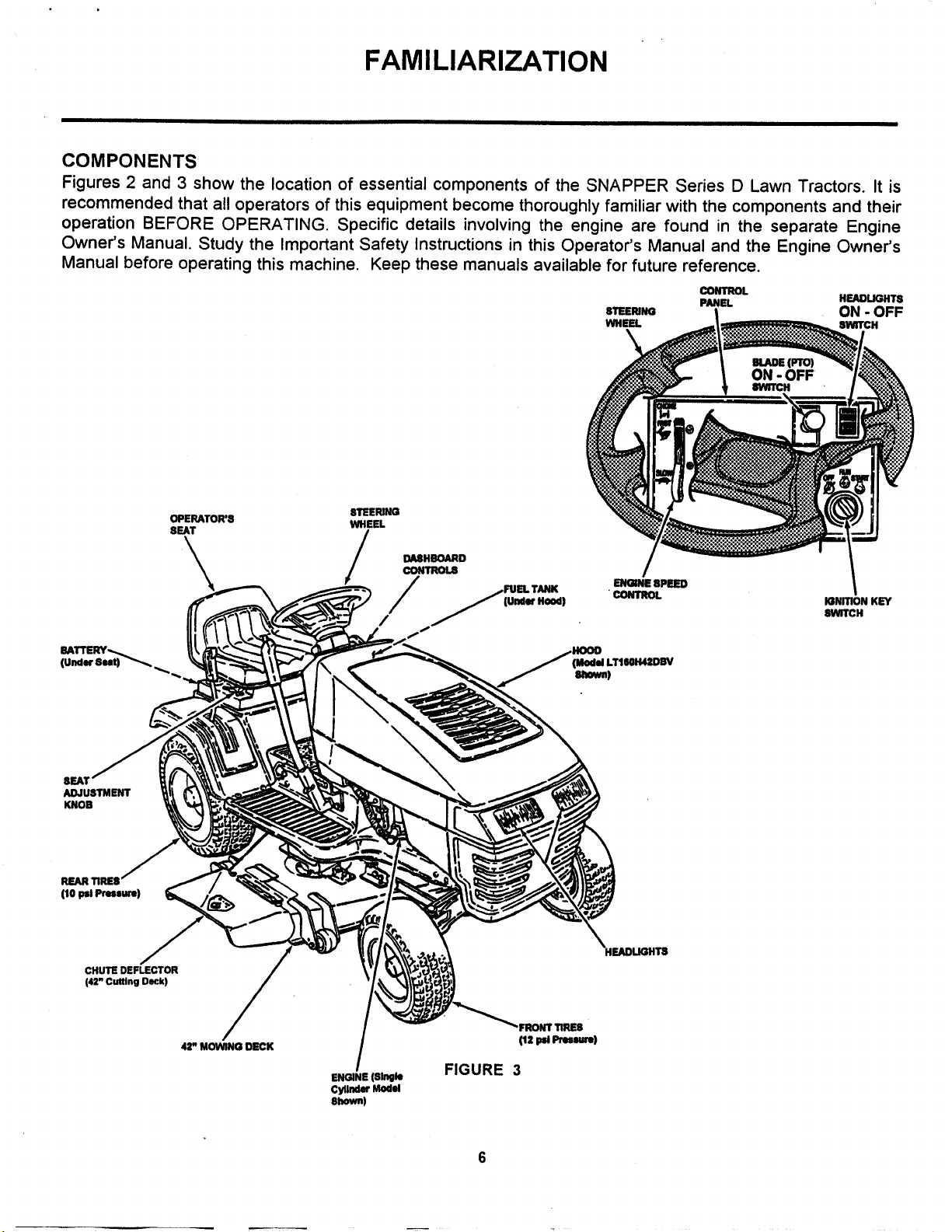
COMPONENTS
Figures 2 and 3 show the location of essential components of the SNAPPER Series D Lawn Tractors. It is
recommended that all operators of this equipment become thoroughly familiar with the components and their
operation BEFORE OPERATING. Specific details involving the engine are found in the separate Engine
Owner's Manual. Study the Important Safety Instructions in this Operator's Manual and the Engine Owner's
Manual before operating this machine. Keep these manuals available for future reference.
CONTROL
s_imt_ ON - OFF
WHEEL 8WITCH
PANEL HEADLIGHTs
ADJUSTMENT
KNOB
REARTIRES
(10psiPressure)
OPERATOR'8
8EAT
\ /
8TEERING
WHEEL
DASHBOARD
CONTROLS
_.FUEL TANK
/ _JlUndw Hood)
ENGINE8PEED
CONTROL
(Model LTI60H4ZDBV
IGNITION KEY
8WITCH
CHUTE DEFLECTOR
(42" Cutting Deck)
42' MOWING DECK
ENGINE (Single
Cylinder Model
(12 psi Pressure)
FIGURE 3
Page 7
OPERATING INSTRUCTIONS
PRE-START CHECKLIST
Make the following checks and perform service
as required before each start.up.
Check tires and add air as needed to bring pressure to
12 psi in front tires and 10 psi in rear tires.
Check guards, deflectors and covers to make sure all
are in place and securely tightened. If guards are
missing or damaged, replace before operating mower.
Check operator's seat readjust as needed following
instructions in the next column on this page.
Clean exterior surfaces of cutting deck, engine and
tractor from any accumulation of grass clippings and
debris. Keep engine air intake screens and cooling fins
clean at all times.
Raise Hood by lifting lower rear edges until spring latch
releases then tilt hood forward.
Check engine oil. Add oil as needed to bring up to, but
not over, the full mark. Refer to the Engine Owner's
Manual for oil specifications.
ADJUSTING OPERATOR'S SEAT
With engine "OFF", raise operator's seat and loosen the
two adjusting knobs on the seat support. See Figure 5.
\
LOOSENADJUSTING
KNOBSTOADJUST /
SEAT
FIGURE 5
/
I
With engine "OFF", move the tractor outside, raise
hood and add fuel to the fuel tank. Securely tighten fuel
cap after refueling. See figure 4. Refer to Engine
Owner's Manual for fuel specifications. Lower hood.
TIGHTEN CAP
AFTER FILLING
TANK
FUEL
Lower the seat.
Sit in the operator's seat and slide the seat forward or
backward until the clutch/brake pedal can be fully
depressed comfortably.
Raise seat and tighten the adjusting knobs to secure
seat in position.
STARTING & STOPPING ENGINE
STARTER INTERLOCK NOTE:
Engine will not start if :
1. BLADE (PTO) SWITCH is in ON position.
2. PARK BRAKE NOT set or CLUTCH/BRAKE pedal
is NOT fully depressed.
OPERATOR PRESENCE CONTROL NOTE:
FIGURE 4
Engine will shut down if operator leaves the seat
without :
1. Pushing the BLADE (PTO) SWITCH "IN" to the
OFF position.
2. Setting the PARK BRAKE LEVER.
Page 8
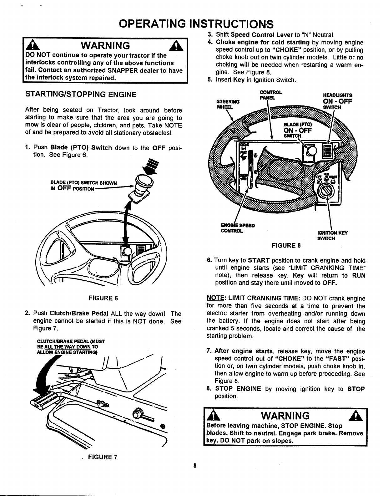
OPERATING INSTRUCTIONS
WARNING
DO NOT continue to operate your tractor if the
interlocks controlling any of the above functions
fail. Contact an authorized SNAPPER dealer to have
the interlock system repaired.
3. Shift Speed Control Lever to "N" Neutral.
4. Choke engine for cold starting by moving engine
speed control up to "CHOKE" position, or by pulling
choke knob out on twin cylinder models. Little or no
choking will be needed when restarting a warm en-
gine. See Figure 8.
5. Insert Key in Ignition Switch.
STARTING/STOPPING ENGINE
After being seated on Tractor, look around before
starting to make sure that the area you are going to
mow is clear of people, children, and pets. Take NOTE
of and be prepared to avoid all stationary obstacles!
1. Push Blade (PTO) Switch down to the OFF posi-
tion. See Figure 6.
BLADE (PTO) SWITCH SHOWN
iN OFF POSmON-- _--
CONTROL
STEERING ON - OFF
WHEEL 8WITCH
PANEL HEADUGHTS
ON - OFF
ENGINE 8PEED
CONTROL
IGNmONKEY
_WrCH
FIGURE 8
6. Turn key to START position to crank engine and hold
until engine starts (see "LIMIT CRANKING TIME"
note), then release key. Key will return to RUN
position and stay there until moved to OFF.
FIGURE 6
2. Push Clutch/Brake Pedal ALL the way down! The
engine cannot be started if this is NOT done. See
Figure 7.
CLUTCHIBRAKE PEDAL (MUST
BE ALL THE WA Y DOWN TO
FIGURE 7
NOTE: LIMIT CRANKING TIME: DO NOT crank engine
for more than five seconds at a time to prevent the
electric starter from overheating and/or running down
the battery. If the engine does not start after being
cranked 5 seconds, locate and correct the cause of the
starting problem.
7. After engine starts, release key, move the engine
speed control out of "CHOKE" to the "FAST" posi-
tion or, on twin cylinder models, push choke knob in,
then allow engine to warm up before proceeding. See
Figure 8.
8. STOP ENGINE by moving ignition key to STOP
position.
Before leaving machine, STOP ENGINE. Stop
blades. Shift to neutral. Engage park brake. Remove
WARNING
key. DO NOT park on slopes.
Page 9
OPERATING INSTRUCTIONS
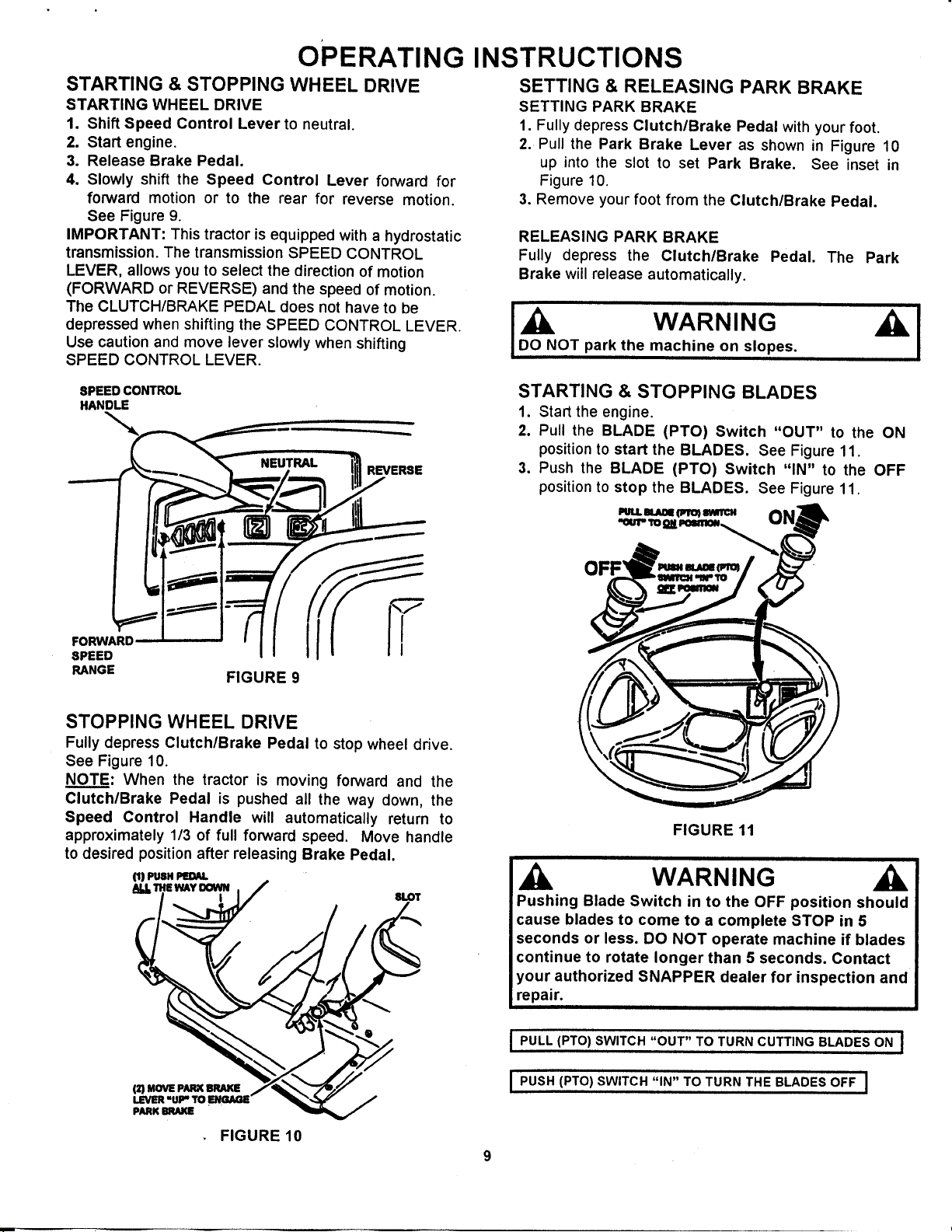
STARTING & STOPPING WHEEL DRIVE
STARTING WHEEL DRIVE
1. Shift Speed Control Lever to neutral.
2. Start engine.
3. Release Brake Pedal.
4. Slowly shift the Speed Control Lever forward for
forward motion or to the rear for reverse motion.
See Figure 9.
IMPORTANT: This tractor is equipped with a hydrostatic
transmission. The transmission SPEED CONTROL
LEVER, allows you to select the direction of motion
(FORWARD or REVERSE) and the speed of motion.
The CLUTCH/BRAKE PEDAL does not have to be
depressed when shifting the SPEED CONTROL LEVER.
Use caution and move lever slowly when shifting
SPEED CONTROL LEVER.
SPEED CONTROL
HANDLE
REVERSE
SETTING & RELEASING PARK BRAKE
SETTING PARK BRAKE
1. Fully depress Clutch/Brake Pedal with your foot.
2. Pull the Park Brake Lever as shown in Figure 10
up into the slot to set Park Brake. See inset in
Figure 10.
3. Remove your foot from the Clutch/Brake Pedal.
RELEASING PARK BRAKE
Fully depress the Clutch/Brake Pedal. The Park
Brake will release automatically.
IDo_o N WARNING
OT park the machine on slopes.
STARTING & STOPPING BLADES
1. Start the engine.
2. Pull the BLADE (PTO) Switch "OUT" to the ON
positionto start the BLADES. See Figure 11.
3. Push the BLADE (PTO) Switch "IN" to the OFF
positionto stop the BLADES. See Figure 11.
IIUIJ. 81.AI0mfl=qro_II1MTCX
FORWARD
SPEED
RANGE
FIGURE 9
STOPPING WHEEL DRIVE
Fully depress Clutch/Brake Pedal to stop wheel drive.
See Figure 10.
NOTE: When the tractor is moving forward and the
Clutch/Brake Pedal is pushed all the way down, the
Speed Control Handle will automatically return to
approximately 1/3 of full forward speed. Move handle
to desired position after releasing Brake Pedal.
O)PUSXPm_U.
_j.Txe _y oowN
(2) MOVE PARK BRAKE
PARK BRAKE
I SLOT
FIGURE 10
FIGURE 11
WARNING
Pushing Blade Switch in to the OFF position should
cause blades to come to a complete STOP in 5
seconds or less. DO NOT operate machine if blades
continue to rotate longer than 5 seconds. Contact
your authorized SNAPPER dealer for inspection and
repair.
i PULL (PTO) SWITCH "OUT" TO TURN CUTTING BLADES ON I
I PUSH (PTO) SWITCH "IN" TO TURN THE BLADES OFF I
Page 10
OPERATING
INSTRUCTIONS
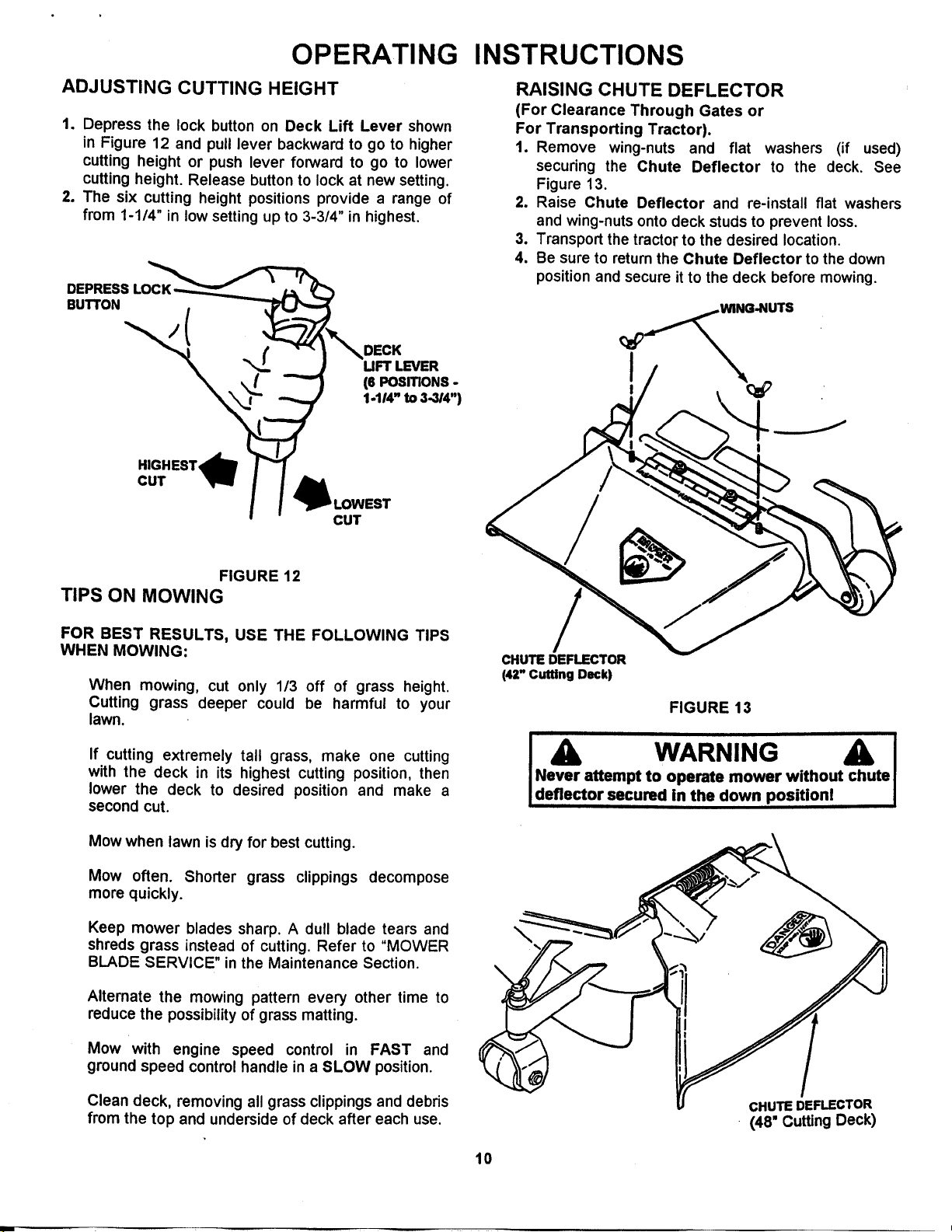
ADJUSTING CUTTING HEIGHT
1. Depress the lock button on Deck Lift Lever shown
in Figure 12 and pull lever backward to go to higher
cutting height or push lever forward to go to lower
cutting height. Release button to lock at new setting.
2. The six cutting height positions provide a range of
from 1-1/4" in low setting up to 3-3/4" in highest,
DEPRESSLOC_
BUTTON
UFT LEVER
HIGHEST,_
CUT
!
_J_ LOWEST
(6 PosmoNs -
1.114" to 3.314")
CUT
RAISING CHUTE DEFLECTOR
(For Clearance Through Gates or
For Transporting Tractor).
1. Remove wing-nuts and flat washers (if used)
securing the Chute Deflector to the deck. See
Figure 13.
2. Raise Chute Deflector and re-install flat washers
and wing-nuts onto deck studs to prevent loss.
3. Transport the tractor to the desired location,
4. Be sure to return the Chute Deflector to the down
position and secure it to the deck before mowing.
__WING.NUTS
FIGURE 12
TIPS ON MOWING
FOR BEST RESULTS, USE THE FOLLOWING TIPS
WHEN MOWING:
When mowing, cut only 113 off of grass height.
Cutting grass deeper could be harmful to your
lawn.
If cutting extremely tall grass, make one cutting
with the deck in its highest cutting position, then
lower the deck to desired position and make a
second cut.
Mow when lawn is dry for best cutting.
Mow often. Shorter grass clippings decompose
more quickly.
Keep mower blades sharp. A dull blade tears and
shreds grass instead of cutting. Refer to "MOWER
BLADE SERVICE" in the Maintenance Section.
Alternate the mowing pattern every other time to
reduce the possibility of grass matting.
CHUTE DEFLECTOR
(42" Cutting Deck)
FIGURE 13
A WARNING A I
Never attempt to operate mower without chute I
deflector secured in the down position! I
\
Mow with engine speed control in FAST and
ground speed control handle in a SLOW position.
Clean deck, removing all grass clippings and debris
from the top and underside of deck after each use.
CHUTE DEFLECTOR
(48" Cutting Deck)
10
Page 11
......................................OPERATING INSTRUCTIONS
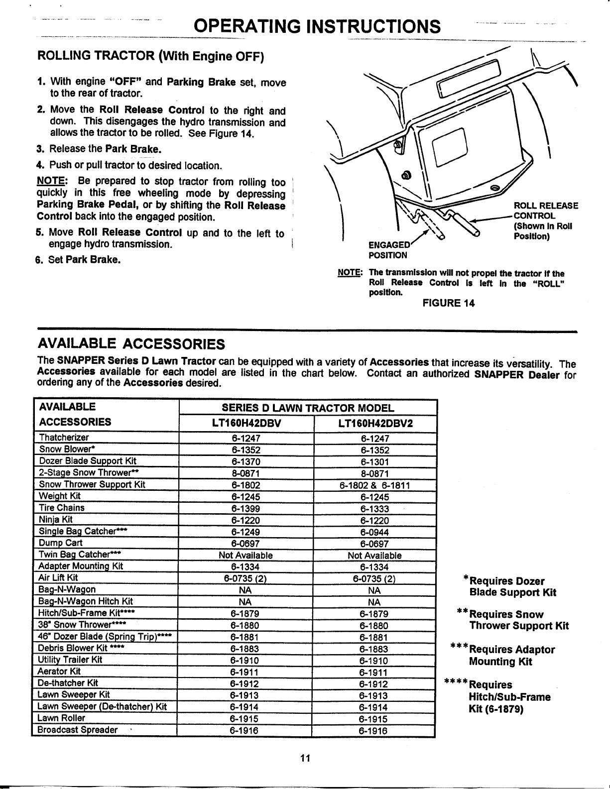
ROLLING TRACTOR (With Engine OFF)
1. With engine "OFF" and Parking Brake set, move
to the rear of tractor.
2. Move the Roll Release Control to the right and
down. This disengages the hydro transmission and
allows the tractor to be rolled. See Figure 14.
3. Release the Park Brake.
4. Push or pull tractor to desired location.
NOTE: Be prepared to stop tractor from rolling too
quickly in this free wheeling mode by depressing
Parking Brake Pedal, or by shifting the Roll Release
Control back into the engaged position.
5. Move Roll Release Control up and to the left to
engage hydro transmission.
6. Set Park Brake.
\
\
ENGAGED'
POSITION
NOT..__E:The transmission will not propel the tractor if the
Roll Release Control Is left in the "ROLL"
position.
FIGURE 14
ROLL RELEASE
(Shown in Roll
Position)
AVAILABLE ACCESSORIES
The SNAPPER Series D Lawn Tractor can be equipped with a variety of Accessories that increase its versatility. The
Accessories available for each model are listed in the chart below. Contact an authorized SNAPPER Dealer for
ordedng any of the Accessories desired.
AVAILABLE
ACCESSORIES
Thatcherizer
Snow Blower*
Dozer Blade Support Kit
2-Stage Snow Thrower**
Snow Thrower Support Kit
Weight Kit
Tire Chains
Ninja Kit
Single Bag Catcher***
Dump Cart
Twin Bag Catcher***
Adapter Mounting Kit
Air Lift Kit
Bag-N-Wagon
Bag-N-Wagon Hitch Kit
Hitch/Sub-Frame Kit****
38" Snow Thrower****
46" Dozer Blade (Spring Trip)****
Debris Blower Kit ****
Utility Trailer Kit
Aerator Kit
De-thatcher Kit
Lawn Sweeper Kit
Lawn Sweeper (De-thatcher) Kit
Lawn Roller
Broadcast Spreader
SERIES D LAWN TRACTOR MODEL
LT160H42DBV
6-1247
6-1352
6-1370
8-0871
6-1802
6-1245
6-1399
6-1220
6-1249
6-0697
Not Available
6-1334
6-0735 (2)
NA
NA
6-1879
6-1880
6-1881
6-1883
6-1910
6-1911
6-1912
6-1913
6-1914
6-1915
6-1916
LT160H42DBV2
6-1247
6-1352
6-1301
8-0871
6-1802 & 6-1811
6-1245
6-1333
6-1220
6-0944
6-0697
Not Available
6-1334
6-0735 (2)
6-1879
6-1880
6-1881
6-1883
6-1910
6-1911
6-1912
6-1913
6-1914
6-1915
6-1916
NA
NA
* Requires Dozer
Blade Support Kit
** Requires Snow
Thrower Support Kit
*** Requires Adaptor
Mounting Kit
** * * Requires
HitchlSub-Frame
Kit (6-1879)
11
Page 12
TROUBLESHOOTING GUIDE (Part 1)
When using the Trouble-Shooting Guides on this page and the next, don't overlook the simplest cause
first, even though it may seem too obvious to consider. For example, if the engine will not start, it simply
may be out of fuel. The Guides generally list the most simple causes first in each problem category to
help you locate the cause through the process of elimination.
PROBLEM
Starter Will Not
Crank Engine
Engine Will Not
Start
Engine Stalls After
Running
Engine Loses
Power
Engine Backfires
When Turned To
"STOP"
Excessive
Vibration
PROBABLE CAUSE
1. Battery dead.
2. Blown fuse.
3. Electrical connections loose or
corroded.
4. Defective ignition switch.
5. Starter Spins without engaging.
1. Blade engagement switch in the
"ON" position.
2. Park brake not set.
3. Fuel tank empty.
4. Engine needs choking.
5. Spark plug wire disconnected.
6. Battery weak or dead.
7. Faulty interlock switch.
1. Operator not in seat.
2. Engine speed control in the
"CHOKE" position.
3. Fuel tank empty.
4. Engine air pre-cleaner and/or
air cleaner dirty.
5. Spark plug defective or gap set
improperly.
6. Fuel filter stopped up.
7. Water, debris or stale fuel in
fuel system.
1. Excessive load on engine.
2. Engine air pre-cleaner or air
cleaner dirty.
3. Engine oil level low.
4. Engine cooling fins and air
screens excessively dirty.
5. Spark plug faulty.
6. Water, debris or stale fuel in
fuel system.
1. Engine speed control set too
"FAST".
1. Damaged or bent mower
blades.
2. Loose blade components.
3. Loose or missing air lift (if
equipped).
CORRECTIVE ACTION
1. Service battery.
2. Replace fuse.
3. Clean and check connections for good
contact.
4. Contact authorized SNAPPER dealer.
5. Release Start key and repeat attempt. If
starter continues to spin, contact Dealer.
1. Move blade engagement switch to
=OFF".
2. Set park brake.
3. Fill fuel tank with fresh fuel.
4. Move engine speed control to "CHOKE".
5. Place spark plug wire onto spark plug.
6. Service battery.
7. Contact authorized SNAPPER dealer.
1. Sit in operator's seat.
2. Move engine speed control to "FAST".
3. Fill with fuel to proper level.
4. Clean free of all debris.
5. Service spark plug.
6. Replace fuel filter.
7. Drain and clean fuel system.
1. Lessen load by slowing ground speed.
2. Clean or replace filters.
3. Fill with engine oil to proper level.
4. Clean free of all debris.
5. Service spark plug.
6. Drain and clean fuel system.
1. Set engine speed control to "SLOW" and
allow engine to idle. Then, turn key to
"OFF".
1. Service mower blade(s).
2. Service and tighten loose parts.
3. Replace air lifts. Tighten to proper
torque.
12
(Continued on next Page)
Page 13
TROUBLESHOOTING GUIDE (Part 2)
PROBLEM
Tractor Will Not
Move Or Loss Of
Traction
Blade(s) Not
Turning
Cutting Grass
Improperly
Poor Grass
Discharge
Battery Will Not
Charge
Oil Leaking From
Transmission
PROBABLE CAUSE
1. Speed control handle in the
neutral "N" position,
2. Roll release control in "ROLL"
position (Hydro Models Only).
3. Low transmission oil level (Hydro
Models Only).
4. Shifter out of adjustment.
5. Traction drive belt requires
adjustment.
6. Traction drive belt requires
replacement.
1. Blade engagement switch in the
"OFF" position.
.....2. Blade belt requires adjustment.
3. Blade belt requires replacement.
4. Electric clutch not functioning.
1. Uneven tire pressure.
2. Cutting height too low or high.
3. Engine speed too slow.
4. Forward speed too fast.
5. Deck side to side level requires
adjustment.
6. Deck front to rear level requires
adjustment.
7. Cutting Blade dull or damaged.
8. Blade belt requires replacement.
9. Blade belt slipping.
1. Engine speed too slow.
2. Forward speed too fast.
3. Grass is wet.
4. Excessively worn or damaged
blade(s}.
5. Build up of grass clippings and
debris under deck.
6. Improper blade(s) installed on
deck.
7. Blade(s) installed improperly on
deck.
1. Poor cable connections.
2. Bad battery cell(s).
3. Faulty alternator.
1. Loose or missing oil filler cap on
transmission.
2. Leaking axle seats.
3. Leaking at casing seal.
CORRECTIVE ACTION
1. Place speed control in desired speed.
2. Move roll release control to the
engaged position.
3. Bring oil to proper level.
4. Adjust shifter.
5. Adjust traction drive belt.
6. Replace traction drive belt.
1. Move switch to the "ON" position.
2. Adjust mower belt.
3. Replace mower belt.
4. Contact authorized SNAPPER dealer.
1. Bring to proper pressure.
2. Adjust cutting height.
3. Move engine speed control to "FAST".
4. Move speed control to a slower speed.
5. Adjust side to side level
6. Adjust front to rear level.
7. Sharpen cutting edges or replace blade.
8. Replace blade belt.
9. Replace blade belt.
1. Move engine speed control to "FAST".
2. Move speed control to a slower speed.
3. Mow when grass is dry.
4. Service mower blade(s).
5. Clean deck.
6. Install proper SNAPPER blades.
7. Install blades properly.
1. Clean cables and battery terminals.
2. Replace with new battery.
3. Contact engine manufacturer's dealer.
1. Check oil level and re-install oil cap.
2. Contact authorized SNAPPER dealer.
3. Contact authorized SNAPPER dealer.
13
Page 14
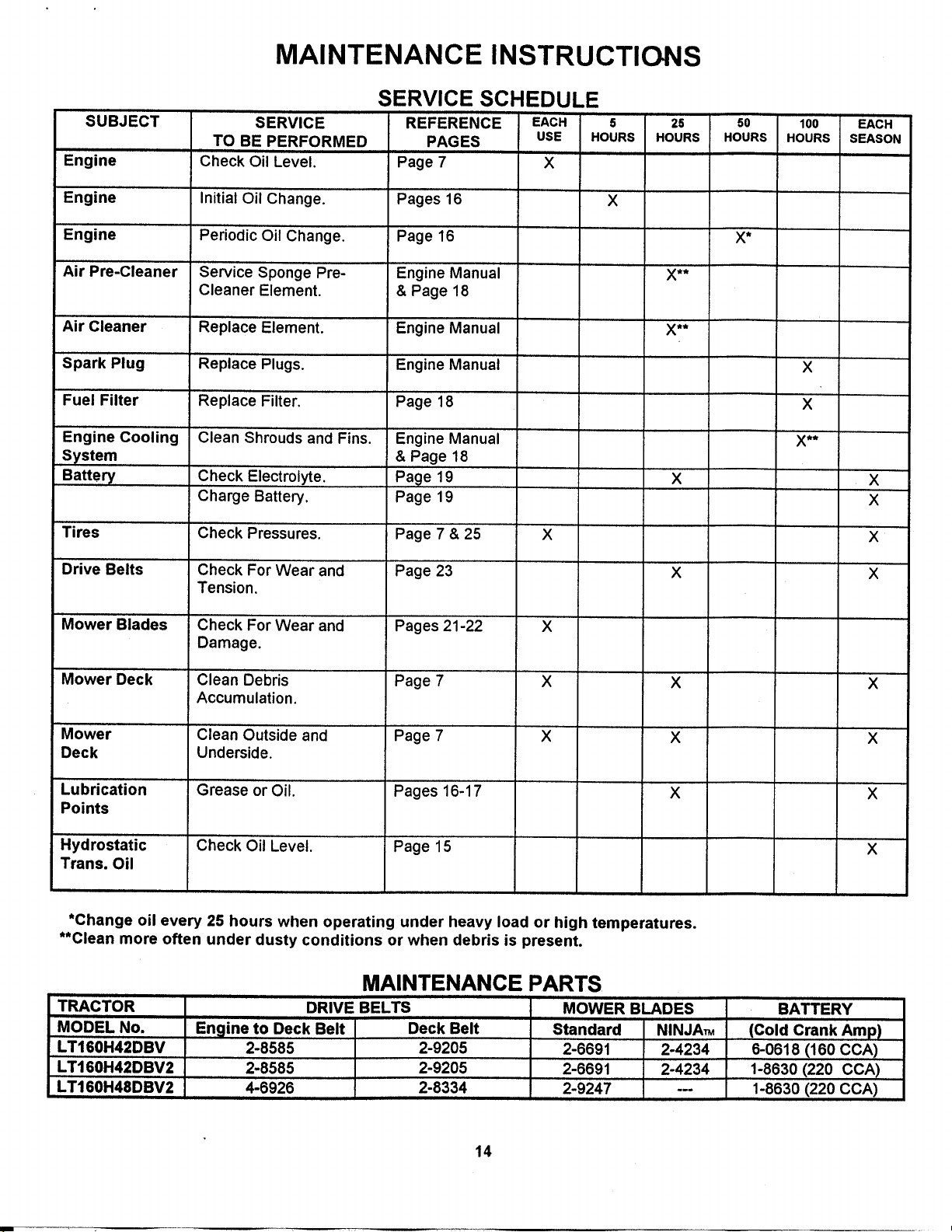
SUBJECT
Engine
MAINTENANCE INSTRUCTIONS
SERVICE SCHEDULE
SERVICE REFERENCE EACH 5 25
TO BE PERFORMED PAGES USE HOURS HOURS
Check Oil Level. Page 7 x
50
HOURS
10o
HOURS
EACH
SEASON
Engine
Engine
Air Pre-Cleaner
Air Cleaner
Spark Plug
Fuel Filter
Engine Cooling
System
Battery
Tires
....Drive Belts
Mower Blades
Initial Oil Change. Pages 16 X
Periodic Oil Change. Page 16
Service Sponge Pre- Engine Manual X**
Cleaner Element. & Page 18
Replace Element. Engine Manual X**
Replace Plugs. Engine Manual
Replace Filter. Page 18
Clean Shrouds and Fins. Engine Manual
& Page 18
Check Electrolyte. Page 19 X
Charge Battery. Page 19
Check Pressures. Page 7 & 25 X
Check For Wear and Page 23 X
Tension.
Check For Wear and Pages 21-22 X
Damage.
_
X
X
X**
X
X
X
X
Mower Deck
Clean Debris Page 7 X X
Accumulation.
Mower
Deck
Lubrication
Clean Outside and Page 7 X X
Underside.
Grease or Oil. Pages 16-17 X
Points
Hydrostatic
Check Oil Level. Page 15
Trans. Oil
*Change oil every 25 hours when operating under heavy load or high temperatures.
**Clean more often under dusty conditions or when debris is present.
MAINTENANCE PARTS
TRACTOR DRIVE BELTS
MODEL No. En_line to Deck Belt Deck Belt
LT160H42DBV 2-8585 2-9205
LT160H42DBV2 2-8585 2-9205
LT160H48DBV2 4-6926 2-8334
MOWER BLADES
Standard NINJA_
2-6691 2-4234
2-6691 2-4234
2-9247 ---
X
X
X
X
BATTERY
(Cold Crank Amp)
6-0618 (160 CCA)
1-8630 (220 CCA)
1-8630 (220 CCA)
14
Page 15
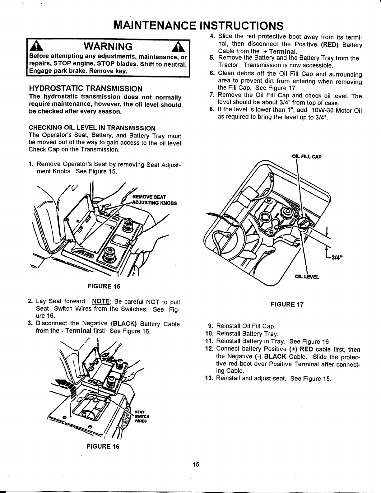
MAINTENANCE INSTRUCTIONS
Before attempting any adjustments, maintenance, or
repairs, STOP engine. STOP blades. Shift to neutral.
Engage park brake. Remove key.
HYDROSTATIC TRANSMISSION
The hydrostatic transmission does not normally
require maintenance, however, the oil level should
be checked after every season.
CHECKING OIL LEVEL IN TRANSMISSION
The Operator's Seat, Battery, and Battery Tray must
be moved out of the way to gain access to the oil level
Check Cap on the Transmission.
1. Remove Operator's Seat by removing Seat Adjust-
ment Knobs. See Figure 15.
WARNING
REMOVE SEAT
KNOBS
4. Slide the red protective boot away from its termi-
nal, then disconnect the Positive (RED) Battery
Cable from the + Terminal.
5. Remove the Battery and the Battery Tray from the
Tractor. Transmission is now accessible.
6. Clean debris off the Oil Fill Cap and surrounding
area to prevent dirt from entering when removing
the Fill Cap. See Figure 17.
7. Remove the Oil Fill Cap and check oil level. The
level should be about 3/4" from top of case.
8. If the level is lower than 1", add 10W-30 Motor Oil
as required to bring the level up to 3/4".
OIL Fig. CAP
FIGURE 15
2. Lay Seat forward. NOTE: Be careful NOT to pull
Seat Switch Wires from the Switches. See Fig-
ure 16.
3. Disconnect the Negative (BLACK) Battery Cable
from the - Terminal first! See Figure 16.
/
SEAT
WIRES
FIGURE 16
OIL LEVEL
FIGURE 17
9. Reinstall Oil Fill Cap.
10. Reinstall Battery Tray.
11. Reinstall Battery in Tray. See Figure 16
12. Connect battery Positive (+) RED cable first, then
the Negative (-) BLACK Cable. Slide the protec-
tive red boot over Positive Terminal after connect-
ing Cable.
13. Reinstall and adjust seat. See Figure 15.
15
Page 16
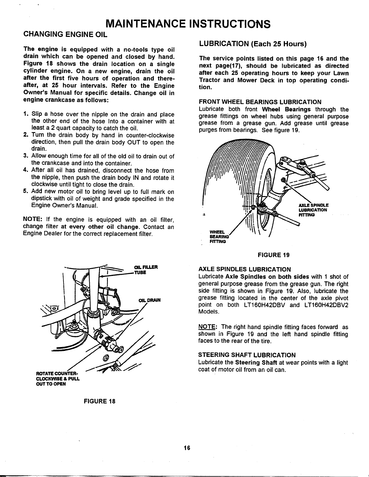
MAINTENANCE INSTRUCTIONS
CHANGING ENGINE OIL
The engine is equipped with a no-tools type oil
drain which can be opened and closed by hand.
Figure 18 shows the drain
cylinder engine. On a new
after the first five hours of
after, at 25 hour intervals.
Owner's Manual for specific
engine crankcase as follows:
1. Slip a hose over the nipple on the drain and place
the other end of the hose Into a container with at
least a 2 quart capacity to catch the oil.
2. Turn the drain body by hand in counter-clockwise
direction, then pull the drain body OUT to open the
drain.
3. Allow enough time for all of the old oil to drain out of
the crankcase and into the container.
4. After all oil has drained, disconnect the hose from
the nipple, then push the drain body IN and rotate it
clockwise until tight to close the drain.
5. Add new motor oil to bring level up to full mark on
dipstick with oil of weight and grade specified in the
Engine Owner's Manual.
NOTE: If the engine is equipped with an oil filter,
change filter at every other oil change. Contact an
Engine Dealer for the correct replacement filter.
location on a single
engine, drain the oil
operation and there-
Refer to the Engine
details. Change oil in
LUBRICATION (Each 25 Hours)
The service points listed on this page 16 and the
next page(17), should be lubricated as directed
after each 25 operating hours to keep your Lawn
Tractor and Mower Deck in top operating condi-
tion.
FRONT WHEEL BEARINGS LUBRICATION
Lubricate both front Wheel Bearings through the
grease fittings on wheel hubs using general purpose
grease from a grease gun. Add grease until grease
purges from bearings. See figure 19.
AXLE SPINDLE
LUBRICATION
FITTING
WHEEL
FITTING
ROTATECOUNTER-
CLOCKWISE & PULL
OUTTO OPEN
I
FIGURE 18
OIL DRAIN
FIGURE 19
AXLE SPINDLES LUBRICATION
Lubricate Axle Spindles on both sides with 1 shot of
general purpose grease from the grease gun. The right
side fitting is shown in Figure 19. Also, lubricate the
grease fitting located in the center of the axle pivot
point on both LT160H42DBV and LT160H42DBV2
Models.
NOTE: The right hand spindle fitting faces forward as
shown in Figure 19 and the left hand spindle fitting
faces to the rear of the tire.
STEERING SHAFT LUBRICATION
Lubricate the Steering Shaft at wear points with a light
coat of motor oil from an oil can.
16
Page 17
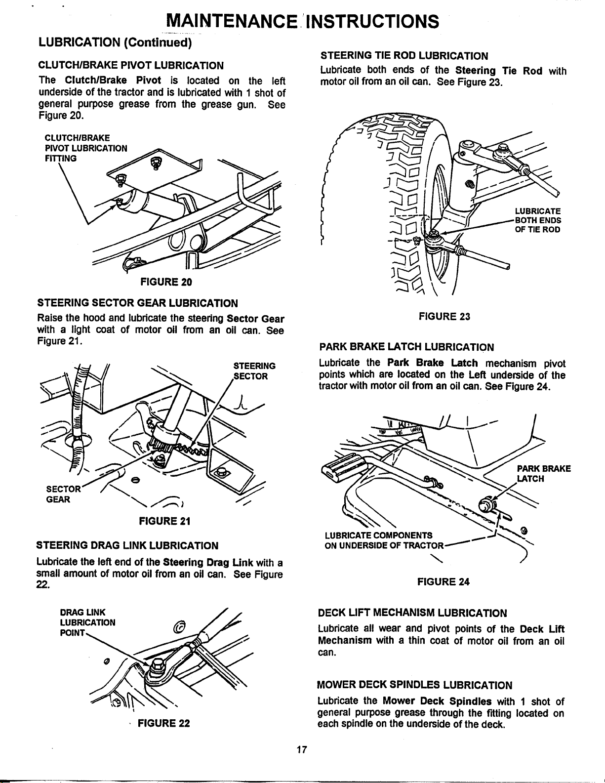
MAINTENANCE INSTRUCTIONS
LUBRICATION (Continued)
CLUTCHIBRAKE PIVOT LUBRICATION
The ClutchlBrake Pivot is located on the left
underside of the tractor and is lubricated with 1 shot of
general purpose grease from the grease gun. See
Figure 20.
CLUTCHIBRAKE
PIVOT LUBRICATION
FITTING
FIGURE 20
STEERING SECTOR GEAR LUBRICATION
Raise the hood and lubricate the steering Sector Gear
with a light coat of motor oil from an oil can. See
Figure 21.
STEERING TIE ROD LUBRICATION
Lubricate both ends of the Steering Tie Rod with
motor oil from an oil can. See Figure 23.
FIGURE 23
PARK BRAKE LATCH LUBRICATION
STEERING
.SECTOR
FIGURE 21
STEERING DRAG LINK LUBRICATION
Lubricate the left end of the Steering Drag Link with a
small amount of motor oil from an oil can. See Figure
22.
DRAG LINK / /
LUBRICATION /_ / _"
Lubricate the Park Brake Latch mechanism pivot
points which are located on the Left underside of the
tractor with motor oil from an oil can. See Figure 24.
PARK BRAKE
LATCH
LUBRICATE COMPONENTS
ON
FIGURE 24
DECK LIFT MECHANISM LUBRICATION
Lubricate all wear and pivot points of the Deck Lift
Mechanism with a thin coat of motor oil from an oil
can.
FIGURE 22
MOWER DECK SPINDLES LUBRICATION
Lubricate the Mower Deck Spindles with 1 shot of
general purpose grease through the fitting located on
each spindle on the underside of the deck.
17
Page 18
................. MAINTENANCE
SERVICE
The engine components listed on this page should
be serviced on a regular basis to keep it in top
working condition. Refer to the "SERVICE
SCHEDULE" on page 13 of this manual for the
recommended intervals. Refer to the Engine
Owner's Manual for specific instructions.
ENGINE PRE-CLEANER
The engine pre-cleaner should be removed and
cleaned every 25 operating hours. See Figure 25 and
25A. Refer to the Engine Owner's Manual for specific
cleaning instructions.
ENGINE AIR CLEANER
The engine air cleaner element should be cleaned each
time the pre-cleaner is serviced and should be replaced
every 100 operating hours. See Figure 25 and 25A.
Refer to the Engine Owner's Manual for specific details
_---_'_-_- "_,,_ COVER RETAINING KNOB
J
INSTRUCTIONS I
• i
SPARK I
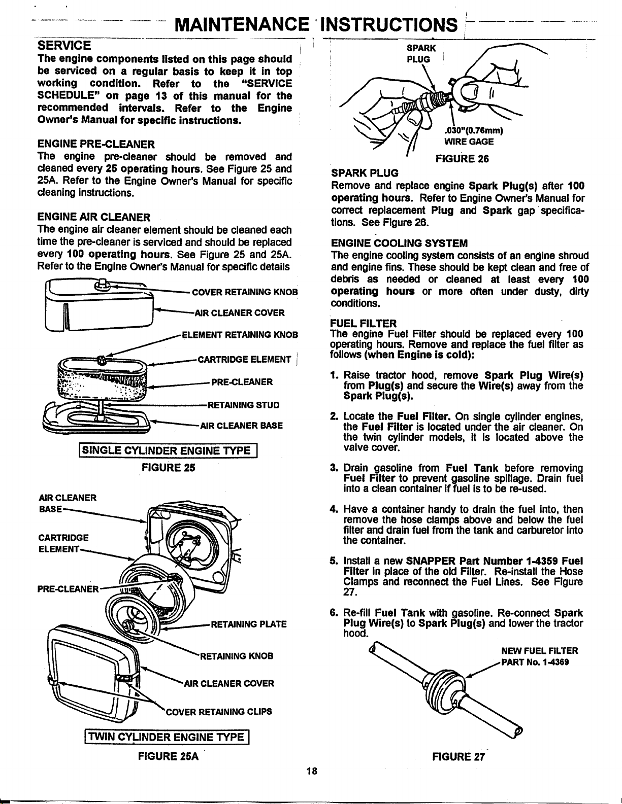
PLUG
\
.030"(0.76mm)
WIRE GAGE
FIGURE 26
SPARK PLUG
Remove and replace engine Spark Plug(s) after 100
operating hours. Refer to Engine Owner's Manual for
correct replacement Plug and Spark gap specifica-
tions. See Figure 26.
ENGINE COOLING SYSTEM
The engine cooling system consists of an engine shroud
and engine fins. These should be kept clean and free of
debds as needed or cleaned at least every 100
operating hours or more often under dusty, dirty
conditions.
L_ _=""----AIR CLEANER COVER
ELEMENT RETAININGKNOB
IDGE ELEMENT I
RETAINING STUD
AIR CLEANER BASE
ISINGLE CYLINDER ENGINE TYPE I
FIGURE 25
AIR CLEANER
CARTRIDGE
NG PLATE
FUEL FILTER
The engine Fuel Filter should be replaced every 100
operating hours. Remove and replace the fuel filter as
follows (when Engine is cold):
1. Raise tractor hood, remove Spark Plug Wire(s)
from Plug(s) and secure the Wire(s) away from the
Spark Plug(s).
.
Locate the Fuel Filter. On single cylinder engines,
the Fuel Filter is located under the air cleaner. On
the twin cylinder models, it is located above the
valve cover.
3. Drain gasoline from Fuel Tank before removing
Fuel Filter to prevent gasoline spillage. Drain fuel
into a clean container if fuel is to be re-used.
=
Have a container handy to drain the fuel into, then
remove the hose clamps above and below the fuel
filter and drain fuel from the tank and carburetor into
the container.
e
Install a new SNAPPER Part Number 1-4359 Fuel
Filter in place of the old Filter. Re-install the Hose
Clamps and reconnect the Fuel Lines. See Figure
27.
.
Re-fill Fuel Tank with gasoline. Re-connect Spark
Plug Wire(s) to Spark Plug(s) and lower the tractor
hood.
RETAINING KNOB
"AIRCLEANER COVER
RETAINING CLIPS
ITWINCYLINDERENGINETYPEI
FIGURE 25A
FIGURE 27-
18
Page 19
MAINTENANCE INSTRUCTIONS
BATTERY SERVICE
The battery should be checked and serviced every
25 hours of operation as follows:
Tilt Operator's Seat forward and remove the two
adjusting knobs then lift the seat assembly off tractor
frame and move it forward out of the way. Be careful
not to disconnect wires from seat switches. See Figure
28.
REdNSTALL
BATTERY
PER DECAL
FILL
\
CLEAN TERMINALS,
CABLES, BOLTS &
NUTS BEFORE
RE4NSTALLING POSITIVE(_
BATTERY
(RED)
GREASE NEGATIVE (-)
TERMINALS TERMINAL
AFTER (BLACK)
CONNECTING
FIGURE 28
CHECKING BATTERY ELECTROLYTE
WARNING
The Electrolyte (Acid) produces a highly explosive
gas. Keep all Sparks, Flame and Fire away from the
area when charging battery or when handling
electrolyte or battery. Electrolyte (Acid) is a highly
corrosive liquid. Wear eye protection. In case of
eye or skin contact with Electrolyte (Acid), wash
all affective areas of the body immediately with
water.
Clean top of battery, disconnect battery positive cable
to prevent arching, then carefully remove the battery
cell covers.
Visually check electrolyte level in each cell. Level
should be 3116"above cell plates up to the fill rings.
Using distilled water, fill cells as needed to bring level
up to, but not over, the fill rings. See Figure 29.
Replace cell covers and reconnect the positive cable if
disconnected earlier.
FIGURE 29
BATTERY CHARGING PROCEDURE
The engine is equipped with a flywheel altemator to
charge battery. If the tractor is not run regularly,
connect battery to a charger monthly to maintain
charge. If low, battery liquid could freeze at zero
degree temperatures causing cracking of the battery
case. To prevent freezing, keep the charge up or
remove the battery from the tractor and store battery in
warm, well ventilated area during the off season. Store
on wooden surface, not on cement floor.
le
Always remove the Negative (.) cable first to
prevent arching and remove Positive (+) cable last.
m
To charge, connect a constant current charger
(not trickle type) and follow instructions furnished
with the charger.
.
If time allows, slow charge at 1 amp for 10 hours, or
as an alternate, fast charge at not more than 2.5
amps for four hours. Observe ALL Precautions
while charging.
=
Install Positive (+) cable first and install Negative(-)
cable last. Apply a small amount of grease over the
terminals to prevent corrosion.
1
Re-install seat assembly over battery and secure in
position with adjusting knobs. Leave knobs loose
until the seat is adjusted, then tighten.
ACTIVATING A NEW BATTERY
Activating a new Battery with Electrolyte (Acid) will
bring it up to 80 % of full charge state. It must be
brought up to full charge, which means 20% additional
charge is needed. Charge a new Battery for 2 hours on
a slow charge rate of I Amp to bring it up to full charge
before installing it in tractor.
19
Page 20
.............. MAINTENANCE
MOWER DECK SERVICE
MOWER DECK REMOVAL (42" Mower Deck)
The Mower Deck will have to be removed to replace
blades or deck belts as described on following
pages. Remove deck as follows:
1. Place tractor on a firm, level surface such as a
driveway or garage floor and set the park brake.
2. Tum engine "OFF" and remove key. Raise hood and
remove spark plug wire(s) from spark plug(s).
Secure wire(s) away from plug(s). See Figure 30.
REMOVE WIRE BOOT
FROM SPARK PLUG
SPARK
PLUG
INSTRUCTIONS -.....................
a=
6. Disconnect the Deck Front Lift Cable by removing
the Hairpin and Washer first. See Figure 32.
WASHER
FRONT
UFT
CABLE
CLEVIS UFT
PIN ARM
FIGURE 32
So
Hold front of Deck up and remove Clevis Pin from
Front Lift Arm, then lower the front of the Deck to
the ground.
FRONT
ISINGLE CYLINDER ENGINE SHOWN I
FIGURE 30
3. Lower the Deck to lowest setting by pushing lock
button in on lift lever, then moving lever full forward.
4. Remove both Hairpins from the Front Deck
Hanger Rod. See Figure 31.
RIGHT
SIDE
SHOWN_
FRONT
FRONT DECK
FRONT
LIFT
ARM
HAIRPIN
a
Make note of hole used in sector plates so same
holes are used during re-assembly. See Figure 33.
Remove hairpins and fiat washers from rear deck
hanger bracket on both sides of tractor.
u
Slide both sector plates off of rear deck hanger
brackets. See Figure 33.
SECTOR
PLATES
REMOVE
&WASHER FROM
BOTH SECTOR PLATES'
FIGURE 33
9. Slide deck forward to allow idler spring to release
tension. See Figures 40 and 42 on page 22.
10. Remove deck drive belt from the electric clutch.
11. Pull deck out from under tractor from right hand side.
12. Reverse this procedure to reinstall mower deck.
• FIGURE 31
(48" DECK REMOVAL INFO ON NEXT PAGE)
20
Page 21
MAINTENANCE INSTRUCTIONS
48" MOWER DECK REMOVAL
,._ /.7_,\_. ) / / HAIRPIN&
Follow steps 1 and 2 (42" Mower
Deck Removal on previous page20),
then lower the deck onto the gage wheels
prior to disconnecting the front and rear lift arms.
A. Disconnect the front lift arm first by
removing the hairpin, washer, and clevis pin. ,, _., _
B,
After disconnecting front lift arm, remove _ , _ _,.
,... .,;./" sW=VSL-.-......__ \_.,_ IJo'
ol • ._
I " ,. HAIRPIN &
.,_!,,.. _-_" "\ WASHER ] BRACKL=I'.,,.,_ .._
"\ ""x ""_ ;_ UFTARM
hairpins and washers from rear deck swivels, then _-_ "-, \cumin
slide each swivel out from rear deck brackets. ..,, _..._ PiN
NOTE: It may be necessary to slightly prop up the
front of the deck when removing clevis pin to take
pressure off of front lift arm. The same procedure
should be used when removing swivels from the rear
deck brackets.
4. Install sharpened or new Blades, (SNAPPER Part
WEAR LIMITS - STANDARD BLADES
Mower Blades should be checked for excessive wear
and damage before each use. See Figure 34 for Blade
No. 2-6691) and secure each with the Cone Wash-
er and Mounting Bolt. Torque Mounting Bolts to
40 ft. Ibs.
wear conditions on a standard Blade.
5. If Blade is in good condition but cutting edge is dull,
NOTCH _'_
FORMING-._ _ _',,_ _J
sharpen at a 25 degree angle as shown in Figure 36.
SILHOUETTE
OF 48" DECK
sW=VEL ;,; .;_" ?,
_._'..,'._..._
(c)DANaE.OUSCONOmON,
DONOT USE ON MOWER!
FIGURE 34
Blades should be kept sharp at all times. Sharpen
Blades ONLY if good condition. Replace if worn or
damaged. Install new Air Lifters on Blades if so
equipped when the Blades are being replaced.
Never use a blade that shows signs of excessive
wear or damage. Refer to Figure 34 for STANDARD
STANDARD MOWER BLADES - REMOVAL
AND REPLACEMENT
1. Remove the Mower Deck from Tractor following
instructions on page 20 under, "MOWER DECK
REMOVAL".
2. Carefully position the Deck to access Blades and
inspect both Blades for signs of damage or wear.
3. Remove Blade(s) Mounting Bolt(s) and Cone
Washer(s) from each Blade and remove Blades to
sharpen or replace as needed. See Figure 35.
WARNING
blade wear limits.
/MOUNTING BOLT
,a_.."v (TORQUE TO 40
FOOT POUN0S)
FIGURE 35
SHARPENING STANDARD BLADE(S)
Blades should be kept sharp at all times. When the
Blade(s) are dull, cut grass will be ragged and lawn will
usually turn brown. Sharpen standard Blades as
follows:
1. Sharpen the 2-1/2" cutting edges on standard
mower Blades at a 25° angle. See Figure 36.
2. Tighten the Blade Mounting Bolt to torque
specified as shown in Figure 35.
BLADE TIP /
1/2"
/
FIGURE 36
21
Page 22
• t
MAINTENANCE
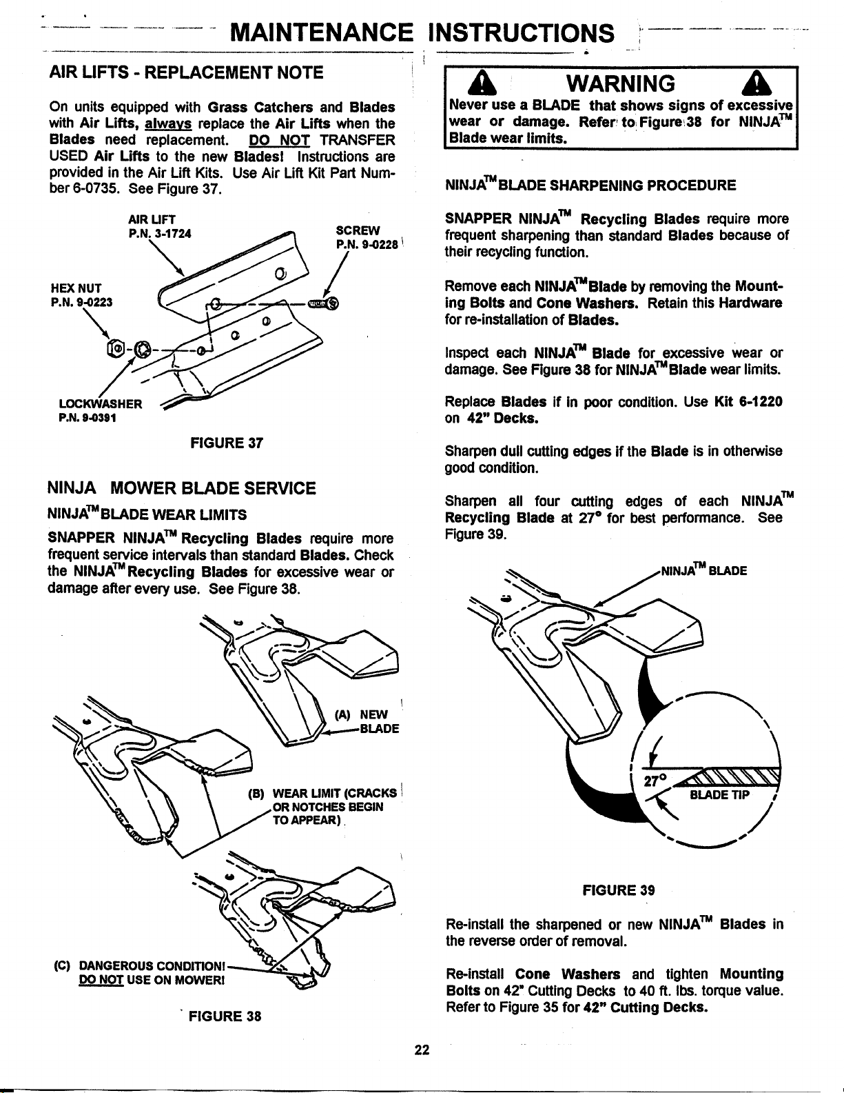
AIR LIFTS - REPLACEMENT NOTE
INSTRUCTIONS !
On units equipped with Grass Catchers and Blades
with Air Lifts, alwavs replace the Air Lifts when the
Blades need replacement. DO NOT TRANSFER
USED Air Lifts to the new Bladesl Instructions are
provided in the Air Lift Kits. Use Air Lift Kit Part Num-
ber 6-0735. See Figure 37.
AIR UFT
P,N, 9-0391
FIGURE 37
NINJA MOWER BLADE SERVICE
NINJA_IBLADE WEAR LIMITS
SNAPPER NINJATM Recycling Blades require more
frequent service intervals than standard Blades. Check
the NINJATM Recycling Blades for excessive wear or
damage after every use. See Figure 38.
I WARNING I
I Never use a BLADE that, shows signs of e.....ivTue
IwearBladeOrweardamage.limits.Referr to Figure_38 for N!NJA I
NINJATMBLADE SHARPENING PROCEDURE
SNAPPER NINJA TM Recycling Blades require more
frequent sharpening than standard Blades because of
their recycling function.
Remove each NINJA_Blade by removing the Mount-
ing Bolts and Cone Washers. Retain this Hardware
for re-installation of Blades.
Inspect each NINJA TM Blade for excessive wear or
damage. See Figure 38 for NINJATMBlade wear limits.
Replace Blades if in poor condition. Use Kit 6-1220
on 42" Decks.
Sharpen dull cutting edges if the Blade is in otherwise
good condition.
Sharpen all four cutting edges of each NINJATM
Recycling Blade at 27° for best performance. See
Figure 39.
BLADE
(C) DANGEROUS
USE ON MOWER!
FIGURE 38
FIGURE 39
Re-install the sharpened or new NINJA TM Blades in
the reverse order of removal.
Re-install Cone Washers and tighten Mounting
Bolts on 42" Cutting Decks to 40 ft. Ibs. torque value.
Refer to Figure 35 for 42" Cutting Decks.
22
Page 23
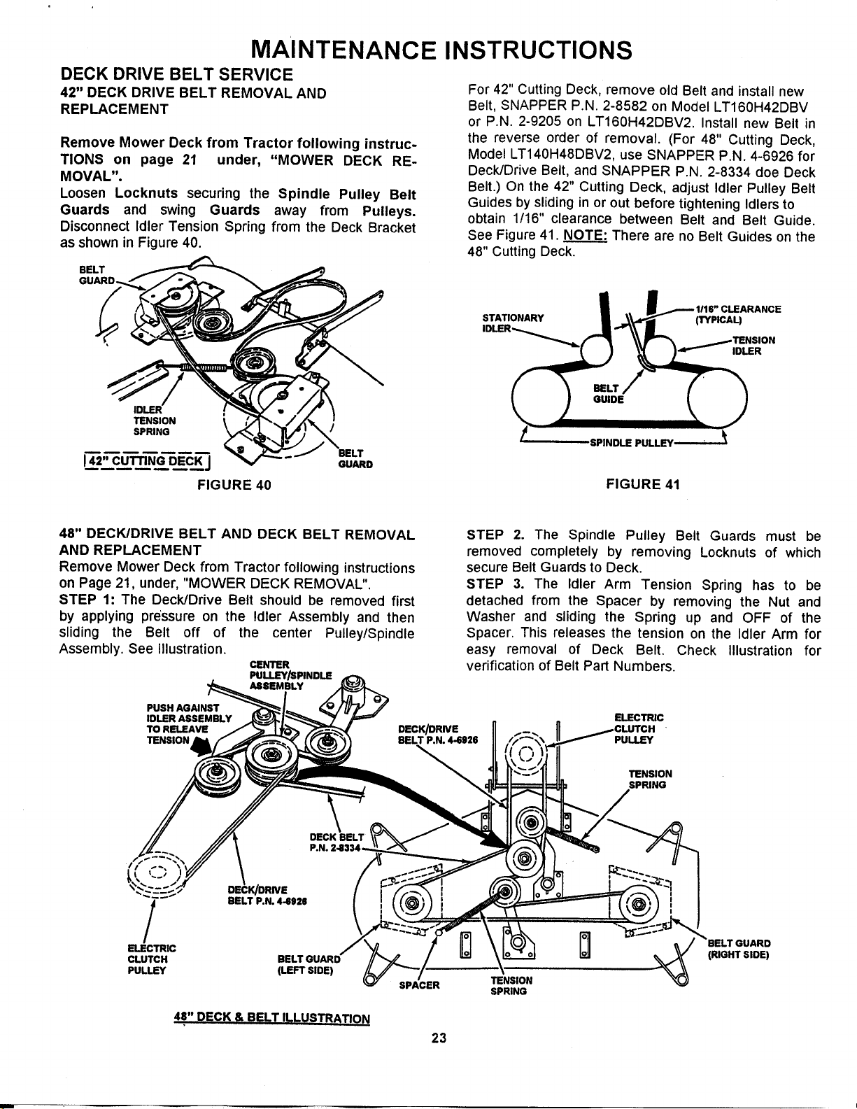
MAINTENANCE INSTRUCTIONS
DECK DRIVE BELT SERVICE
42" DECK DRIVE BELT REMOVAL AND
REPLACEMENT
Remove Mower Deck from Tractor following instruc-
TIONS on page 21 under, "MOWER DECK RE-
MOVAL".
Loosen Locknuts securing the Spindle Pulley Belt
Guards and swing Guards away from Pulleys.
Disconnect Idler Tension Spring from the Deck Bracket
as shown in Figure 40.
BELT
For 42" Cutting Deck, remove old Belt and install new
Belt, SNAPPER P.N. 2-8582 on Model LT160H42DBV
or P.N. 2-9205 on LT160H42DBV2. Install new Belt in
the reverse order of removal. (For 48" Cutting Deck,
Model LT140H48DBV2, use SNAPPER P.N. 4-6926 for
Deck/Drive Belt, and SNAPPER P.N. 2-8334 doe Deck
Belt.) On the 42" Cutting Deck, adjust Idler Pulley Belt
Guides by sliding in or out before tightening Idlers to
obtain 1/16" clearance between Belt and Belt Guide.
See Figure 41. NOTE: There are no Belt Guides on the
48" Cutting Deck.
STATIONARY (TYPICAL)
IDLER--_._
_TENSION
"_'_- IDLER
TENSION
SPRING
142"CUTTINGDE._.C_J
/
BELT
GUARD
FIGURE 40
48" DECK/DRIVE BELT AND DECK BELT REMOVAL
AND REPLACEMENT
Remove Mower Deck from Tractor following instructions
on Page 21, under, "MOWER DECK REMOVAL".
STEP 1: The Deck/Drive Belt should be removed first
by applying pressure on the Idler Assembly and then
sliding the Belt off of the center Pulley/Spindle
Assembly. See Illustration.
CENTER
PULLEY/SPINDLE
ASSEMBLY
PUSH AGAINST
IDLER ASSEMBLY
TO RELEAVE
TENSION
DECK/DRIVE
BELT P.N. 44926
FIGURE 41
STEP 2. The Spindle Pulley Belt Guards must be
removed completely by removing Locknuts of which
secure Belt Guards to Deck.
STEP 3. The Idler Arm Tension Spring has to be
detached from the Spacer by removing the Nut and
Washer and sliding the Spring up and OFF of the
Spacer. This releases the tension on the Idler Arm for
easy removal of Deck Belt. Check Illustration for
verification of Belt Part Numbers.
ELECTRIC
PULLEY
TENSION
SPRING
/
ELECTRIC
CLUTCH
PULLEY
DECK BELT
P.N.
DECK/DRNE
BELT P.N. 4-6926
(LEFT SIDE)
48" DECK & BELT II_LUSTRATION
SPACER
(RIGHT SLOE)
TENSION
SPRING
23
Page 24

MAINTENANCE INSTRUCTIONS .............................
TRACTION DRIVE BELT SERVICE ...................
Check the Traction Drive Belt for damage and wear after
25 operating hours. The Traction Drive Belt is located
on the underside of the Tractor and spans the Engine
Pulley's top groove to the Transmission Pulley. See Fig-
ure 42. If this Belt shows signs of excessive wear or
damage, replace it as follows:
ENGINE PULLEY TRANSMISSION
TOP GROOVE DRIVE PULLEY
__lll__/ STATIONARY TENSION
DRIVE BELT IDLER IDLER
FIGURE 42
Loosen Mounting Nuts on Traction Drive Belt Idlers just
enough to allow Belt to clear Belt Guides. Remove Trac-
tion Drive Belt from top groove of Engine Pulley. See
Figure 43. Remove Belt from Belt Guide, then pull Belt
back until it can be removed from Transmission Pulley.
TRACTION DRIVE BELT- REPLACEMENT
Place new Traction Drive Belt over Transmission Pulley
and span to Engine Pulley. Place Belt into top groove of
Engine Pulley (groove above Electric Clutch). See Fig-
ure 43. Route Belt through Stationary and Tension
Idlers. NOTE: When installing a new Belt, make certain
the Stationary Idler is mounted in the hole closest to the
left hand side ofthe Tractor. See Figure 45.
STATIONARY
IDLER BRACKET _ . /| ,, -.
TRACTION DRIVE BELT REMOVAL
NOTE: Although it is possible to replace the Traction
Drive Belt without removing the Mower Deck, Deck re-
moval will make Belt replacement easier. Remove Mow-
er from Tractor following: instructions on page 20 under
"MOWER DECK REMOVAL". Depress Clutch/Brake
Pedal and set Parking Brake. Roll Mower Drive Belt out
of groove in the Electric Clutch Pulley and lower Belt for
access to Traction Drive Belt. See Figure 43.
TOP GROOVE OF
ENGINE PULLEY DRIVE BELT
ELECTRIC
CLUTCH
ROLL MOWER
DRIVE BELT OFF
OF ELECTRIC
CLUTCH PULLEY
FIGURE 43
j_/ll BELT" _ _ _ I._ /
STATIONARY I
IDLER TRANSMISSION
PULLEY
BELT GUIDE
(_ IDLER
I
FIGURE 45
Make certain Belt is within Belt Guides and that Idlers
turn freely. Re-connect tension Idler Spring to Tractor
Frame. See Figure 44. Re-install Mower Deck (if re-
moved) in reverse order of removal. Refer to page 20.
MOUNTING
BELT GUIDE /
1 1 _ _ HT FOR
BRACKET
Disconnect the Idler Pulley tension Spring from Tractor
Frame. See Figure 44.
OF TRACTOR
FRAME
IDLER TENSION
SPRING CONNECTION
TO FRAME
FIGURE 44
MOUNTING BOLT
LVIEWED FROM UNDERNEATH TRACTOR ]
FIGURE 46
24
Page 25

MAINTENANCE INSTRUCTIONS
TRACTION DRIVE BELT ADJUSTMENT,
If a gradual loss of traction is noticed, it may be neces-
sary to adjust the Traction Drive Belt tension by reposi-
tioning the Stationary Idler as follows:
NOTE the position of Belt Guide on Stationary Idler and
make certain it remains the same after moving Idler. Re-
move the Traction Drive Belt Stationary Idler Mounting
Bolt. See Figure 46.
Move the Stationary Idler one hole towards right side of
Tractor for more Belt tension. NOTE: Right and Left
sides indicated in Figures 46 and 47 are as viewed from
Operator's position on Seat.
USE RIGHT SIDE
_,_._ HOLE FOR MORE
LEADING
BLADE
TIP
BLADE
DISCHARGE
;IDE
TRAILING
BLADE
FIGURE 48
TENSION
LESS
MOUNTING _
BRACKET
MOUNTING
= _BELT GUIDE(MAKE
I
--TENSION
CERTAIN BELT GUIDE'
ORIENTATIONIS
MAINTAINE_
IDLER
BOLT I
FIGURE 47
Secure Stationary Idler by tightening the Mounting Bolt.
When properly adjusted, the Traction Drive Belt will not
rotate with the Park Brake set and Engine running.
TIRES and PRESSURE
It is a good idea to check Tire Pressure before each
mowing job. Uneven Tire Pressure can cause poor cutt-
ing patterns, especially uneven cutting from Side-To-
Side. Keep pressure in Front Tires at 12 psi and Rear
Tires at 10 psi (pounds per square inch) at all times!
Remove Hairpins and Washers securing rear of Deck to
Sector Plates. See Figure 49. Slide Sector Plates off of
Pins and carefully lower Deck onto Angle Iron or similar
object. Measure distance from Blade Tip to floor on
each side of deck. Blade Tips should be within 118"of
each other for the Deck to be considered level. If this
differs more than 1/8", adjust as follows:
PLATES
REMOVE HAIRPINS
BOTH SECTOR PLATES
& WASHERS FROM
FIGURE 49
SIDE TO SIDE LEVEL ADJUSTMENT (42"
CUTTING DECK)
Loosen front Lift Arm Pivot Bolt on front of right side rail.
See Figure 50. Turn Eccentric "UP" or "DOWN" as re-
quired to level Deck, then securely tighten the Eccentric
Shoulder Bolt and the Pivot Bolt.
LOOSEN O
PIVOT BOLT
DECK LEVEL ADJUSTMENTS
If the mowed path is uneven from Side-To-Side and the
Tires are properly inflated, check Mower Deck for correct
Side-To-Side levelness and adjust if needed.
SIDE TO SIDE LEVEL CHECK
Move Tractor to a firm, level surface, turn Blades and
Engine OFF, then raise Hood and remove Spark Plug
Wire(s) from Spark Plug(s) and secure Wire(s) away
from Plug(s). Rotate both Blades until Blade Tips are at
each side of Deck as shown in Figure 48. Place a piece
of Angle Iron or similar object under center rear of Deck.
LOOSEN
BOLT _
Z
TURN ECCENTRIC
AS REQUIRED
FIGURE 50
Place Sector Plates back onto rear Lift using hole that
most closely lines up with Pin. Secure with Washer and
Hairpins.
25
Page 26

MAINTENANCE INSTRUCTIONS
MOWER DECK ADJUSTMENT (LEVELNESS)
Side To Side Level (48" Cutting Deck)
Before making deck leveling adjustments, check the tire
pressure. Add or release air as needed to bring pressure
to 10 PSI in front and 10 PSI in rear tires. If tires are
property inflated and mowing ts still uneven, adjust side-
to-side deck levelness first as follows:
1. Place machine on a smooth level surface.
2. Rotate outside blades so tips are pointed to the
sides of deck. See Figure 51. Measure the
distance from blade tips to floor. If the
measurement is within 1/8" from side-to-side, the
deck levelness is satisfactory. If the difference
from side-to-side is greater than 1/8", continue to
next step for adjustment.
3. Place a 2 x 4 piece of wood under the front
middle portion of deck. Place one 2 x 4 piece of
wood under the rear of deck on both sides behind
the two outside blades. See Figure 51.
4. Lower deck down to rest on the three 2 x 4
pieces of wood. Make sure there is no deck
tension on the lift rods supporting the deck.
5. Loosen the bolt and nut that secures the front lift
arm weldment to the front lift arm. See Inset.
6. Remove both hair pins and washers from swivel
located on rear lift rods and pull rod out of lift
brackets.
7. Rotate swivels on both sides up or down to
achieve the proper levelness. See Figure 51A.
8. Reinstall swivel into deck bracket. Reinstall
washers and hair pins.
9. Tighten nut and bolt on front lift arm securely.
4.3.4. MOWER DECK ADJUSTMENT (LEVELNESS)
Front to Rear Deck Pitch (48" Deck)
Before making deck leveling adjustments, check the
tire pressure. Add or release air as needed to bring
pressure to 10 PSI in front and 10 PSI in rear tires. If
tires are properly inflated and mowing is still uneven,
check side-to-side deck levelness first then proceed
to front to rear adjustment. Adjust front to rear deck
levelness as follows:
1. Place machine on a smooth level surface.
2. Rotate outside blades so tips are pointed to the
front and rear of deck. Measure the distance
from blade tips to floor. The distance should be
the same. If the rear blade tip is higher lower
than the front, proceed to Step 4 for adjustment.
3. Remove the hair pin & washer from swivel
located on front lift rod. Remove swivel/lift rod
from hanger bracket.
4. Rotate swivel up or down to achieve the proper
levelness.
5. Reinsert swivel/lift rod into hanger bracket.
Reinstall washer & hair pin. See Figure 51A.
TOP VIEW OF DECK
REMOVE WASHER & HAIR PIN
& ROTATE SWIVEL UP (
_'_ HANGER
A
BRACKET
FRONT
"-, LIFT
x\
\ ROD__ -_1_
% %
'%% %,%,
% % ' _ /!
FRONT OF DECK ""'--_.._. \_;_'/ ..."
, FIGURE 51A
REAR UFT FIGURE 51
REMOVE WASHER & HAIR PIN.
& ROTATE SWIVEL UP OR DOWN
" "-_,.... "_ UFT
LIFT
BRACKE'r
"-.-........ -.....'__\ /.t ...j /
.... -t\_--/ I--- /
SWIVEL, , s_/
'
t I • r
26
Q
PLACE THREE 2 x 4 UNDER
FRONT ANDREAR OF DECK
FRONT
s _,s (\ $7
' LOOSEN
NUT
TOP VIEW OF DECK
FRONT
UFT
ARM
WELDMENT
Page 27

MAINTENANCE INSTRUCTIONS
FRONT TO REAR LEVEL ADJUSTMENT
at SECTOR PLATES
Remove Hair-Pins and Washers securing Sector
Plates to rear Lift Arms. See Figure 52.
Move Sector Plates the same number of holes as
required to raise or lower the Deck.
The Deck should be set 1/4" lower at the rear than at
the front.
If the Sector Plates are in the lowest possible setting
and the correct front to rear level is not obtained, adjust
according to section about front Lift Rods.
PLATES
Remove Hair-Pin and Washer securing FRONT Lift
Cable to FRONT Lift Arm. See Figure 53.
HAIR4PIN
PIN
CLEVIS
FRONT
LIFT CABLE
JAM-NUT
FIGURE 53
Remove the front Lift Cable and carefully lower front
of Deck onto the 2" block.
LOWEST
"-" HIGHEST
DECK SETTING
REMOVE
& WASHER
SETTING
FIGURE 52
FRONT TO REAR LEVEL ADJUSTMENT
at FRONT LIFT CABLE
If the Sector Plates are in their lowest setting and
proper level cannot be obtained, adjust the front
Lift Rod as follows:
Move Deck Lift Lever to the highest position.
Place a 2" wooden block or similar object under front
center of Deck.
Place a 3" wooden block or similar object under rear
center of Deck.
Turn front Lift Cable after loosening Jam-Nut until it
can be re-installed to Lift Arm without lifting Deck off
of the blocks.
Secure Lift Rod to Lift Arm with Washer and Hair-
Pin.
Place Sector Plates onto rear Hanger Brackets and
secure with Washers and Hair-Pins.
Raise Deck and remove wooden blocks or similar ob-
jects.
Repeat steps for Front-To-Rear level adjustment. Refer
to FRONT TO REAR LEVEL at SECTOR PLATES
section.
Remove Hair-Pins and Washers securing Sector
Plates (See Figure 52). Lower rear of Deck onto the 3"
block.
27
Page 28

...... MAINTENANCE
INSTRUCTIONS
SHIFTER ADJUSTMENT
If movement of Tractor does not correspond with
the selected speed or Shift Quadrant, adjust the
Speed Control Lever as follows:
With Engine running, drive Tractor and move Shift
Lever to locate NEUTRAL.
Turn Engine "OFF".
Locate Speed Control Lever Mount inside right rear
tire, See Figure 54.
SPEED
CONTROL
LEVER
I STEERING ADJUSTMENT
Should excessive "Play" be noted in the steedng,
adjust at the Steering Sector as follows:
Turn Engine "OFF" and raise Tractor Hood.
From left side of Tractor, locate the Steering Sector
below Fuel Tank. See Figure 56.
Loosen the Eccentric Mounting Nut and rotate the
Eccentric clockwise until Steering "Play" is reduced.
Tighten Eccentric Mounting Nut and lower Hood into
operating position.
STEERING
SHAFT
FUEL TANK
FIGURE 54
Move the Speed Control Lever until it is in direct
relation to the Neutral "N" position on Quadrant. See
Figure 55.
Tighten Mounting Nuts and test Shifter operation.
SPEED
CONTROL
LEVER
MOVE TO I
NEUTRAL (N)
POSITION
ECCENTRIC ECCENTRIC
CLOCKWISE TO MOUNTING /
LESSEN FREE-PLAY HEX-NUT
FIGURE 56
• FIGURE 55
.... 28 .........
Page 29

.....................................MAINTENANCE
INSTRUCTIONS
WHEEL BRAKE ADJUSTMENT
When the Wheel Brake is properly adjusted, the rear
Wheels will lock and skid when the Tractor is pushed
forward with the Parking Brake set. Make sure the
Engine is STOPPED and Key is removed before
testing.
Adjust Brake if rear Wheels turn and DO NOT lock
with Parking Brake set as follows:
Turn Engine "OFF" and remove Key.
Raise Hood, remove Spark Plug Wire(s) from Spark
Plug(s) and secure Wire(s) away from Plug(s).
Locate Brake Adjustment on right side of Tractor in
front of and inside dght rear Wheel. See Figure 63.
Turn Nut clockwise to increase Braking action or
counter-clockwise to decrease Braking action. See
Figure 57.
Replace Spark Plug Wire(s), start Engine and test
Brake.
Continue adjustment as described above until proper
adjustment is achieved.
BLADE BRAKE NOTE
In addition to engaging the Blade Belt when the
Blades are switched ON by pulling the PTO Switch
out to "ON", the Electric Clutch functions to Brake
and STOP the Blades from rotating when the PTO
Switch is pushed in to the "OFF" position. The
Electric Clutch is non-adjustable. If it fails to engage
the Blade Belt or fails to STOP Blade rotation, contact
an Authorized SNAPPER Dealer to correct.
ELECTRICAL SYSTEM
20 AMP FUSE PROTECTION
A 20 Amp, Automotive Type Fuse is used to protect
the Electrical Circuit. See Figure 58 for the location
of this Fuse.
If the Engine fails to crank and the Battery is fully
charged, a blown Fuse could be the cause.
Pull the Fuse out of the holder and check to see if the
metal Fuse Wire is broken. If the Wire is intact, re-
install the Fuse in the holder and check for some other
cause.
\
LOOSEN
(COUNTER-
FIGURE 57
TIGHTEN
BRAKE
ADJUSTING
NUT
WARNING
Proper wheel brake and blade brake function is very
important. DO NOT operate machine if brake(s) are
not functioning properly.
If the Fuse is blown, install a new 20 Amp Fuse,
(SNAPPER Part Number 2-3653) in the holder.
FUEL
CON:
- FUSE HOLDER
\
20 AMP FUSE
FIGURE 58
29
Page 30

ELECTRICAL SYSTEM,_
BRAKE swrr_t
(SHOWN DISENGAGED)
BLACK
SWITCH CLUTCH LOAD'
OFF)
GREEN
PURPLE
STARTER
ENGINE
ANTI-AFTER
SOLENOID
,,d=.,,--IGNITIONGROUND
ALTERNATOR
BLA
RED
RED
GREEN WHITE
-'='. BLUE
PURPLE
RED
ILLUSTRATED DIAGRAM for
Model LT160H42DBV
NC
YELLOW
RED
UGHT SWITCH
KEY_
PINK
/
SCHEMATIC WIRING DIAGRAM
for MODEL LT160H42DBV
TO RELAY
T
ENGINE
GROUND
ANTI.AFTF.R FIRE
SOLENOID GROUND
TO ENGINE
ALTERNATOR
TO ENGINE
STARTER
GREEN
TO
ELECTRIC
CLUTCH
TO
TO PEDAL
SWITCH
FIGURE 69
SWITCH
TO
STARTER
SOLENOID
TO
8ATI'ERY
SOLENOIO
20AMP
RISE
TO
_-- IGNITION
SWITCH
'_TO PTO SWITCH
30
Page 31

,ELECTRICAL
BRAKE SWITCH
(SHOWN DISENGAGED)
SYSTEM,
Pro SWITCH
BLACK (SHOWN OFF)
CLUTCH LOAD
GREEN
ENC,
SENSOR
PURPLE
STARTER
r
PURPLE
[
I- HCi RED
ANTI-AFTER .---
RRE SOLENOID'.
,_,,IGNITION GROUND
RED
BLACK
RED
SOLENOID
WHITE
RELAY
NC
YELLOW
RED
-- -I-
GREEN WHITE
BATTERY .-_ 8LUE
PURPLE
OIL PRESSURE
uaN,y
SCHEMATIC WIRING DIAGRAM for MODELS LT160H42DBV2 & LT180H48DBV2
LIGHT
ILLUSTRATED DIAGRAM for MODELS
LT160H42DBV2 & LT180H48DBV2
TO ANTI-
AF'r-P.RRRE
SOLENOID
TO
IGNITION
GROUND
TO 1
ALTERNATOR
TO OIL
PRESSURE
GROUND
RED
TO
ELECTRIC
CLUTCH
TO PEDAL
SWITCH
FUSE
TO RELAY
TO
SWITCH
TO STARTER
OLENOID
TO BATTERY
SOLENOID
TO COIL
,SOLENOID
TO
SWITCH
TO ENGINE'
STARTER
i
GREEN
TO
FIGURE 60
31
SWITCH
ro PTO SWITCH
+o/
INDICATOR
UGHTS
Page 32

i i i
i
SNAPPER
3 YEAR LIMITED WARRANTY
For three (3) years from purchase date for the original purchaser's residential, non-commercial use, SNAPPER, through
any SNAPPER dealer will replace, free of charge (except for taxes where applicable), any part or parts found upon
examination by the factory at McDonough, Georgia, to be defective in material or workmanship or both.
For ninety (90) days from purchase date for the original purchaser's commercial, rental, or other non-residential use,
SNAPPER, through any SNAPPER dealer will replace, free of charge, any part or parts found upon examination by the
factory at McDonough, Georgia, to be defective in material or workmanship or both.
All transportation costs incurred by the purchaser in submitting material to a SNAPPER dealer for replacement under this
!warranty must be paid by the purchaser.
This warranty does not apply to engines and their components, hydro transmissions, gear drive transmissions and
batteries, as these items are warranted separately. This warranty does not apply to parts that have been damaged by
accident, alteration, abuse, improper lubrication, normal wear, or other cause beyond the control of SNAPPER. This
warranty does not cover any machine or component part that has been altered or modified changing safety,
performance, or durability.
There is no other express warranty.
DISCLAIMER OF WARRANTY
Implied warranties, including those of merchantability and fitness for a particular purpose, are limited to three
(3) years from purchase date for the original purchaser's residential or other non-commercial use, and ninety
(90) days from purchase for the original purchaser's commercial, rental or other non-residential use, and to the
extent permitted by law, any and all implied warranties are excluded. This is the exclusive remedy. Liabilities for
consequential damages, under any and all warranties are excluded.
Some states do not allow limitations on how long an implied warranty lasts, or do not allow the exclusion or
limitation of incidental or consequential damages, so the above limitation or exclusion may not apply to you.
This warranty gives you specific legal rights, and you may also have other rights which vary from state to state.
WARNING: THE USE OF REPLACEMENT PARTS OTHER THAN GENUINE SNAPPER PARTS MAY IMPAIR THE
SAFETY OF SNAPPER PRODUCTS AND WILL VOID ANY LIABILITY AND WARRANTY BY SNAPPER
ASSOCIATED WITH THE USE OF SUCH PARTS.
IMPORTANT: Please fill out the attached SNAPPER Product Registration Card immediately and mail to:
Snapper's Product Registration Center, P.O. Box 777, McDonough, Georgia 30253
i
32
Page 33

SERVICE NOTES
Page 34

PRIMARY MAINTENANCE
vs.DIRT#
IIII
an
illustration of
how dirt can
' ; damage your
,engine & how
Snapper uses the best avail-
able engines and components
In their products In order to
provide long, satisfactory
service. However, proper
care is essential In
prolonging engine life. Dirt
is your engine's enemy
number 11
reasonable
maintenance
can protect it!
34
The engine on your Snapper
product spends Its entire life
operating close to the ground at
high speed creating a virtual
storm of dust and dlrtl
Page 35

PRIMARY MAINTENANCE
gulp about 12,000
gallons of air for
every gallon of
used. Because of
Its working environ.
ment, the air available
to your Snapper engine Is "
heavily saturated with air-
borne dirt particles.
g that dirt will
quickly ruin an engine,
manufacturers equip their
engines with extremely
efficient air cleaners to
out the harmful dirt.
As the dirt particles are stopped,
they build up and begin to clog
the outside of the filter. This
reduces the amount of air
available to the engine and causes
an over-rich fuel mixture which re-
sults In the following adverse
effects:
An Improperly serviced, dirt
clogged air cleaner will:
1.
Increase fuel consumption
2.
cause power loss
3. result In hard starting
4. create smoke from unburned
fuel
5. produce carbon build-up ;
Internally
6. foul spark plug electrodes
7. score cylinder walls
8. burn valves
9. wear out the engine pre-
,°
maturely
10. COST YOU MONEY!
Damage caused by a poorly serviced air
cleaner is not covered under the engine
warranties. So, save yourself unnecessary
expenses and undue aggravation by keeping
the air cleaner properly serviced at the Interval.
specified In the engine owner's manual.
It doesn't take long to service an air cleaner.
Follow the specific instructions in the engine
owner's manual for the type filter used. Pre-
vent dirt from falling Into the carburetor Intake
when servicing your air cleaner. Make sure
components are Installed In correct sequence
after servicing to prevent unfiltered air from
entering the engine. Some servicing hints on
several common types are:
35
Page 36

Generally, wash foam-type filters
in a dishwashlng detergent and
water soluUon. RinsE) and wring
dry, then saturate with oil and
squeeze out excess. Failure to
re-oil this type filter will ruin the
engine.
Clean paper elements by tapping
IighUy. Blowing with air will
rupture paper elements.
Use a flashlight to detect clogged
or torn paper elements - replace if
damaged In any way.
PRIMARY MAINTENANCE
Fallura to keep external
surfaces clean not only
presents fire hazards, but
causes overheating and
resulting engine damages
such as:
1. dlstortad valve guldee
2. sticking valves
t° o. 3. scuffed, scored
walls
4. overapeedlng
_) 5. loss of power
6. complete failure of
engine.
Air Is also needed to keep
your engine cool. Dirt, dust
& debris build up to restrict
and clog cooling air Intake
screens and fins. Clean
screens and fins at frequent
Intervals. The engine blower
housing and shrouds should
be removed at least once
each season or more often
l under dry, dusty conditions
for a thorough cleenlng of
fins.
Dirt can also be Introduced
Into an engine In dirty fuel
from a contaminated
contslner. Always use clean
fresh fuel from a clean
container to guard against
dirt, sludge and water
contsmlnatlon.
Be aware that fuel breaks
storage and forms
gummy compounds which
will block carburetor pass-
ages. Never use fuel more
than 3 months old. Drain
tank then run the engine out
of fuel before storing during
the off-season.
An engine must also have proper lubriceUon.
All englnee use some oil On 4-cycle enginee,
CHECK OIL LEVEL BEFORE EACH START-UP.
Wipe area clean around the oll check plug or
dipstick opening to keep dirt from falling Into
the engine when checking the oil Always
check with the machine on a level surface.
On engines with dipstick, keep the level up to,
but not over, the FULL mark. When adding o11,
allow time for all of the oil to flow down the fill
tube to prevent a false full reading when the
level could actually be low and result In engine
damage.
36
Page 37

PRIMARY MAINTENANCE
On 4-cyle engines with an oil level plug,
don't be fooled into thinking the engine has
sufficient lubricating oil if you can see "some"
oil in the opening - the level should always be
brought up to the point of overflowing at the
top of the fill hole.
I
U
On 2-cycle engines, lubrication must be
provided by an exact mixture of gasoline
and 2-cycle air-cooled engine oil. A 2-cycle
engine that Is mistakenly run on straight
gasoline will be ruined In less than 5
minutesl If you keep straight gasoline in
addition to pre-mixed 2-cycle engine fuel,
be sure the containers are clearly marked
to avoid mix-up.
Snapper 2-cycle engines require a 32 to 1
mixture of gasoline and BIA certified TC-W
oll such as Snapper's 2-cycle engine oil
Many of the 2-cycle engine oils on the
market today make fantastic claims, but for
the best performance and long engine life,
always use Snapper 2-cycle o11. Pre-mix
the fuel and always shake the container
before filling the tank.
Change oil at regular Intervals using a a high
quality oll such as Snapper's small engine
formulated 4-cycle engine o11. Refer to the
engine owner's manual for oil details.
STARTING CHECK UST
1. Engine OII
2. Air Cleaner
3. Fuel Tank
4. Choke
5. Primer (on
some engines)
6. Safety Inter-
lock Switches
7. Switch &
Blade Control
8. Spark plug
9. Throttle
control
10. Blade
11. Muffler
• To full level (4-cycle)
• Properly mixed with gas
(2 cycle)
• Clean and properly serviced
• Full fresh clean gasoline
• Fuel valve open
• Cap vent open
• Inline filter clean
• Operating properly
• Used properly
• In proper position
• All wires properly connected
• Switch On
• Blade control properly
positioned on walk mower
• Wire connected
• Good connection
• Start position
• Properly Installed and
torqued
• Sharpened
• Good condition
• Not clogged
• Grass & leaves cleaned away
and follow all safety
Instructions In safety book-
lets and manuals.
Keep In mind that dirt Is your engine's enemy
#1 both Internally and externallyl Internally,
dirt will quickly ruin an engine and externally
It will cause overheating and resulting Internal
Damage caused by Improper lubri-
poor air cleaner service or overheating
due to dirt cannot be covered under warranty.
It only takes a few moments to service the
engine (and equipment) on a routine basis
but the rewards will be a quick starting, re-
sponsive engine that will provide long
satisfactory service with minimum maintenance
cost. The prestart check,st In the next column
and Instructions in your Snapper Operator's
Manual are designated to help you keep your
Snapper In top operating condlUon with
minimum effortl
I I
J
37
Page 38

Safety Instructions & Operator's Manual'for
LAWN TRACTORS
ELECTRIC CLUTCH
SERIES D
J_ WARNI NG: The engine exhaust from this product contains chemicals known to the State J
j==m., of California to cause cancer, birth defects or other reproductive harm. I
COPYRIGHT O 1998
SNAPPER INC,
ALL RIGHTS RESERVED
MANUAL No. 3-5624 (REV. 1, 6/98)
Page 39

Safety Instructions & Operator's Manual for
LAWN TRA CTORS
ELECTRIC CLUTCH
SERIES D
MODELS
LT160H42DBV
L T160H42DB V2
L T180H48DB V2
MODEL NUMBER EXPLANATION
l LT I 160I I
oo ,o T,ON--JI
ENGINE HP
DRIVE SYSTEM TYPE
CUTTING WIDTH
LT- ModelDesiqnation I
160- 16.0HP(EngineHorsePower)
180 - 18.0 HP (Engine Horse Power)
H - Hydrostatic Transmission Drive System
42 - 42" Cutting Width Mower Deck
48 -48" Cutting Width Mower Deck
Thank you for buying a SNAPPER product! Before operating the Lawn Tractor, read and follow the
"IMPORTANT SAFETY INSTRUCTIONS" on pages 2 & 3, all other instructions contained in this manual and the
accompanying booklet "About Power Mower Safety". Lawn mowers and all power equipment can be
potentially dangerous if used improperly. REMEMBER: SAFETY REQUIRES CAREFULL USE IN ACCORDANCE
WITH INSTRUCTIONS AND COMMON SENSE !
COPYRIGHT © 1998
SNAPPER INC.
ALL RIGHTS RESERVED
11421=
ENGINE OPTIONS
ENGINE TYPE
ENGINE MODEL
SERIES DESIGNATION
D - Series Desicjnation
B - Briggs & Stratton Enqine
V - Over Head Valve Type Engine
2 - Twin Cylinder Engine
I
MANUAL No. 3.5624 (REV. 1, 6/98)
Page 40

IMPORTANT SAFETY INSTRUCTIONS
WARNING: This powerful cutting machine is capable of amputating hands and feet and can throw objects that
can cause injury and damagel Failure to comply with the following SAFETY instructions could result in
serious injury or death to the operator or other persons. The owner of the machine must understand these
instructions and must allow only persons who understand these instructions to operate machine. Each
person operating the machine must be of sound mind and body and must not be under the influence of any
substance which might impair vision, dexterity or judgment. If you have any questions pertaining to your
machine which your dealer cannot answer to your satisfaction, call or write the Customer Service Department
at SNAPPER, McDonough, Georgia 30253. Phone: (1-800-935-2967).
PROTECTION FOR CHILDREN
Tragic accidents can occur if the operator is not alert
to the presence of children. Children are often
attracted to the machine and the mowing activity.
Never assume that children will remain where you
last saw them.
1. KEEP children out of the mowing area and under
the watchful care of a responsible adult.
2. DO NOT allow children in yard when machine is
operated (even with the blade OFF).
3. DO NOT allow children or other passengers to
ride on machine or on attachments (even with the
blade OFF). They may fall and be seriously
injured.
4. DO NOT allow pre-teenage children to operate
machine.
5. ALLOW only responsible adults & teenagers with
mature judgment under close adult supervision to
operate machine.
6. BE SURE the area is clear of others before
mowing and turn machine OFF if anyone enters
the area.
7. DO NOT mow in reverse unless absolutely
necessary. LOOK BEHIND and down for small
children before and when backing.
8. USE EXTRA CARE when approaching blind
corners, shrubs, trees, or other objects that may
obscure vision.
PROTECTION AGAINST TIPOVERS
Slopes are a major factor related to loss-of-control
and tip-over accidents, which can result in severe
injury or death. All slopes require extra CAUTION. If
you cannot back up the slope or if you feel uneasy on
it, DO NOT mow it. Use extra care with grass catchers
or other attachments; these can change the stability
of the machine.
1. DO NOT operate machine on slopes exceeding 15
degrees (27% grade).
2. Exercise EXTREME CAUTION on slopes above 10
degrees (18% grade). Turn blade OFF when
traveling uphill. Use first speed and avoid sudden
or sharp turns.
3. DO NOT mow back and forth across face of
slopes. Mow up and down.
PROTECTION AGAINST TIPOVERS
(Continued From Previous Column)
4. AVOID uphill starts. If machine stops going uphill
or tires lose traction, turn blade OFF and back
slowly down the slope.
5. STAY ALERT for holes and other hidden hazards.
Tall grass can hide obstacles. Keep away from
ditches, washouts, culverts, fences and
protruding objects.
6. KEEP A SAFE DISTANCE (at least 3 feet) away
from edge of ditches and other drop offs. The
mower could turn over if an edge caves in.
7. Always begin forward motion in the #1 speed
position.
8. Use weights or a weighted load carrier in
accordance with instructions with a grass catcher
on slopes above 10 degrees (18% grade).
9. DO NOT put your foot on the ground to try to
stabilize the machine.
10. DO NOT mow on wet grass. Reduced traction
could cause sliding.
11. DO NOT mow under any condition where traction,
steering or stability is doubtful without first test
driving over the terrain with blade OFF.
PREPARATION
1. Read this manual, get to know where all controls
are located and practice how to use them before
starting for the first time, and at the beginning of
each season. Read and follow Warnings and
Instructions on engine and machine. Read and
follow operator's manual and instructions
furnished with attachments.
2. Only mature, responsible persons shall operate
the machine and only after proper instruction.
3. Handle fuel with extra care. Fuels are flammable
and vapors are explosive. Use only an approved
fuel container. Never remove fuel cap or add fuel
with engine running. Add fuel outdoors only with
engine stopped and cool. Clean spilled fuel from
machine. DO NOT smoke.
4. Practice operation of machine with BLADE OFF to
learn controls and develop skills.
(Continued on Next Page)
2
Page 41

IMPORTANT SAFETY INSTRUCTIONS
PREPARATION
(Continued From Previous Page)
5. Check the area to be mowed and remove all
objects such as toys, wire, rocks, limbs and other
objects that could cause injury if thrown by blade
or interfere with mowing.
6. Keep people and pets a safe distance from
machine.
7. Check shields, deflectors, switches, blade
controls and other safety devices frequently for
proper operation and location.
8. Make sure all safety decals are clearly legible.
Replace if damaged.
9. Protect yourself when mowing and wear safety
glasses, long pants and substantial footwear.
10. Know how to STOP blade and engine quickly in
preparation for emergencies.
1t. Use extra care when loading or unloading the
machine into a trailer or truck.
12. Check grass catcher components frequently for
signs of wear or deterioration and replace as
needed to prevent injury from thrown objects
going through weak or worn spots.
OPERATION
1. Mount and dismount machine from left side.
2. Start engine from operator's seat, if possible.
Make sure blade is OFF and parking brake is set.
3. STOP blade, STOP engine, set parking brake and
remove key when leaving machine.
4. DO NOT operate machine unless properly seated
with feet on feet rests or pedal(s).
5. STOP BLADE and ENGINE and make sure blade
has stopped before removing grass catcher or
unclogging mower to prevent loss of fingers or
hand.
6. Blade must be OFF except when cutting grass.
Set blade in highest position when mowing over
rough ground.
7. Keep hands and feet away from rotating blade
underneath deck. NEVER place foot on ground
while BLADE is ON or machine is in motion.
8. Deflector or entire grass catcher must be in place.
NEVER point discharge at people, passing cars,
windows or doors.
9. Slow down before turning.
10. Watch out for traffic when near or crossing
roadways.
11. STOP engine immediately after striking an
obstruction. Inspect machine and repair damage
before resuming operation.
12. Mow only in daylight or with good artificial light.
13. Move joystick (if equipped) SLOWLY to maintain
control during speed and directional changes.
14. Exercise CAUTION when pulling loads. Limit
loads to those you can safely control and attach
loads to hitch plate as specified with SNAPPER
attachment instructions.
MAINTENANCE
1. Never store machine or fuel container inside
where fumes may reach an open flame, spark or
pilot light such as in a water heater, furnace,
clothes dryer or other gas appliance. Allow
engine to cool before storing machine in an
enclosure. Store fuel container out of the reach of
children in a well ventilated, unoccupied building.
2. Keep engine free of grass, leaves or excess
grease to reduce fire hazard and engine
overheating.
3. When draining fuel tank, drain fuel into an
approved container outdoors and away from open
flame.
4. Check brakes frequently; adjust, repair or replace
as needed.
5. Keep all bolts, nuts and screws properly tight.
Check that all cotter pins are in proper position.
6. Always provide adequate ventilation when
running engine indoors. Exhaust gases contain
carbon monoxide, an odorless and deadly
poison.
7. Disconnect negative (black) cable from battery
before performing maintenance or service.
Cranking engine could cause injury.
8. Never work under machine without safety blocks.
9. Service engine and make adjustments only when
engine is stopped. Remove spark plug wire(s)
from spark plug(s) and secure wire(s) away from
spark plug(s).
10. DO NOT change engine governor speed settings
or overspeed engine.
11. Lubricate machine at intervals specified in
manual to prevent controls from binding.
12. Mower blades are sharp and can cut. Wrap the
blades or wear heavy leather gloves and use
CAUTION when handling them.
13. NEVER test for spark by grounding spark plug
next to spark plug hole; spark plug could ignite
gas exiting engine.
14. Have machine serviced by an authorized
SNAPPER dealer at least once a year and have the
dealer install any new safety devices.
15. Use only genuine SNAPPER replacement parts to
assure that original standards are maintained.
3
Page 42

TABLE OF CONTENTS
IMPORTANT SAFETY INSTRUCTIONS ............ 2-3
TABLE of CONTENTS ......................................... 4
FAMILIARIZATION ............................................. 5-6
Serial & Model Number Location ....................... 5
Controls .............................................................. 5
Components ...................................................... 6
OPERATING INSTRUCTIONS ........................ 7-11
Pre-start Checklist ............................................. 7
Adjusting Operator's Seat .................................. 7
Starting & Stopping Engine .............................. 7-8
Starting & Stopping Wheel Drive ........................ 9
Setting & Releasing Parking Brake ..................... 9
Starting & Stopping Mower Blades ...................... 9
Adjusting Cutting Height ................................... 10
Tips on Mowing ................................................. 10
Raising Chute Deflector .................................... 10
Rolling Tractor With Engine Off ........................ 11
ACCESSORIES .................................................. 11
TROUBLESHOOTING GUIDE ....................... 12-13
MAINTENANCE INSTRUCTIONS ................. 14-29
Service Schedule ......................................... 14
Maintenance Parts ....................................... 14
Hydrostatic Transmission Oil .................... 15
To Check Oil Level ........................................ 15
Changing Engine Oil ................................... 16
Lubrication (Tractor) .............................. 16-17
Front Wheel Bearings .................................... 16
Axle Spindles ................................................. 16
Steering Shaft ................................................. 16
Clutch/Brake Pivot ......................................... 17
Steering Sector Gear ..................................... 17
Steering Drag Link......................................... 17
Steering Tie Rod............................................ 17
Park Brake Latch ........................................... 17
Deck Lift Mechanism ..................................... 17
Mower Deck Spindles ..................................... 17
Engine Service ............................................. 18
Engine Air Pre-Cleaner .................................. 18
Engine Air Cleaner ........................................ 18
Spark Plug ..................................................... 18
Fuel Filter ...................................................... 18
Engine Cooling System ................................. 18
MAINTENANCE INSTRUCTIONS (Continued)
Battery Service .................................................. 19
Battery Electrolyte Check .............................. 19
Battery Removal ............................................ 19
Battery Charging............................................ 19
Activating New Battery .................................. 19
Mower Deck Removal/Reinstallation .......... 20-21
Standard Mower Blade Service .............. ..... 21-22
Standard Blade Wear Limits ..................... 21
Blade Removal/Replacement ........................ 21
42" Mower Blade............................................ 21
Sharpening Standard Blade(s) ............ :.. 21 & 22
Ninja Mower Blade Service .................................. 22
Ninja Blade Wear Limits ............................ 22
Ninja Blade Sharpening ............................. 22
Belt Service .................................................. 23-24
Mower Drive Belt Removal/Replacement 23
42 _Deck Drive Belt ...................................... 23
Traction Drive Belt Service .......................... 24
Traction Drive Belt Removal ..................... 24
Traction Drive Belt Replacement .............. 24
Traction Drive Belt Adjustment ................. 25
Deck Level Adjustment ................................ 25-27
Tires & Pressure ............................................ 25
Side to Side Level .................................... 25-26
Front to Rear Level ........................................ 27
Sector Plates ............................................ 27
Front Lift Cable ......................................... 27
Shifter Adjustment ............................................ 28
Steering Adjustment ......................................... 28
Wheel Brake Adjustment .................................. 29
Blade Brake Note .............................................. 29
ELECTRICAL SYSTEM ................................. 30-31
20 Amp Fuse Protection ................................ 30
DIAGRAMS, Single Cylinder Models ............. 30
DIAGRAMS, Twin Cylinder Models ................ 31
WARRANTY ....................................................... 32
PRIMARY MAINTENANCE ............................ 33-36
4
Page 43

FAMILIARIZATION
The Serial and Model numbers of your SNAPPER
Series D Lawn Tractor are located on the rear face
of the tractor frame as shown in Figure 1. Record
these numbers in the spaces provided below. The
numbers should be mentioned in all contacts
regarding service or when ordering replacements or
accessories for your tractor.
I
MODEL NUMBER
L
SERIAL NUMBER
i oFTRACTORISERIAL & MODEL NUMBER LOCATION
SER XXXXXXXX MODXXXXXXXXXXX
KW X=XX KG XXX
Hp--x.X ,-s xxx
RPM XXXX
% , ,
v
DATE OF PURCHASE
BAR CODE AREA 11
i
CONTROLS FIGURE t
All operators must become acquainted with the operator's controls before attempting start-up or operation of
the Lawn Tractor. See Figures 2 and 3.
_: STEERING WHEEL & OPERATOR'S SEAT NOT SHOWN IN THIS VIEW.
ENGINE
CLUTCH/BRAKE SPEED
ON-OFF
(PTO) SWITCH
LEFT
SIDE
ROLL
RELEASE
LEVER
PARKING CHOKE CONTROL
BRAKE LOCATION (ON PEDAL
LTI60H42DBV2)
RIGHT
SIDE
/
GROUND SPEED
CONTROL LEVER
HEADUGHT
SWITCH
IGNITION MOWERDECK
SWITCH UFT LEVER
FIGURE 2 (TOP VIEW OF TRACTOR)
Page 44

FAMILIARIZATION
COMPONENTS
Figures 2 and 3 show the location of essential components of the SNAPPER Series D Lawn Tractors. It is
recommended that all operators of this equipment become thoroughly familiar with the components and their
operation BEFORE OPERATING. Specific details involving the engine are found in the separate Engine
Owner's Manual. Study the Important Safety Instructions in this Operator's Manual and the Engine Owner's
Manual before operating this machine. Keep these manuals available for future reference.
CONTROL
s_imt_ ON - OFF
WHEEL 8WITCH
PANEL HEADLIGHTs
ADJUSTMENT
KNOB
REARTIRES
(10psiPressure)
OPERATOR'8
8EAT
\ /
8TEERING
WHEEL
DASHBOARD
CONTROLS
_.FUEL TANK
/ _JlUndw Hood)
ENGINE8PEED
CONTROL
(Model LTI60H4ZDBV
IGNITION KEY
8WITCH
CHUTE DEFLECTOR
(42" Cutting Deck)
42' MOWING DECK
ENGINE (Single
Cylinder Model
(12 psi Pressure)
FIGURE 3
Page 45

OPERATING INSTRUCTIONS
PRE-START CHECKLIST
Make the following checks and perform service
as required before each start.up.
Check tires and add air as needed to bring pressure to
12 psi in front tires and 10 psi in rear tires.
Check guards, deflectors and covers to make sure all
are in place and securely tightened. If guards are
missing or damaged, replace before operating mower.
Check operator's seat readjust as needed following
instructions in the next column on this page.
Clean exterior surfaces of cutting deck, engine and
tractor from any accumulation of grass clippings and
debris. Keep engine air intake screens and cooling fins
clean at all times.
Raise Hood by lifting lower rear edges until spring latch
releases then tilt hood forward.
Check engine oil. Add oil as needed to bring up to, but
not over, the full mark. Refer to the Engine Owner's
Manual for oil specifications.
ADJUSTING OPERATOR'S SEAT
With engine "OFF", raise operator's seat and loosen the
two adjusting knobs on the seat support. See Figure 5.
\
LOOSENADJUSTING
KNOBSTOADJUST /
SEAT
FIGURE 5
/
I
With engine "OFF", move the tractor outside, raise
hood and add fuel to the fuel tank. Securely tighten fuel
cap after refueling. See figure 4. Refer to Engine
Owner's Manual for fuel specifications. Lower hood.
TIGHTEN CAP
AFTER FILLING
TANK
FUEL
Lower the seat.
Sit in the operator's seat and slide the seat forward or
backward until the clutch/brake pedal can be fully
depressed comfortably.
Raise seat and tighten the adjusting knobs to secure
seat in position.
STARTING & STOPPING ENGINE
STARTER INTERLOCK NOTE:
Engine will not start if :
1. BLADE (PTO) SWITCH is in ON position.
2. PARK BRAKE NOT set or CLUTCH/BRAKE pedal
is NOT fully depressed.
OPERATOR PRESENCE CONTROL NOTE:
FIGURE 4
Engine will shut down if operator leaves the seat
without :
1. Pushing the BLADE (PTO) SWITCH "IN" to the
OFF position.
2. Setting the PARK BRAKE LEVER.
Page 46

OPERATING INSTRUCTIONS
WARNING
DO NOT continue to operate your tractor if the
interlocks controlling any of the above functions
fail. Contact an authorized SNAPPER dealer to have
the interlock system repaired.
3. Shift Speed Control Lever to "N" Neutral.
4. Choke engine for cold starting by moving engine
speed control up to "CHOKE" position, or by pulling
choke knob out on twin cylinder models. Little or no
choking will be needed when restarting a warm en-
gine. See Figure 8.
5. Insert Key in Ignition Switch.
STARTING/STOPPING ENGINE
After being seated on Tractor, look around before
starting to make sure that the area you are going to
mow is clear of people, children, and pets. Take NOTE
of and be prepared to avoid all stationary obstacles!
1. Push Blade (PTO) Switch down to the OFF posi-
tion. See Figure 6.
BLADE (PTO) SWITCH SHOWN
iN OFF POSmON-- _--
CONTROL
STEERING ON - OFF
WHEEL 8WITCH
PANEL HEADUGHTS
ON - OFF
ENGINE 8PEED
CONTROL
IGNmONKEY
_WrCH
FIGURE 8
6. Turn key to START position to crank engine and hold
until engine starts (see "LIMIT CRANKING TIME"
note), then release key. Key will return to RUN
position and stay there until moved to OFF.
FIGURE 6
2. Push Clutch/Brake Pedal ALL the way down! The
engine cannot be started if this is NOT done. See
Figure 7.
CLUTCHIBRAKE PEDAL (MUST
BE ALL THE WA Y DOWN TO
FIGURE 7
NOTE: LIMIT CRANKING TIME: DO NOT crank engine
for more than five seconds at a time to prevent the
electric starter from overheating and/or running down
the battery. If the engine does not start after being
cranked 5 seconds, locate and correct the cause of the
starting problem.
7. After engine starts, release key, move the engine
speed control out of "CHOKE" to the "FAST" posi-
tion or, on twin cylinder models, push choke knob in,
then allow engine to warm up before proceeding. See
Figure 8.
8. STOP ENGINE by moving ignition key to STOP
position.
Before leaving machine, STOP ENGINE. Stop
blades. Shift to neutral. Engage park brake. Remove
WARNING
key. DO NOT park on slopes.
Page 47

OPERATING INSTRUCTIONS
STARTING & STOPPING WHEEL DRIVE
STARTING WHEEL DRIVE
1. Shift Speed Control Lever to neutral.
2. Start engine.
3. Release Brake Pedal.
4. Slowly shift the Speed Control Lever forward for
forward motion or to the rear for reverse motion.
See Figure 9.
IMPORTANT: This tractor is equipped with a hydrostatic
transmission. The transmission SPEED CONTROL
LEVER, allows you to select the direction of motion
(FORWARD or REVERSE) and the speed of motion.
The CLUTCH/BRAKE PEDAL does not have to be
depressed when shifting the SPEED CONTROL LEVER.
Use caution and move lever slowly when shifting
SPEED CONTROL LEVER.
SPEED CONTROL
HANDLE
REVERSE
SETTING & RELEASING PARK BRAKE
SETTING PARK BRAKE
1. Fully depress Clutch/Brake Pedal with your foot.
2. Pull the Park Brake Lever as shown in Figure 10
up into the slot to set Park Brake. See inset in
Figure 10.
3. Remove your foot from the Clutch/Brake Pedal.
RELEASING PARK BRAKE
Fully depress the Clutch/Brake Pedal. The Park
Brake will release automatically.
IDo_o N WARNING
OT park the machine on slopes.
STARTING & STOPPING BLADES
1. Start the engine.
2. Pull the BLADE (PTO) Switch "OUT" to the ON
positionto start the BLADES. See Figure 11.
3. Push the BLADE (PTO) Switch "IN" to the OFF
positionto stop the BLADES. See Figure 11.
IIUIJ. 81.AI0mfl=qro_II1MTCX
FORWARD
SPEED
RANGE
FIGURE 9
STOPPING WHEEL DRIVE
Fully depress Clutch/Brake Pedal to stop wheel drive.
See Figure 10.
NOTE: When the tractor is moving forward and the
Clutch/Brake Pedal is pushed all the way down, the
Speed Control Handle will automatically return to
approximately 1/3 of full forward speed. Move handle
to desired position after releasing Brake Pedal.
O)PUSXPm_U.
_j.Txe _y oowN
(2) MOVE PARK BRAKE
PARK BRAKE
I SLOT
FIGURE 10
FIGURE 11
WARNING
Pushing Blade Switch in to the OFF position should
cause blades to come to a complete STOP in 5
seconds or less. DO NOT operate machine if blades
continue to rotate longer than 5 seconds. Contact
your authorized SNAPPER dealer for inspection and
repair.
i PULL (PTO) SWITCH "OUT" TO TURN CUTTING BLADES ON I
I PUSH (PTO) SWITCH "IN" TO TURN THE BLADES OFF I
Page 48

OPERATING
INSTRUCTIONS
ADJUSTING CUTTING HEIGHT
1. Depress the lock button on Deck Lift Lever shown
in Figure 12 and pull lever backward to go to higher
cutting height or push lever forward to go to lower
cutting height. Release button to lock at new setting.
2. The six cutting height positions provide a range of
from 1-1/4" in low setting up to 3-3/4" in highest,
DEPRESSLOC_
BUTTON
UFT LEVER
HIGHEST,_
CUT
!
_J_ LOWEST
(6 PosmoNs -
1.114" to 3.314")
CUT
RAISING CHUTE DEFLECTOR
(For Clearance Through Gates or
For Transporting Tractor).
1. Remove wing-nuts and flat washers (if used)
securing the Chute Deflector to the deck. See
Figure 13.
2. Raise Chute Deflector and re-install flat washers
and wing-nuts onto deck studs to prevent loss.
3. Transport the tractor to the desired location,
4. Be sure to return the Chute Deflector to the down
position and secure it to the deck before mowing.
__WING.NUTS
FIGURE 12
TIPS ON MOWING
FOR BEST RESULTS, USE THE FOLLOWING TIPS
WHEN MOWING:
When mowing, cut only 113 off of grass height.
Cutting grass deeper could be harmful to your
lawn.
If cutting extremely tall grass, make one cutting
with the deck in its highest cutting position, then
lower the deck to desired position and make a
second cut.
Mow when lawn is dry for best cutting.
Mow often. Shorter grass clippings decompose
more quickly.
Keep mower blades sharp. A dull blade tears and
shreds grass instead of cutting. Refer to "MOWER
BLADE SERVICE" in the Maintenance Section.
Alternate the mowing pattern every other time to
reduce the possibility of grass matting.
CHUTE DEFLECTOR
(42" Cutting Deck)
FIGURE 13
A WARNING A I
Never attempt to operate mower without chute I
deflector secured in the down position! I
\
Mow with engine speed control in FAST and
ground speed control handle in a SLOW position.
Clean deck, removing all grass clippings and debris
from the top and underside of deck after each use.
CHUTE DEFLECTOR
(48" Cutting Deck)
10
Page 49

......................................OPERATING INSTRUCTIONS
ROLLING TRACTOR (With Engine OFF)
1. With engine "OFF" and Parking Brake set, move
to the rear of tractor.
2. Move the Roll Release Control to the right and
down. This disengages the hydro transmission and
allows the tractor to be rolled. See Figure 14.
3. Release the Park Brake.
4. Push or pull tractor to desired location.
NOTE: Be prepared to stop tractor from rolling too
quickly in this free wheeling mode by depressing
Parking Brake Pedal, or by shifting the Roll Release
Control back into the engaged position.
5. Move Roll Release Control up and to the left to
engage hydro transmission.
6. Set Park Brake.
\
\
ENGAGED'
POSITION
NOT..__E:The transmission will not propel the tractor if the
Roll Release Control Is left in the "ROLL"
position.
FIGURE 14
ROLL RELEASE
(Shown in Roll
Position)
AVAILABLE ACCESSORIES
The SNAPPER Series D Lawn Tractor can be equipped with a variety of Accessories that increase its versatility. The
Accessories available for each model are listed in the chart below. Contact an authorized SNAPPER Dealer for
ordedng any of the Accessories desired.
AVAILABLE
ACCESSORIES
Thatcherizer
Snow Blower*
Dozer Blade Support Kit
2-Stage Snow Thrower**
Snow Thrower Support Kit
Weight Kit
Tire Chains
Ninja Kit
Single Bag Catcher***
Dump Cart
Twin Bag Catcher***
Adapter Mounting Kit
Air Lift Kit
Bag-N-Wagon
Bag-N-Wagon Hitch Kit
Hitch/Sub-Frame Kit****
38" Snow Thrower****
46" Dozer Blade (Spring Trip)****
Debris Blower Kit ****
Utility Trailer Kit
Aerator Kit
De-thatcher Kit
Lawn Sweeper Kit
Lawn Sweeper (De-thatcher) Kit
Lawn Roller
Broadcast Spreader
SERIES D LAWN TRACTOR MODEL
LT160H42DBV
6-1247
6-1352
6-1370
8-0871
6-1802
6-1245
6-1399
6-1220
6-1249
6-0697
Not Available
6-1334
6-0735 (2)
NA
NA
6-1879
6-1880
6-1881
6-1883
6-1910
6-1911
6-1912
6-1913
6-1914
6-1915
6-1916
LT160H42DBV2
6-1247
6-1352
6-1301
8-0871
6-1802 & 6-1811
6-1245
6-1333
6-1220
6-0944
6-0697
Not Available
6-1334
6-0735 (2)
6-1879
6-1880
6-1881
6-1883
6-1910
6-1911
6-1912
6-1913
6-1914
6-1915
6-1916
NA
NA
* Requires Dozer
Blade Support Kit
** Requires Snow
Thrower Support Kit
*** Requires Adaptor
Mounting Kit
** * * Requires
HitchlSub-Frame
Kit (6-1879)
11
Page 50

TROUBLESHOOTING GUIDE (Part 1)
When using the Trouble-Shooting Guides on this page and the next, don't overlook the simplest cause
first, even though it may seem too obvious to consider. For example, if the engine will not start, it simply
may be out of fuel. The Guides generally list the most simple causes first in each problem category to
help you locate the cause through the process of elimination.
PROBLEM
Starter Will Not
Crank Engine
Engine Will Not
Start
Engine Stalls After
Running
Engine Loses
Power
Engine Backfires
When Turned To
"STOP"
Excessive
Vibration
PROBABLE CAUSE
1. Battery dead.
2. Blown fuse.
3. Electrical connections loose or
corroded.
4. Defective ignition switch.
5. Starter Spins without engaging.
1. Blade engagement switch in the
"ON" position.
2. Park brake not set.
3. Fuel tank empty.
4. Engine needs choking.
5. Spark plug wire disconnected.
6. Battery weak or dead.
7. Faulty interlock switch.
1. Operator not in seat.
2. Engine speed control in the
"CHOKE" position.
3. Fuel tank empty.
4. Engine air pre-cleaner and/or
air cleaner dirty.
5. Spark plug defective or gap set
improperly.
6. Fuel filter stopped up.
7. Water, debris or stale fuel in
fuel system.
1. Excessive load on engine.
2. Engine air pre-cleaner or air
cleaner dirty.
3. Engine oil level low.
4. Engine cooling fins and air
screens excessively dirty.
5. Spark plug faulty.
6. Water, debris or stale fuel in
fuel system.
1. Engine speed control set too
"FAST".
1. Damaged or bent mower
blades.
2. Loose blade components.
3. Loose or missing air lift (if
equipped).
CORRECTIVE ACTION
1. Service battery.
2. Replace fuse.
3. Clean and check connections for good
contact.
4. Contact authorized SNAPPER dealer.
5. Release Start key and repeat attempt. If
starter continues to spin, contact Dealer.
1. Move blade engagement switch to
=OFF".
2. Set park brake.
3. Fill fuel tank with fresh fuel.
4. Move engine speed control to "CHOKE".
5. Place spark plug wire onto spark plug.
6. Service battery.
7. Contact authorized SNAPPER dealer.
1. Sit in operator's seat.
2. Move engine speed control to "FAST".
3. Fill with fuel to proper level.
4. Clean free of all debris.
5. Service spark plug.
6. Replace fuel filter.
7. Drain and clean fuel system.
1. Lessen load by slowing ground speed.
2. Clean or replace filters.
3. Fill with engine oil to proper level.
4. Clean free of all debris.
5. Service spark plug.
6. Drain and clean fuel system.
1. Set engine speed control to "SLOW" and
allow engine to idle. Then, turn key to
"OFF".
1. Service mower blade(s).
2. Service and tighten loose parts.
3. Replace air lifts. Tighten to proper
torque.
12
(Continued on next Page)
Page 51

TROUBLESHOOTING GUIDE (Part 2)
PROBLEM
Tractor Will Not
Move Or Loss Of
Traction
Blade(s) Not
Turning
Cutting Grass
Improperly
Poor Grass
Discharge
Battery Will Not
Charge
Oil Leaking From
Transmission
PROBABLE CAUSE
1. Speed control handle in the
neutral "N" position,
2. Roll release control in "ROLL"
position (Hydro Models Only).
3. Low transmission oil level (Hydro
Models Only).
4. Shifter out of adjustment.
5. Traction drive belt requires
adjustment.
6. Traction drive belt requires
replacement.
1. Blade engagement switch in the
"OFF" position.
.....2. Blade belt requires adjustment.
3. Blade belt requires replacement.
4. Electric clutch not functioning.
1. Uneven tire pressure.
2. Cutting height too low or high.
3. Engine speed too slow.
4. Forward speed too fast.
5. Deck side to side level requires
adjustment.
6. Deck front to rear level requires
adjustment.
7. Cutting Blade dull or damaged.
8. Blade belt requires replacement.
9. Blade belt slipping.
1. Engine speed too slow.
2. Forward speed too fast.
3. Grass is wet.
4. Excessively worn or damaged
blade(s}.
5. Build up of grass clippings and
debris under deck.
6. Improper blade(s) installed on
deck.
7. Blade(s) installed improperly on
deck.
1. Poor cable connections.
2. Bad battery cell(s).
3. Faulty alternator.
1. Loose or missing oil filler cap on
transmission.
2. Leaking axle seats.
3. Leaking at casing seal.
CORRECTIVE ACTION
1. Place speed control in desired speed.
2. Move roll release control to the
engaged position.
3. Bring oil to proper level.
4. Adjust shifter.
5. Adjust traction drive belt.
6. Replace traction drive belt.
1. Move switch to the "ON" position.
2. Adjust mower belt.
3. Replace mower belt.
4. Contact authorized SNAPPER dealer.
1. Bring to proper pressure.
2. Adjust cutting height.
3. Move engine speed control to "FAST".
4. Move speed control to a slower speed.
5. Adjust side to side level
6. Adjust front to rear level.
7. Sharpen cutting edges or replace blade.
8. Replace blade belt.
9. Replace blade belt.
1. Move engine speed control to "FAST".
2. Move speed control to a slower speed.
3. Mow when grass is dry.
4. Service mower blade(s).
5. Clean deck.
6. Install proper SNAPPER blades.
7. Install blades properly.
1. Clean cables and battery terminals.
2. Replace with new battery.
3. Contact engine manufacturer's dealer.
1. Check oil level and re-install oil cap.
2. Contact authorized SNAPPER dealer.
3. Contact authorized SNAPPER dealer.
13
Page 52

SUBJECT
Engine
MAINTENANCE INSTRUCTIONS
SERVICE SCHEDULE
SERVICE REFERENCE EACH 5 25
TO BE PERFORMED PAGES USE HOURS HOURS
Check Oil Level. Page 7 x
50
HOURS
10o
HOURS
EACH
SEASON
Engine
Engine
Air Pre-Cleaner
Air Cleaner
Spark Plug
Fuel Filter
Engine Cooling
System
Battery
Tires
....Drive Belts
Mower Blades
Initial Oil Change. Pages 16 X
Periodic Oil Change. Page 16
Service Sponge Pre- Engine Manual X**
Cleaner Element. & Page 18
Replace Element. Engine Manual X**
Replace Plugs. Engine Manual
Replace Filter. Page 18
Clean Shrouds and Fins. Engine Manual
& Page 18
Check Electrolyte. Page 19 X
Charge Battery. Page 19
Check Pressures. Page 7 & 25 X
Check For Wear and Page 23 X
Tension.
Check For Wear and Pages 21-22 X
Damage.
_
X
X
X**
X
X
X
X
Mower Deck
Clean Debris Page 7 X X
Accumulation.
Mower
Deck
Lubrication
Clean Outside and Page 7 X X
Underside.
Grease or Oil. Pages 16-17 X
Points
Hydrostatic
Check Oil Level. Page 15
Trans. Oil
*Change oil every 25 hours when operating under heavy load or high temperatures.
**Clean more often under dusty conditions or when debris is present.
MAINTENANCE PARTS
TRACTOR DRIVE BELTS
MODEL No. En_line to Deck Belt Deck Belt
LT160H42DBV 2-8585 2-9205
LT160H42DBV2 2-8585 2-9205
LT160H48DBV2 4-6926 2-8334
MOWER BLADES
Standard NINJA_
2-6691 2-4234
2-6691 2-4234
2-9247 ---
X
X
X
X
BATTERY
(Cold Crank Amp)
6-0618 (160 CCA)
1-8630 (220 CCA)
1-8630 (220 CCA)
14
Page 53

MAINTENANCE INSTRUCTIONS
Before attempting any adjustments, maintenance, or
repairs, STOP engine. STOP blades. Shift to neutral.
Engage park brake. Remove key.
HYDROSTATIC TRANSMISSION
The hydrostatic transmission does not normally
require maintenance, however, the oil level should
be checked after every season.
CHECKING OIL LEVEL IN TRANSMISSION
The Operator's Seat, Battery, and Battery Tray must
be moved out of the way to gain access to the oil level
Check Cap on the Transmission.
1. Remove Operator's Seat by removing Seat Adjust-
ment Knobs. See Figure 15.
WARNING
REMOVE SEAT
KNOBS
4. Slide the red protective boot away from its termi-
nal, then disconnect the Positive (RED) Battery
Cable from the + Terminal.
5. Remove the Battery and the Battery Tray from the
Tractor. Transmission is now accessible.
6. Clean debris off the Oil Fill Cap and surrounding
area to prevent dirt from entering when removing
the Fill Cap. See Figure 17.
7. Remove the Oil Fill Cap and check oil level. The
level should be about 3/4" from top of case.
8. If the level is lower than 1", add 10W-30 Motor Oil
as required to bring the level up to 3/4".
OIL Fig. CAP
FIGURE 15
2. Lay Seat forward. NOTE: Be careful NOT to pull
Seat Switch Wires from the Switches. See Fig-
ure 16.
3. Disconnect the Negative (BLACK) Battery Cable
from the - Terminal first! See Figure 16.
/
SEAT
WIRES
FIGURE 16
OIL LEVEL
FIGURE 17
9. Reinstall Oil Fill Cap.
10. Reinstall Battery Tray.
11. Reinstall Battery in Tray. See Figure 16
12. Connect battery Positive (+) RED cable first, then
the Negative (-) BLACK Cable. Slide the protec-
tive red boot over Positive Terminal after connect-
ing Cable.
13. Reinstall and adjust seat. See Figure 15.
15
Page 54

MAINTENANCE INSTRUCTIONS
CHANGING ENGINE OIL
The engine is equipped with a no-tools type oil
drain which can be opened and closed by hand.
Figure 18 shows the drain
cylinder engine. On a new
after the first five hours of
after, at 25 hour intervals.
Owner's Manual for specific
engine crankcase as follows:
1. Slip a hose over the nipple on the drain and place
the other end of the hose Into a container with at
least a 2 quart capacity to catch the oil.
2. Turn the drain body by hand in counter-clockwise
direction, then pull the drain body OUT to open the
drain.
3. Allow enough time for all of the old oil to drain out of
the crankcase and into the container.
4. After all oil has drained, disconnect the hose from
the nipple, then push the drain body IN and rotate it
clockwise until tight to close the drain.
5. Add new motor oil to bring level up to full mark on
dipstick with oil of weight and grade specified in the
Engine Owner's Manual.
NOTE: If the engine is equipped with an oil filter,
change filter at every other oil change. Contact an
Engine Dealer for the correct replacement filter.
location on a single
engine, drain the oil
operation and there-
Refer to the Engine
details. Change oil in
LUBRICATION (Each 25 Hours)
The service points listed on this page 16 and the
next page(17), should be lubricated as directed
after each 25 operating hours to keep your Lawn
Tractor and Mower Deck in top operating condi-
tion.
FRONT WHEEL BEARINGS LUBRICATION
Lubricate both front Wheel Bearings through the
grease fittings on wheel hubs using general purpose
grease from a grease gun. Add grease until grease
purges from bearings. See figure 19.
AXLE SPINDLE
LUBRICATION
FITTING
WHEEL
FITTING
ROTATECOUNTER-
CLOCKWISE & PULL
OUTTO OPEN
I
FIGURE 18
OIL DRAIN
FIGURE 19
AXLE SPINDLES LUBRICATION
Lubricate Axle Spindles on both sides with 1 shot of
general purpose grease from the grease gun. The right
side fitting is shown in Figure 19. Also, lubricate the
grease fitting located in the center of the axle pivot
point on both LT160H42DBV and LT160H42DBV2
Models.
NOTE: The right hand spindle fitting faces forward as
shown in Figure 19 and the left hand spindle fitting
faces to the rear of the tire.
STEERING SHAFT LUBRICATION
Lubricate the Steering Shaft at wear points with a light
coat of motor oil from an oil can.
16
Page 55

MAINTENANCE INSTRUCTIONS
LUBRICATION (Continued)
CLUTCHIBRAKE PIVOT LUBRICATION
The ClutchlBrake Pivot is located on the left
underside of the tractor and is lubricated with 1 shot of
general purpose grease from the grease gun. See
Figure 20.
CLUTCHIBRAKE
PIVOT LUBRICATION
FITTING
FIGURE 20
STEERING SECTOR GEAR LUBRICATION
Raise the hood and lubricate the steering Sector Gear
with a light coat of motor oil from an oil can. See
Figure 21.
STEERING TIE ROD LUBRICATION
Lubricate both ends of the Steering Tie Rod with
motor oil from an oil can. See Figure 23.
FIGURE 23
PARK BRAKE LATCH LUBRICATION
STEERING
.SECTOR
FIGURE 21
STEERING DRAG LINK LUBRICATION
Lubricate the left end of the Steering Drag Link with a
small amount of motor oil from an oil can. See Figure
22.
DRAG LINK / /
LUBRICATION /_ / _"
Lubricate the Park Brake Latch mechanism pivot
points which are located on the Left underside of the
tractor with motor oil from an oil can. See Figure 24.
PARK BRAKE
LATCH
LUBRICATE COMPONENTS
ON
FIGURE 24
DECK LIFT MECHANISM LUBRICATION
Lubricate all wear and pivot points of the Deck Lift
Mechanism with a thin coat of motor oil from an oil
can.
FIGURE 22
MOWER DECK SPINDLES LUBRICATION
Lubricate the Mower Deck Spindles with 1 shot of
general purpose grease through the fitting located on
each spindle on the underside of the deck.
17
Page 56

................. MAINTENANCE
SERVICE
The engine components listed on this page should
be serviced on a regular basis to keep it in top
working condition. Refer to the "SERVICE
SCHEDULE" on page 13 of this manual for the
recommended intervals. Refer to the Engine
Owner's Manual for specific instructions.
ENGINE PRE-CLEANER
The engine pre-cleaner should be removed and
cleaned every 25 operating hours. See Figure 25 and
25A. Refer to the Engine Owner's Manual for specific
cleaning instructions.
ENGINE AIR CLEANER
The engine air cleaner element should be cleaned each
time the pre-cleaner is serviced and should be replaced
every 100 operating hours. See Figure 25 and 25A.
Refer to the Engine Owner's Manual for specific details
_---_'_-_- "_,,_ COVER RETAINING KNOB
J
INSTRUCTIONS I
• i
SPARK I
PLUG
\
.030"(0.76mm)
WIRE GAGE
FIGURE 26
SPARK PLUG
Remove and replace engine Spark Plug(s) after 100
operating hours. Refer to Engine Owner's Manual for
correct replacement Plug and Spark gap specifica-
tions. See Figure 26.
ENGINE COOLING SYSTEM
The engine cooling system consists of an engine shroud
and engine fins. These should be kept clean and free of
debds as needed or cleaned at least every 100
operating hours or more often under dusty, dirty
conditions.
L_ _=""----AIR CLEANER COVER
ELEMENT RETAININGKNOB
IDGE ELEMENT I
RETAINING STUD
AIR CLEANER BASE
ISINGLE CYLINDER ENGINE TYPE I
FIGURE 25
AIR CLEANER
CARTRIDGE
NG PLATE
FUEL FILTER
The engine Fuel Filter should be replaced every 100
operating hours. Remove and replace the fuel filter as
follows (when Engine is cold):
1. Raise tractor hood, remove Spark Plug Wire(s)
from Plug(s) and secure the Wire(s) away from the
Spark Plug(s).
.
Locate the Fuel Filter. On single cylinder engines,
the Fuel Filter is located under the air cleaner. On
the twin cylinder models, it is located above the
valve cover.
3. Drain gasoline from Fuel Tank before removing
Fuel Filter to prevent gasoline spillage. Drain fuel
into a clean container if fuel is to be re-used.
=
Have a container handy to drain the fuel into, then
remove the hose clamps above and below the fuel
filter and drain fuel from the tank and carburetor into
the container.
e
Install a new SNAPPER Part Number 1-4359 Fuel
Filter in place of the old Filter. Re-install the Hose
Clamps and reconnect the Fuel Lines. See Figure
27.
.
Re-fill Fuel Tank with gasoline. Re-connect Spark
Plug Wire(s) to Spark Plug(s) and lower the tractor
hood.
RETAINING KNOB
"AIRCLEANER COVER
RETAINING CLIPS
ITWINCYLINDERENGINETYPEI
FIGURE 25A
FIGURE 27-
18
Page 57

MAINTENANCE INSTRUCTIONS
BATTERY SERVICE
The battery should be checked and serviced every
25 hours of operation as follows:
Tilt Operator's Seat forward and remove the two
adjusting knobs then lift the seat assembly off tractor
frame and move it forward out of the way. Be careful
not to disconnect wires from seat switches. See Figure
28.
REdNSTALL
BATTERY
PER DECAL
FILL
\
CLEAN TERMINALS,
CABLES, BOLTS &
NUTS BEFORE
RE4NSTALLING POSITIVE(_
BATTERY
(RED)
GREASE NEGATIVE (-)
TERMINALS TERMINAL
AFTER (BLACK)
CONNECTING
FIGURE 28
CHECKING BATTERY ELECTROLYTE
WARNING
The Electrolyte (Acid) produces a highly explosive
gas. Keep all Sparks, Flame and Fire away from the
area when charging battery or when handling
electrolyte or battery. Electrolyte (Acid) is a highly
corrosive liquid. Wear eye protection. In case of
eye or skin contact with Electrolyte (Acid), wash
all affective areas of the body immediately with
water.
Clean top of battery, disconnect battery positive cable
to prevent arching, then carefully remove the battery
cell covers.
Visually check electrolyte level in each cell. Level
should be 3116"above cell plates up to the fill rings.
Using distilled water, fill cells as needed to bring level
up to, but not over, the fill rings. See Figure 29.
Replace cell covers and reconnect the positive cable if
disconnected earlier.
FIGURE 29
BATTERY CHARGING PROCEDURE
The engine is equipped with a flywheel altemator to
charge battery. If the tractor is not run regularly,
connect battery to a charger monthly to maintain
charge. If low, battery liquid could freeze at zero
degree temperatures causing cracking of the battery
case. To prevent freezing, keep the charge up or
remove the battery from the tractor and store battery in
warm, well ventilated area during the off season. Store
on wooden surface, not on cement floor.
le
Always remove the Negative (.) cable first to
prevent arching and remove Positive (+) cable last.
m
To charge, connect a constant current charger
(not trickle type) and follow instructions furnished
with the charger.
.
If time allows, slow charge at 1 amp for 10 hours, or
as an alternate, fast charge at not more than 2.5
amps for four hours. Observe ALL Precautions
while charging.
=
Install Positive (+) cable first and install Negative(-)
cable last. Apply a small amount of grease over the
terminals to prevent corrosion.
1
Re-install seat assembly over battery and secure in
position with adjusting knobs. Leave knobs loose
until the seat is adjusted, then tighten.
ACTIVATING A NEW BATTERY
Activating a new Battery with Electrolyte (Acid) will
bring it up to 80 % of full charge state. It must be
brought up to full charge, which means 20% additional
charge is needed. Charge a new Battery for 2 hours on
a slow charge rate of I Amp to bring it up to full charge
before installing it in tractor.
19
Page 58

.............. MAINTENANCE
MOWER DECK SERVICE
MOWER DECK REMOVAL (42" Mower Deck)
The Mower Deck will have to be removed to replace
blades or deck belts as described on following
pages. Remove deck as follows:
1. Place tractor on a firm, level surface such as a
driveway or garage floor and set the park brake.
2. Tum engine "OFF" and remove key. Raise hood and
remove spark plug wire(s) from spark plug(s).
Secure wire(s) away from plug(s). See Figure 30.
REMOVE WIRE BOOT
FROM SPARK PLUG
SPARK
PLUG
INSTRUCTIONS -.....................
a=
6. Disconnect the Deck Front Lift Cable by removing
the Hairpin and Washer first. See Figure 32.
WASHER
FRONT
UFT
CABLE
CLEVIS UFT
PIN ARM
FIGURE 32
So
Hold front of Deck up and remove Clevis Pin from
Front Lift Arm, then lower the front of the Deck to
the ground.
FRONT
ISINGLE CYLINDER ENGINE SHOWN I
FIGURE 30
3. Lower the Deck to lowest setting by pushing lock
button in on lift lever, then moving lever full forward.
4. Remove both Hairpins from the Front Deck
Hanger Rod. See Figure 31.
RIGHT
SIDE
SHOWN_
FRONT
FRONT DECK
FRONT
LIFT
ARM
HAIRPIN
a
Make note of hole used in sector plates so same
holes are used during re-assembly. See Figure 33.
Remove hairpins and fiat washers from rear deck
hanger bracket on both sides of tractor.
u
Slide both sector plates off of rear deck hanger
brackets. See Figure 33.
SECTOR
PLATES
REMOVE
&WASHER FROM
BOTH SECTOR PLATES'
FIGURE 33
9. Slide deck forward to allow idler spring to release
tension. See Figures 40 and 42 on page 22.
10. Remove deck drive belt from the electric clutch.
11. Pull deck out from under tractor from right hand side.
12. Reverse this procedure to reinstall mower deck.
• FIGURE 31
(48" DECK REMOVAL INFO ON NEXT PAGE)
20
Page 59

MAINTENANCE INSTRUCTIONS
48" MOWER DECK REMOVAL
,._ /.7_,\_. ) / / HAIRPIN&
Follow steps 1 and 2 (42" Mower
Deck Removal on previous page20),
then lower the deck onto the gage wheels
prior to disconnecting the front and rear lift arms.
A. Disconnect the front lift arm first by
removing the hairpin, washer, and clevis pin. ,, _., _
B,
After disconnecting front lift arm, remove _ , _ _,.
,... .,;./" sW=VSL-.-......__ \_.,_ IJo'
ol • ._
I " ,. HAIRPIN &
.,_!,,.. _-_" "\ WASHER ] BRACKL=I'.,,.,_ .._
"\ ""x ""_ ;_ UFTARM
hairpins and washers from rear deck swivels, then _-_ "-, \cumin
slide each swivel out from rear deck brackets. ..,, _..._ PiN
NOTE: It may be necessary to slightly prop up the
front of the deck when removing clevis pin to take
pressure off of front lift arm. The same procedure
should be used when removing swivels from the rear
deck brackets.
4. Install sharpened or new Blades, (SNAPPER Part
WEAR LIMITS - STANDARD BLADES
Mower Blades should be checked for excessive wear
and damage before each use. See Figure 34 for Blade
No. 2-6691) and secure each with the Cone Wash-
er and Mounting Bolt. Torque Mounting Bolts to
40 ft. Ibs.
wear conditions on a standard Blade.
5. If Blade is in good condition but cutting edge is dull,
NOTCH _'_
FORMING-._ _ _',,_ _J
sharpen at a 25 degree angle as shown in Figure 36.
SILHOUETTE
OF 48" DECK
sW=VEL ;,; .;_" ?,
_._'..,'._..._
(c)DANaE.OUSCONOmON,
DONOT USE ON MOWER!
FIGURE 34
Blades should be kept sharp at all times. Sharpen
Blades ONLY if good condition. Replace if worn or
damaged. Install new Air Lifters on Blades if so
equipped when the Blades are being replaced.
Never use a blade that shows signs of excessive
wear or damage. Refer to Figure 34 for STANDARD
STANDARD MOWER BLADES - REMOVAL
AND REPLACEMENT
1. Remove the Mower Deck from Tractor following
instructions on page 20 under, "MOWER DECK
REMOVAL".
2. Carefully position the Deck to access Blades and
inspect both Blades for signs of damage or wear.
3. Remove Blade(s) Mounting Bolt(s) and Cone
Washer(s) from each Blade and remove Blades to
sharpen or replace as needed. See Figure 35.
WARNING
blade wear limits.
/MOUNTING BOLT
,a_.."v (TORQUE TO 40
FOOT POUN0S)
FIGURE 35
SHARPENING STANDARD BLADE(S)
Blades should be kept sharp at all times. When the
Blade(s) are dull, cut grass will be ragged and lawn will
usually turn brown. Sharpen standard Blades as
follows:
1. Sharpen the 2-1/2" cutting edges on standard
mower Blades at a 25° angle. See Figure 36.
2. Tighten the Blade Mounting Bolt to torque
specified as shown in Figure 35.
BLADE TIP /
1/2"
/
FIGURE 36
21
Page 60

• t
MAINTENANCE
AIR LIFTS - REPLACEMENT NOTE
INSTRUCTIONS !
On units equipped with Grass Catchers and Blades
with Air Lifts, alwavs replace the Air Lifts when the
Blades need replacement. DO NOT TRANSFER
USED Air Lifts to the new Bladesl Instructions are
provided in the Air Lift Kits. Use Air Lift Kit Part Num-
ber 6-0735. See Figure 37.
AIR UFT
P,N, 9-0391
FIGURE 37
NINJA MOWER BLADE SERVICE
NINJA_IBLADE WEAR LIMITS
SNAPPER NINJATM Recycling Blades require more
frequent service intervals than standard Blades. Check
the NINJATM Recycling Blades for excessive wear or
damage after every use. See Figure 38.
I WARNING I
I Never use a BLADE that, shows signs of e.....ivTue
IwearBladeOrweardamage.limits.Referr to Figure_38 for N!NJA I
NINJATMBLADE SHARPENING PROCEDURE
SNAPPER NINJA TM Recycling Blades require more
frequent sharpening than standard Blades because of
their recycling function.
Remove each NINJA_Blade by removing the Mount-
ing Bolts and Cone Washers. Retain this Hardware
for re-installation of Blades.
Inspect each NINJA TM Blade for excessive wear or
damage. See Figure 38 for NINJATMBlade wear limits.
Replace Blades if in poor condition. Use Kit 6-1220
on 42" Decks.
Sharpen dull cutting edges if the Blade is in otherwise
good condition.
Sharpen all four cutting edges of each NINJATM
Recycling Blade at 27° for best performance. See
Figure 39.
BLADE
(C) DANGEROUS
USE ON MOWER!
FIGURE 38
FIGURE 39
Re-install the sharpened or new NINJA TM Blades in
the reverse order of removal.
Re-install Cone Washers and tighten Mounting
Bolts on 42" Cutting Decks to 40 ft. Ibs. torque value.
Refer to Figure 35 for 42" Cutting Decks.
22
Page 61

MAINTENANCE INSTRUCTIONS
DECK DRIVE BELT SERVICE
42" DECK DRIVE BELT REMOVAL AND
REPLACEMENT
Remove Mower Deck from Tractor following instruc-
TIONS on page 21 under, "MOWER DECK RE-
MOVAL".
Loosen Locknuts securing the Spindle Pulley Belt
Guards and swing Guards away from Pulleys.
Disconnect Idler Tension Spring from the Deck Bracket
as shown in Figure 40.
BELT
For 42" Cutting Deck, remove old Belt and install new
Belt, SNAPPER P.N. 2-8582 on Model LT160H42DBV
or P.N. 2-9205 on LT160H42DBV2. Install new Belt in
the reverse order of removal. (For 48" Cutting Deck,
Model LT140H48DBV2, use SNAPPER P.N. 4-6926 for
Deck/Drive Belt, and SNAPPER P.N. 2-8334 doe Deck
Belt.) On the 42" Cutting Deck, adjust Idler Pulley Belt
Guides by sliding in or out before tightening Idlers to
obtain 1/16" clearance between Belt and Belt Guide.
See Figure 41. NOTE: There are no Belt Guides on the
48" Cutting Deck.
STATIONARY (TYPICAL)
IDLER--_._
_TENSION
"_'_- IDLER
TENSION
SPRING
142"CUTTINGDE._.C_J
/
BELT
GUARD
FIGURE 40
48" DECK/DRIVE BELT AND DECK BELT REMOVAL
AND REPLACEMENT
Remove Mower Deck from Tractor following instructions
on Page 21, under, "MOWER DECK REMOVAL".
STEP 1: The Deck/Drive Belt should be removed first
by applying pressure on the Idler Assembly and then
sliding the Belt off of the center Pulley/Spindle
Assembly. See Illustration.
CENTER
PULLEY/SPINDLE
ASSEMBLY
PUSH AGAINST
IDLER ASSEMBLY
TO RELEAVE
TENSION
DECK/DRIVE
BELT P.N. 44926
FIGURE 41
STEP 2. The Spindle Pulley Belt Guards must be
removed completely by removing Locknuts of which
secure Belt Guards to Deck.
STEP 3. The Idler Arm Tension Spring has to be
detached from the Spacer by removing the Nut and
Washer and sliding the Spring up and OFF of the
Spacer. This releases the tension on the Idler Arm for
easy removal of Deck Belt. Check Illustration for
verification of Belt Part Numbers.
ELECTRIC
PULLEY
TENSION
SPRING
/
ELECTRIC
CLUTCH
PULLEY
DECK BELT
P.N.
DECK/DRNE
BELT P.N. 4-6926
(LEFT SIDE)
48" DECK & BELT II_LUSTRATION
SPACER
(RIGHT SLOE)
TENSION
SPRING
23
Page 62

MAINTENANCE INSTRUCTIONS .............................
TRACTION DRIVE BELT SERVICE ...................
Check the Traction Drive Belt for damage and wear after
25 operating hours. The Traction Drive Belt is located
on the underside of the Tractor and spans the Engine
Pulley's top groove to the Transmission Pulley. See Fig-
ure 42. If this Belt shows signs of excessive wear or
damage, replace it as follows:
ENGINE PULLEY TRANSMISSION
TOP GROOVE DRIVE PULLEY
__lll__/ STATIONARY TENSION
DRIVE BELT IDLER IDLER
FIGURE 42
Loosen Mounting Nuts on Traction Drive Belt Idlers just
enough to allow Belt to clear Belt Guides. Remove Trac-
tion Drive Belt from top groove of Engine Pulley. See
Figure 43. Remove Belt from Belt Guide, then pull Belt
back until it can be removed from Transmission Pulley.
TRACTION DRIVE BELT- REPLACEMENT
Place new Traction Drive Belt over Transmission Pulley
and span to Engine Pulley. Place Belt into top groove of
Engine Pulley (groove above Electric Clutch). See Fig-
ure 43. Route Belt through Stationary and Tension
Idlers. NOTE: When installing a new Belt, make certain
the Stationary Idler is mounted in the hole closest to the
left hand side ofthe Tractor. See Figure 45.
STATIONARY
IDLER BRACKET _ . /| ,, -.
TRACTION DRIVE BELT REMOVAL
NOTE: Although it is possible to replace the Traction
Drive Belt without removing the Mower Deck, Deck re-
moval will make Belt replacement easier. Remove Mow-
er from Tractor following: instructions on page 20 under
"MOWER DECK REMOVAL". Depress Clutch/Brake
Pedal and set Parking Brake. Roll Mower Drive Belt out
of groove in the Electric Clutch Pulley and lower Belt for
access to Traction Drive Belt. See Figure 43.
TOP GROOVE OF
ENGINE PULLEY DRIVE BELT
ELECTRIC
CLUTCH
ROLL MOWER
DRIVE BELT OFF
OF ELECTRIC
CLUTCH PULLEY
FIGURE 43
j_/ll BELT" _ _ _ I._ /
STATIONARY I
IDLER TRANSMISSION
PULLEY
BELT GUIDE
(_ IDLER
I
FIGURE 45
Make certain Belt is within Belt Guides and that Idlers
turn freely. Re-connect tension Idler Spring to Tractor
Frame. See Figure 44. Re-install Mower Deck (if re-
moved) in reverse order of removal. Refer to page 20.
MOUNTING
BELT GUIDE /
1 1 _ _ HT FOR
BRACKET
Disconnect the Idler Pulley tension Spring from Tractor
Frame. See Figure 44.
OF TRACTOR
FRAME
IDLER TENSION
SPRING CONNECTION
TO FRAME
FIGURE 44
MOUNTING BOLT
LVIEWED FROM UNDERNEATH TRACTOR ]
FIGURE 46
24
Page 63

MAINTENANCE INSTRUCTIONS
TRACTION DRIVE BELT ADJUSTMENT,
If a gradual loss of traction is noticed, it may be neces-
sary to adjust the Traction Drive Belt tension by reposi-
tioning the Stationary Idler as follows:
NOTE the position of Belt Guide on Stationary Idler and
make certain it remains the same after moving Idler. Re-
move the Traction Drive Belt Stationary Idler Mounting
Bolt. See Figure 46.
Move the Stationary Idler one hole towards right side of
Tractor for more Belt tension. NOTE: Right and Left
sides indicated in Figures 46 and 47 are as viewed from
Operator's position on Seat.
USE RIGHT SIDE
_,_._ HOLE FOR MORE
LEADING
BLADE
TIP
BLADE
DISCHARGE
;IDE
TRAILING
BLADE
FIGURE 48
TENSION
LESS
MOUNTING _
BRACKET
MOUNTING
= _BELT GUIDE(MAKE
I
--TENSION
CERTAIN BELT GUIDE'
ORIENTATIONIS
MAINTAINE_
IDLER
BOLT I
FIGURE 47
Secure Stationary Idler by tightening the Mounting Bolt.
When properly adjusted, the Traction Drive Belt will not
rotate with the Park Brake set and Engine running.
TIRES and PRESSURE
It is a good idea to check Tire Pressure before each
mowing job. Uneven Tire Pressure can cause poor cutt-
ing patterns, especially uneven cutting from Side-To-
Side. Keep pressure in Front Tires at 12 psi and Rear
Tires at 10 psi (pounds per square inch) at all times!
Remove Hairpins and Washers securing rear of Deck to
Sector Plates. See Figure 49. Slide Sector Plates off of
Pins and carefully lower Deck onto Angle Iron or similar
object. Measure distance from Blade Tip to floor on
each side of deck. Blade Tips should be within 118"of
each other for the Deck to be considered level. If this
differs more than 1/8", adjust as follows:
PLATES
REMOVE HAIRPINS
BOTH SECTOR PLATES
& WASHERS FROM
FIGURE 49
SIDE TO SIDE LEVEL ADJUSTMENT (42"
CUTTING DECK)
Loosen front Lift Arm Pivot Bolt on front of right side rail.
See Figure 50. Turn Eccentric "UP" or "DOWN" as re-
quired to level Deck, then securely tighten the Eccentric
Shoulder Bolt and the Pivot Bolt.
LOOSEN O
PIVOT BOLT
DECK LEVEL ADJUSTMENTS
If the mowed path is uneven from Side-To-Side and the
Tires are properly inflated, check Mower Deck for correct
Side-To-Side levelness and adjust if needed.
SIDE TO SIDE LEVEL CHECK
Move Tractor to a firm, level surface, turn Blades and
Engine OFF, then raise Hood and remove Spark Plug
Wire(s) from Spark Plug(s) and secure Wire(s) away
from Plug(s). Rotate both Blades until Blade Tips are at
each side of Deck as shown in Figure 48. Place a piece
of Angle Iron or similar object under center rear of Deck.
LOOSEN
BOLT _
Z
TURN ECCENTRIC
AS REQUIRED
FIGURE 50
Place Sector Plates back onto rear Lift using hole that
most closely lines up with Pin. Secure with Washer and
Hairpins.
25
Page 64

MAINTENANCE INSTRUCTIONS
MOWER DECK ADJUSTMENT (LEVELNESS)
Side To Side Level (48" Cutting Deck)
Before making deck leveling adjustments, check the tire
pressure. Add or release air as needed to bring pressure
to 10 PSI in front and 10 PSI in rear tires. If tires are
property inflated and mowing ts still uneven, adjust side-
to-side deck levelness first as follows:
1. Place machine on a smooth level surface.
2. Rotate outside blades so tips are pointed to the
sides of deck. See Figure 51. Measure the
distance from blade tips to floor. If the
measurement is within 1/8" from side-to-side, the
deck levelness is satisfactory. If the difference
from side-to-side is greater than 1/8", continue to
next step for adjustment.
3. Place a 2 x 4 piece of wood under the front
middle portion of deck. Place one 2 x 4 piece of
wood under the rear of deck on both sides behind
the two outside blades. See Figure 51.
4. Lower deck down to rest on the three 2 x 4
pieces of wood. Make sure there is no deck
tension on the lift rods supporting the deck.
5. Loosen the bolt and nut that secures the front lift
arm weldment to the front lift arm. See Inset.
6. Remove both hair pins and washers from swivel
located on rear lift rods and pull rod out of lift
brackets.
7. Rotate swivels on both sides up or down to
achieve the proper levelness. See Figure 51A.
8. Reinstall swivel into deck bracket. Reinstall
washers and hair pins.
9. Tighten nut and bolt on front lift arm securely.
4.3.4. MOWER DECK ADJUSTMENT (LEVELNESS)
Front to Rear Deck Pitch (48" Deck)
Before making deck leveling adjustments, check the
tire pressure. Add or release air as needed to bring
pressure to 10 PSI in front and 10 PSI in rear tires. If
tires are properly inflated and mowing is still uneven,
check side-to-side deck levelness first then proceed
to front to rear adjustment. Adjust front to rear deck
levelness as follows:
1. Place machine on a smooth level surface.
2. Rotate outside blades so tips are pointed to the
front and rear of deck. Measure the distance
from blade tips to floor. The distance should be
the same. If the rear blade tip is higher lower
than the front, proceed to Step 4 for adjustment.
3. Remove the hair pin & washer from swivel
located on front lift rod. Remove swivel/lift rod
from hanger bracket.
4. Rotate swivel up or down to achieve the proper
levelness.
5. Reinsert swivel/lift rod into hanger bracket.
Reinstall washer & hair pin. See Figure 51A.
TOP VIEW OF DECK
REMOVE WASHER & HAIR PIN
& ROTATE SWIVEL UP (
_'_ HANGER
A
BRACKET
FRONT
"-, LIFT
x\
\ ROD__ -_1_
% %
'%% %,%,
% % ' _ /!
FRONT OF DECK ""'--_.._. \_;_'/ ..."
, FIGURE 51A
REAR UFT FIGURE 51
REMOVE WASHER & HAIR PIN.
& ROTATE SWIVEL UP OR DOWN
" "-_,.... "_ UFT
LIFT
BRACKE'r
"-.-........ -.....'__\ /.t ...j /
.... -t\_--/ I--- /
SWIVEL, , s_/
'
t I • r
26
Q
PLACE THREE 2 x 4 UNDER
FRONT ANDREAR OF DECK
FRONT
s _,s (\ $7
' LOOSEN
NUT
TOP VIEW OF DECK
FRONT
UFT
ARM
WELDMENT
Page 65

MAINTENANCE INSTRUCTIONS
FRONT TO REAR LEVEL ADJUSTMENT
at SECTOR PLATES
Remove Hair-Pins and Washers securing Sector
Plates to rear Lift Arms. See Figure 52.
Move Sector Plates the same number of holes as
required to raise or lower the Deck.
The Deck should be set 1/4" lower at the rear than at
the front.
If the Sector Plates are in the lowest possible setting
and the correct front to rear level is not obtained, adjust
according to section about front Lift Rods.
PLATES
Remove Hair-Pin and Washer securing FRONT Lift
Cable to FRONT Lift Arm. See Figure 53.
HAIR4PIN
PIN
CLEVIS
FRONT
LIFT CABLE
JAM-NUT
FIGURE 53
Remove the front Lift Cable and carefully lower front
of Deck onto the 2" block.
LOWEST
"-" HIGHEST
DECK SETTING
REMOVE
& WASHER
SETTING
FIGURE 52
FRONT TO REAR LEVEL ADJUSTMENT
at FRONT LIFT CABLE
If the Sector Plates are in their lowest setting and
proper level cannot be obtained, adjust the front
Lift Rod as follows:
Move Deck Lift Lever to the highest position.
Place a 2" wooden block or similar object under front
center of Deck.
Place a 3" wooden block or similar object under rear
center of Deck.
Turn front Lift Cable after loosening Jam-Nut until it
can be re-installed to Lift Arm without lifting Deck off
of the blocks.
Secure Lift Rod to Lift Arm with Washer and Hair-
Pin.
Place Sector Plates onto rear Hanger Brackets and
secure with Washers and Hair-Pins.
Raise Deck and remove wooden blocks or similar ob-
jects.
Repeat steps for Front-To-Rear level adjustment. Refer
to FRONT TO REAR LEVEL at SECTOR PLATES
section.
Remove Hair-Pins and Washers securing Sector
Plates (See Figure 52). Lower rear of Deck onto the 3"
block.
27
Page 66

...... MAINTENANCE
INSTRUCTIONS
SHIFTER ADJUSTMENT
If movement of Tractor does not correspond with
the selected speed or Shift Quadrant, adjust the
Speed Control Lever as follows:
With Engine running, drive Tractor and move Shift
Lever to locate NEUTRAL.
Turn Engine "OFF".
Locate Speed Control Lever Mount inside right rear
tire, See Figure 54.
SPEED
CONTROL
LEVER
I STEERING ADJUSTMENT
Should excessive "Play" be noted in the steedng,
adjust at the Steering Sector as follows:
Turn Engine "OFF" and raise Tractor Hood.
From left side of Tractor, locate the Steering Sector
below Fuel Tank. See Figure 56.
Loosen the Eccentric Mounting Nut and rotate the
Eccentric clockwise until Steering "Play" is reduced.
Tighten Eccentric Mounting Nut and lower Hood into
operating position.
STEERING
SHAFT
FUEL TANK
FIGURE 54
Move the Speed Control Lever until it is in direct
relation to the Neutral "N" position on Quadrant. See
Figure 55.
Tighten Mounting Nuts and test Shifter operation.
SPEED
CONTROL
LEVER
MOVE TO I
NEUTRAL (N)
POSITION
ECCENTRIC ECCENTRIC
CLOCKWISE TO MOUNTING /
LESSEN FREE-PLAY HEX-NUT
FIGURE 56
• FIGURE 55
.... 28 .........
Page 67

.....................................MAINTENANCE
INSTRUCTIONS
WHEEL BRAKE ADJUSTMENT
When the Wheel Brake is properly adjusted, the rear
Wheels will lock and skid when the Tractor is pushed
forward with the Parking Brake set. Make sure the
Engine is STOPPED and Key is removed before
testing.
Adjust Brake if rear Wheels turn and DO NOT lock
with Parking Brake set as follows:
Turn Engine "OFF" and remove Key.
Raise Hood, remove Spark Plug Wire(s) from Spark
Plug(s) and secure Wire(s) away from Plug(s).
Locate Brake Adjustment on right side of Tractor in
front of and inside dght rear Wheel. See Figure 63.
Turn Nut clockwise to increase Braking action or
counter-clockwise to decrease Braking action. See
Figure 57.
Replace Spark Plug Wire(s), start Engine and test
Brake.
Continue adjustment as described above until proper
adjustment is achieved.
BLADE BRAKE NOTE
In addition to engaging the Blade Belt when the
Blades are switched ON by pulling the PTO Switch
out to "ON", the Electric Clutch functions to Brake
and STOP the Blades from rotating when the PTO
Switch is pushed in to the "OFF" position. The
Electric Clutch is non-adjustable. If it fails to engage
the Blade Belt or fails to STOP Blade rotation, contact
an Authorized SNAPPER Dealer to correct.
ELECTRICAL SYSTEM
20 AMP FUSE PROTECTION
A 20 Amp, Automotive Type Fuse is used to protect
the Electrical Circuit. See Figure 58 for the location
of this Fuse.
If the Engine fails to crank and the Battery is fully
charged, a blown Fuse could be the cause.
Pull the Fuse out of the holder and check to see if the
metal Fuse Wire is broken. If the Wire is intact, re-
install the Fuse in the holder and check for some other
cause.
\
LOOSEN
(COUNTER-
FIGURE 57
TIGHTEN
BRAKE
ADJUSTING
NUT
WARNING
Proper wheel brake and blade brake function is very
important. DO NOT operate machine if brake(s) are
not functioning properly.
If the Fuse is blown, install a new 20 Amp Fuse,
(SNAPPER Part Number 2-3653) in the holder.
FUEL
CON:
- FUSE HOLDER
\
20 AMP FUSE
FIGURE 58
29
Page 68

ELECTRICAL SYSTEM,_
BRAKE swrr_t
(SHOWN DISENGAGED)
BLACK
SWITCH CLUTCH LOAD'
OFF)
GREEN
PURPLE
STARTER
ENGINE
ANTI-AFTER
SOLENOID
,,d=.,,--IGNITIONGROUND
ALTERNATOR
BLA
RED
RED
GREEN WHITE
-'='. BLUE
PURPLE
RED
ILLUSTRATED DIAGRAM for
Model LT160H42DBV
NC
YELLOW
RED
UGHT SWITCH
KEY_
PINK
/
SCHEMATIC WIRING DIAGRAM
for MODEL LT160H42DBV
TO RELAY
T
ENGINE
GROUND
ANTI.AFTF.R FIRE
SOLENOID GROUND
TO ENGINE
ALTERNATOR
TO ENGINE
STARTER
GREEN
TO
ELECTRIC
CLUTCH
TO
TO PEDAL
SWITCH
FIGURE 69
SWITCH
TO
STARTER
SOLENOID
TO
8ATI'ERY
SOLENOIO
20AMP
RISE
TO
_-- IGNITION
SWITCH
'_TO PTO SWITCH
30
Page 69

,ELECTRICAL
BRAKE SWITCH
(SHOWN DISENGAGED)
SYSTEM,
Pro SWITCH
BLACK (SHOWN OFF)
CLUTCH LOAD
GREEN
ENC,
SENSOR
PURPLE
STARTER
r
PURPLE
[
I- HCi RED
ANTI-AFTER .---
RRE SOLENOID'.
,_,,IGNITION GROUND
RED
BLACK
RED
SOLENOID
WHITE
RELAY
NC
YELLOW
RED
-- -I-
GREEN WHITE
BATTERY .-_ 8LUE
PURPLE
OIL PRESSURE
uaN,y
SCHEMATIC WIRING DIAGRAM for MODELS LT160H42DBV2 & LT180H48DBV2
LIGHT
ILLUSTRATED DIAGRAM for MODELS
LT160H42DBV2 & LT180H48DBV2
TO ANTI-
AF'r-P.RRRE
SOLENOID
TO
IGNITION
GROUND
TO 1
ALTERNATOR
TO OIL
PRESSURE
GROUND
RED
TO
ELECTRIC
CLUTCH
TO PEDAL
SWITCH
FUSE
TO RELAY
TO
SWITCH
TO STARTER
OLENOID
TO BATTERY
SOLENOID
TO COIL
,SOLENOID
TO
SWITCH
TO ENGINE'
STARTER
i
GREEN
TO
FIGURE 60
31
SWITCH
ro PTO SWITCH
+o/
INDICATOR
UGHTS
Page 70

i i i
i
SNAPPER
3 YEAR LIMITED WARRANTY
For three (3) years from purchase date for the original purchaser's residential, non-commercial use, SNAPPER, through
any SNAPPER dealer will replace, free of charge (except for taxes where applicable), any part or parts found upon
examination by the factory at McDonough, Georgia, to be defective in material or workmanship or both.
For ninety (90) days from purchase date for the original purchaser's commercial, rental, or other non-residential use,
SNAPPER, through any SNAPPER dealer will replace, free of charge, any part or parts found upon examination by the
factory at McDonough, Georgia, to be defective in material or workmanship or both.
All transportation costs incurred by the purchaser in submitting material to a SNAPPER dealer for replacement under this
!warranty must be paid by the purchaser.
This warranty does not apply to engines and their components, hydro transmissions, gear drive transmissions and
batteries, as these items are warranted separately. This warranty does not apply to parts that have been damaged by
accident, alteration, abuse, improper lubrication, normal wear, or other cause beyond the control of SNAPPER. This
warranty does not cover any machine or component part that has been altered or modified changing safety,
performance, or durability.
There is no other express warranty.
DISCLAIMER OF WARRANTY
Implied warranties, including those of merchantability and fitness for a particular purpose, are limited to three
(3) years from purchase date for the original purchaser's residential or other non-commercial use, and ninety
(90) days from purchase for the original purchaser's commercial, rental or other non-residential use, and to the
extent permitted by law, any and all implied warranties are excluded. This is the exclusive remedy. Liabilities for
consequential damages, under any and all warranties are excluded.
Some states do not allow limitations on how long an implied warranty lasts, or do not allow the exclusion or
limitation of incidental or consequential damages, so the above limitation or exclusion may not apply to you.
This warranty gives you specific legal rights, and you may also have other rights which vary from state to state.
WARNING: THE USE OF REPLACEMENT PARTS OTHER THAN GENUINE SNAPPER PARTS MAY IMPAIR THE
SAFETY OF SNAPPER PRODUCTS AND WILL VOID ANY LIABILITY AND WARRANTY BY SNAPPER
ASSOCIATED WITH THE USE OF SUCH PARTS.
IMPORTANT: Please fill out the attached SNAPPER Product Registration Card immediately and mail to:
Snapper's Product Registration Center, P.O. Box 777, McDonough, Georgia 30253
i
32
Page 71

SERVICE NOTES
Page 72

PRIMARY MAINTENANCE
vs.DIRT#
IIII
an
illustration of
how dirt can
' ; damage your
,engine & how
Snapper uses the best avail-
able engines and components
In their products In order to
provide long, satisfactory
service. However, proper
care is essential In
prolonging engine life. Dirt
is your engine's enemy
number 11
reasonable
maintenance
can protect it!
34
The engine on your Snapper
product spends Its entire life
operating close to the ground at
high speed creating a virtual
storm of dust and dlrtl
Page 73

PRIMARY MAINTENANCE
gulp about 12,000
gallons of air for
every gallon of
used. Because of
Its working environ.
ment, the air available
to your Snapper engine Is "
heavily saturated with air-
borne dirt particles.
g that dirt will
quickly ruin an engine,
manufacturers equip their
engines with extremely
efficient air cleaners to
out the harmful dirt.
As the dirt particles are stopped,
they build up and begin to clog
the outside of the filter. This
reduces the amount of air
available to the engine and causes
an over-rich fuel mixture which re-
sults In the following adverse
effects:
An Improperly serviced, dirt
clogged air cleaner will:
1.
Increase fuel consumption
2.
cause power loss
3. result In hard starting
4. create smoke from unburned
fuel
5. produce carbon build-up ;
Internally
6. foul spark plug electrodes
7. score cylinder walls
8. burn valves
9. wear out the engine pre-
,°
maturely
10. COST YOU MONEY!
Damage caused by a poorly serviced air
cleaner is not covered under the engine
warranties. So, save yourself unnecessary
expenses and undue aggravation by keeping
the air cleaner properly serviced at the Interval.
specified In the engine owner's manual.
It doesn't take long to service an air cleaner.
Follow the specific instructions in the engine
owner's manual for the type filter used. Pre-
vent dirt from falling Into the carburetor Intake
when servicing your air cleaner. Make sure
components are Installed In correct sequence
after servicing to prevent unfiltered air from
entering the engine. Some servicing hints on
several common types are:
35
Page 74

Generally, wash foam-type filters
in a dishwashlng detergent and
water soluUon. RinsE) and wring
dry, then saturate with oil and
squeeze out excess. Failure to
re-oil this type filter will ruin the
engine.
Clean paper elements by tapping
IighUy. Blowing with air will
rupture paper elements.
Use a flashlight to detect clogged
or torn paper elements - replace if
damaged In any way.
PRIMARY MAINTENANCE
Fallura to keep external
surfaces clean not only
presents fire hazards, but
causes overheating and
resulting engine damages
such as:
1. dlstortad valve guldee
2. sticking valves
t° o. 3. scuffed, scored
walls
4. overapeedlng
_) 5. loss of power
6. complete failure of
engine.
Air Is also needed to keep
your engine cool. Dirt, dust
& debris build up to restrict
and clog cooling air Intake
screens and fins. Clean
screens and fins at frequent
Intervals. The engine blower
housing and shrouds should
be removed at least once
each season or more often
l under dry, dusty conditions
for a thorough cleenlng of
fins.
Dirt can also be Introduced
Into an engine In dirty fuel
from a contaminated
contslner. Always use clean
fresh fuel from a clean
container to guard against
dirt, sludge and water
contsmlnatlon.
Be aware that fuel breaks
storage and forms
gummy compounds which
will block carburetor pass-
ages. Never use fuel more
than 3 months old. Drain
tank then run the engine out
of fuel before storing during
the off-season.
An engine must also have proper lubriceUon.
All englnee use some oil On 4-cycle enginee,
CHECK OIL LEVEL BEFORE EACH START-UP.
Wipe area clean around the oll check plug or
dipstick opening to keep dirt from falling Into
the engine when checking the oil Always
check with the machine on a level surface.
On engines with dipstick, keep the level up to,
but not over, the FULL mark. When adding o11,
allow time for all of the oil to flow down the fill
tube to prevent a false full reading when the
level could actually be low and result In engine
damage.
36
Page 75

PRIMARY MAINTENANCE
On 4-cyle engines with an oil level plug,
don't be fooled into thinking the engine has
sufficient lubricating oil if you can see "some"
oil in the opening - the level should always be
brought up to the point of overflowing at the
top of the fill hole.
I
U
On 2-cycle engines, lubrication must be
provided by an exact mixture of gasoline
and 2-cycle air-cooled engine oil. A 2-cycle
engine that Is mistakenly run on straight
gasoline will be ruined In less than 5
minutesl If you keep straight gasoline in
addition to pre-mixed 2-cycle engine fuel,
be sure the containers are clearly marked
to avoid mix-up.
Snapper 2-cycle engines require a 32 to 1
mixture of gasoline and BIA certified TC-W
oll such as Snapper's 2-cycle engine oil
Many of the 2-cycle engine oils on the
market today make fantastic claims, but for
the best performance and long engine life,
always use Snapper 2-cycle o11. Pre-mix
the fuel and always shake the container
before filling the tank.
Change oil at regular Intervals using a a high
quality oll such as Snapper's small engine
formulated 4-cycle engine o11. Refer to the
engine owner's manual for oil details.
STARTING CHECK UST
1. Engine OII
2. Air Cleaner
3. Fuel Tank
4. Choke
5. Primer (on
some engines)
6. Safety Inter-
lock Switches
7. Switch &
Blade Control
8. Spark plug
9. Throttle
control
10. Blade
11. Muffler
• To full level (4-cycle)
• Properly mixed with gas
(2 cycle)
• Clean and properly serviced
• Full fresh clean gasoline
• Fuel valve open
• Cap vent open
• Inline filter clean
• Operating properly
• Used properly
• In proper position
• All wires properly connected
• Switch On
• Blade control properly
positioned on walk mower
• Wire connected
• Good connection
• Start position
• Properly Installed and
torqued
• Sharpened
• Good condition
• Not clogged
• Grass & leaves cleaned away
and follow all safety
Instructions In safety book-
lets and manuals.
Keep In mind that dirt Is your engine's enemy
#1 both Internally and externallyl Internally,
dirt will quickly ruin an engine and externally
It will cause overheating and resulting Internal
Damage caused by Improper lubri-
poor air cleaner service or overheating
due to dirt cannot be covered under warranty.
It only takes a few moments to service the
engine (and equipment) on a routine basis
but the rewards will be a quick starting, re-
sponsive engine that will provide long
satisfactory service with minimum maintenance
cost. The prestart check,st In the next column
and Instructions in your Snapper Operator's
Manual are designated to help you keep your
Snapper In top operating condlUon with
minimum effortl
I I
J
37
Page 76

Safety Instructions & Operator's Manual'for
LAWN TRACTORS
ELECTRIC CLUTCH
SERIES D
J_ WARNI NG: The engine exhaust from this product contains chemicals known to the State J
j==m., of California to cause cancer, birth defects or other reproductive harm. I
COPYRIGHT O 1998
SNAPPER INC,
ALL RIGHTS RESERVED
MANUAL No. 3-5624 (REV. 1, 6/98)
 Loading...