

Page 1
SET-UP INSTRUCTIONS & PRE-OPERATION CHECKLIST for
SECURE UPPER
CUT WIRE TIE
CUT WIRE TIES
CHUTE
CHECK “Z” BEND END OF CABLE
CONTROL
CONTROL
CONTROL
CUT CABLE TIES
LOOSEN NUT
SNAPPER INTERMEDIATE FRAME SNOW THROWERS
INTRODUCTION: The SNAPPER Intermediate Frame Snow Throw ers are shipped almost fully assembled and
require minimal set-up. Setting up the machine will require the handles to be unfolded and secured, and the
attachment of the chute cran k rod. Some models may also require the inst allation of an elect ric start kit to the
engine. Complete each o f the following steps carefully. Review and complete each item as instructed on the
Pre-Operation checklist. The Snapper Product Registration card must be filled out and sent to Customer
Service department at Snapper when completed.
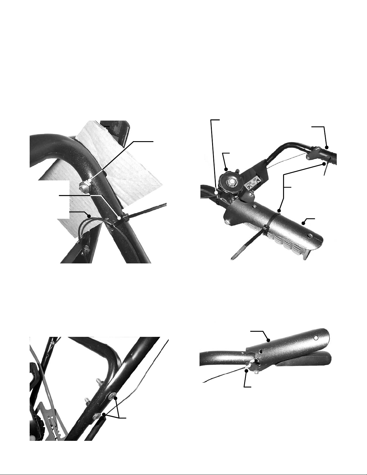
STEP 1: HANDLES: Cut both wire ties that secur e the
control cables to the handles. Be very careful and DO
NOT cut the control cables. See Figure 1.
REMOVE
CARDBOARD
ON BOTH
HANDLES
DO NOT CUT
CONTROL CABLE
FIGURE 1
STEP 2: HANDLES: Loosen handle nuts and rotate
handles up to the opera ting position. Remove ship ping
cardboard from in between handles. See Figure 1.
Insert bolts through both upper & lower handles and
secure with nuts. Make sure the square necks of the
bolts are recessed into the square holes of upper
handles. Tighten nuts securely. See Figure 2.
HANDLES WIT H
BOLTS AND NUTS
TIGHTEN SECURELY
FIGURE 2
STEP 3: HANDLES: Cut both wire ties that secure the
control levers to the handles. Cut the wire tie that
secures the chute crank to the handle. See Figure 3.
THAT SECURES
CHUTE CRANK
LEVER
CRANK
THAT SECURE THE
CONTROL LEVERS
TO THE HANDLES
LEVER
FIGURE 3
STEP 4: CABLES: Make sure that the “Z ” bend ends
of control cables are s ecured in t he holes on the c ontr ol
levers. Make sure cables are not kinked and have
freedom of movement when levers are engaged or
disengaged. See Figure 4.
LEVER
IS SECURELY INSERTED INTO
HOLE ON CONTROL LEVER
FIGURE 4
INSTRUCTIONS No. 7-4331 (Rev. 1, 4/08/02)
Page 2
2
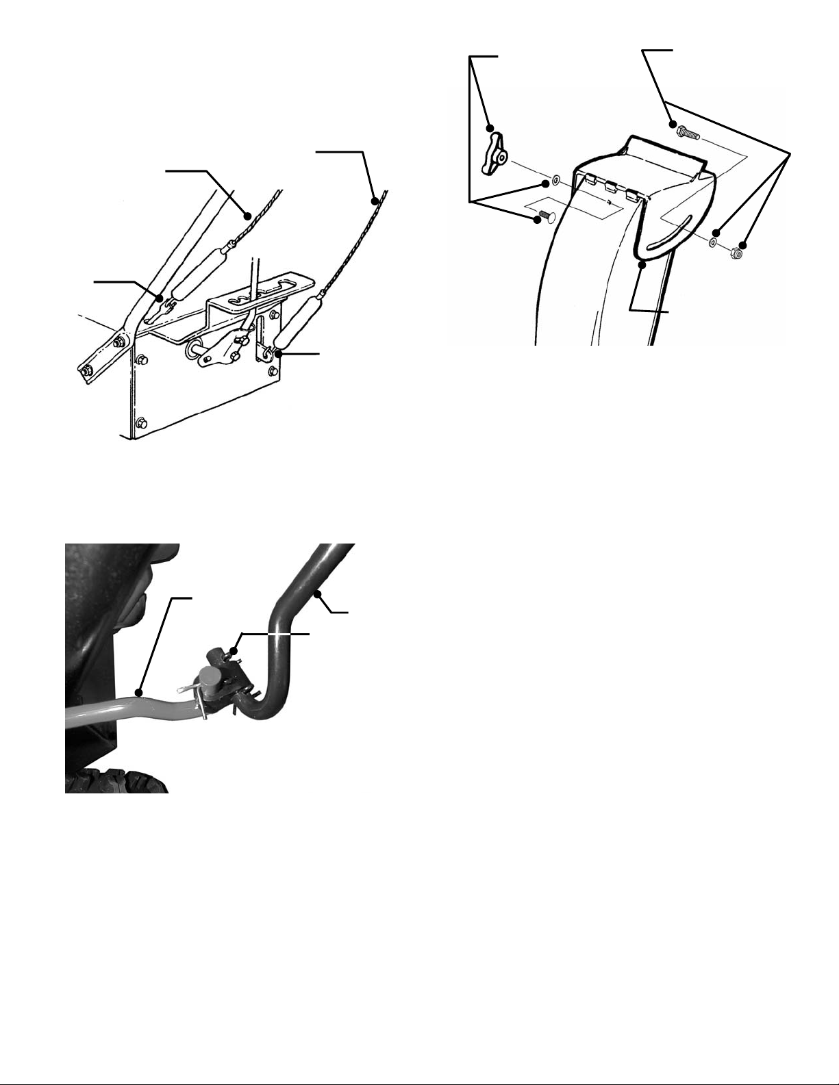
STEP 5: CABLES: Make sure that the cables are
BLOWER
TRACTION
TRACTION
BLOWER
CHUTE
SECURE WITH
WORM
INSTALL WING
DEFLECTOR MUST
INSTALL CAP
connected to the traction clutch rod and blower clutch
bracket. IMPORTANT: Cables should ha ve some slack
and should not be under tension. See Figure 5.
CLUTCH
CABLE
(LEFT SIDE)
CLUTCH
CABLE
(RIGHT SIDE)
CLUTCH
ROD
CLUTCH
BRACKET
FIGURE 5
STEP 6: CHUTE CRANK: Connect chute crank to worm
gear shaft and secure with cotter pin. See Figure 6.
GEAR
SHAFT
CRANK
COTTER PIN
FIGURE 6
STEP 7: DISCHARGE CHUTE DEFLECT OR: Secure
the deflector to the discharge chute using hardware
supplied in hardware bag. Tighten the cap screw,
washer and nut but allow deflector to rotate freely.
Install the carriage bolt, washer and wing nut. Tighten
securely. Use wing nut to securely lock deflector into
desired position. See Figur e 7.
NUT, WASHER
AND WING NUT
SCREW, WASH ER
AND NUT BUT DO
NOT OVER TIGHTEN
ROTATE FREELY
FIGURE 7
NOTE: After set-up the hardware bag will contain:
two shear bolts and two nuts and a cotter pin.
IMPORTANT: All necessary initial adjustments are
made to the machine at the factory. The following
cable adjustments and lu brication are provided for
reference only. Complete all items on the PreOperation Checklist as instructed.
Page 3

3
STEP 8: ADJUSTMENT: Adjust cable lengths s o that
SPRING SHOULD
TO ADJUST, LOOSEN JAM NUT
JAM
GEAR CASE
CHECK PLUG
each spring stretches 3/8” when the clutch lever is
depressed. When released, both clutch cables should
be slack. See Figure 8.
STRETCH 3/8”
WHEN HANDLE IS
DEPRESSED
CONNECTOR
NUT
AND TURN CONNECTOR TO
SHORTEN O R LENGTHEN
CABLE AS NEEDED TO ATTAIN
THE 3/8” EX TENSION. TIGHTEN
JAM NUT AFTER ADJUSTING.
FIGURE 8
STEP 9: LUBRICATION: Remove check plug to
check grease level i n auger gear case. If gr ease is not
visible from check plug hole, pump BENELENE 900
grease, SNAPPER Part No. 2-9577, into fill plug on
case until grease is visible. Reinstall check plug. See
Figure 9.
GREASE FITTING
FIGURE 9
STEP 10: CHECKLIST: Complete all item s on the Pre-
Operation Checklist as instructed.
Page 4

4
PRE-OPERATION CHECKLIST for
SNAPPER INTERMEDIATE FRAME SNOW THROWERS
Snapper has completed initial adjustments and performed operational tests prior to shipping the machine. Due
to the possible effects of shipping, handling and storage, Snapper intends for all of the following items to be
verified and necessary final adjustments made at time of setup. It remains good practice and is strongly
recommended that all t he items also be che cked prior to pla cing the machine in to service. It is v ery important
that setup is verified and all operational test s completed and results ar e ac cept able. After completin g t his f orm,
sign and retain for future reference.
LUBRICATION
_____ ENGINE OIL added to bring level up to full mark on 4-cycle engines (Refer to Engine Manual).
_____ GEAR CASE grease level check ed, add Benale ne 90 0 grease ( Sn app er Part No. 2-957 7) if needed .
OPERATIONAL TEST
_____ AUGER DRIVE CONTROL check ed for proper engag em ent and disengagem ent to insure auger s tops within 5
seconds after auger clutch control is released.
_____ WHEEL DRIVE CONTROL checked for proper engagement and disengagement of wheel drive.
_____ ENGINE started, engine speed control settings checked and adjusted as needed.
_____ IGNITION SWITCH checked to insure engine stops when turned to OFF position.
_____ ENGINE ELECTRIC STARTER checked for proper operation.
_____ FUEL SYSTEM checked for leaks around tank and connections.
______DISCHARGE CHUTE CRANK checked for proper operation and free rotation.
______AUGER and WHEEL DRIVE CONTROL CABLES checked and adjusted per instructions in the Operator’s Manual.
_____ GROUND SPEED CONTROL checked and adjusted per instructions in the Operator’s Manual.
_____ CHOKE CONTROL checked for proper operation during start up.
_____ TIRE PRESSURE checked. 15 to 20 PSI if chains are to be installed or 12 PSI if chains are not being used.
CONSUMER INFORMATION
Purchase Date __________________ Model_______________________ Serial No. _______________________
Retailers Name ___________________________________ ______________________________________________
Address _____________________________________ City ____________________ State _______ Zip ______
MACHINE WILL BE USED COMMERCIALLY? _____ YES _____ NO
Purchaser’s Name ________________________________ Signature ____________________________________
Address ____________________________________ City _____________________ State _______ Zip _______
IMPORTANT: Th is fo rm is to be ret ained fo r fu tu re r eferen c e reg ard ing W ar ra nt y, proof o f p urch as e, tr aceab i lity
for product recall or service, etc. Complete the Snapper Product Registration Card and Mail to Customer
Service Department at SNAPPER, P.O. Box 1379, McDonough, Georgia, 30253.
INSTRUCTION No. 7-4331 (Rev. 1, 4/08/02) Printed in U.S.A.
 Loading...