

Safety Instructions & Operator's Manual for

GARDEN TRACTORS & MOWER ATTACHMENTS
Thank you for buying a SNAPPER product! Your SNAPPER YARD TRACTOR was designed and built to provide long and satisfactory service. Keep in mind that it, like any other mechanical device, can be potentially dangerous if used improperly and that no accident prevention program can be successful without the wholehearted co-operation of the person responsible for the operation of the equipment. Study this manual and pay particular attention to the Important Safety Precautions on Page 2. Following these instructions will help you continue to enjoy the trouble-free performance expected of a SNAPPER product.

Printed in U.S.A.
MANUAL No. 2-4534 (REV. 2, 12/95)
IMPORTANT SAFETY INSTRUCTIONS
WARNING: This powerful cutting machine is capable of amputating hands and feet and can throw objects that can cause injury and damage! Failure to observe the following SAFETY Instructions could result in serious injury. Carefully read this manual and question your dealer if something is not clear. Should the dealer be unable to answer to your satisfaction, write or call the Customer Service Department at SNAPPER, McDonough, Georgia 30253 (Phone: (404) 954-2500).
PROTECTION FOR CHILDREN
- 1. DO NOT allow children in vard when machine is operated.
- 2. DO NOT allow children to ride on machine or on attachments.
- 3. DO NOT allow pre-teenage children to operate machine.
- 4. Only responsible teenagers with mature judgement shall be allowed to operate machine and only under close supervision.
PROTECTION AGAINST TIPOVERS
- 1. DO NOT operate machine on slopes exceeding 15 degrees (27% grade).
- 2. On slopes above 10 degrees (18% grade), exercise extreme CAUTION. Turn blade OFF when traveling uphill, also reduce speed and avoid sharp turns.
- 3. Avoid uphill starts. If machine is stopped going uphill, turn blade OFF and back slowly down the slope.
- 4. DO NOT mow under any condition where traction or stability is doubtful without first test driving over the terrain with blade OFF.
- 5. Stay alert for holes and other hidden hazards. Keep away from ditches, washouts, culverts, fences and protruding objects.
- 6. DO NOT now back and forth across face of slopes.
- 7. KEEP A SAFE DISTANCE (at least three feet) away from edge of ditches and other drop offs.
OTHER IMPORTANT PRECAUTIONS
- 1. Read and follow operator's manuals and instructions furnished with attachments.
- 2. Only mature, responsible persons shall operate the machine.
- 3. Mount and dismount machine from left side.
- 4. Wear appropriate protective clothing when mowing, such as, long pants and substantial footwear, not barefoot or with open sandals.
- 5. Practice operation of machine with blade OFF to learn controls and develop skill.
- 6. Persons under the influence of alcohol or drugs must NOT operate machine.
- 7. Know how to STOP blade and engine quickly in preparation for emergencies.
- 8. Keep people and pets a safe distance from machine.
- Shields, deflectors, switches, blade controls and other safety devices must be in proper position and functional.
- 10. Clear area to be worked of wire, rocks and other objects that could cause injury if thrown by blade.
- 11. STOP blade, STOP engine and remove key when leaving machine.
- 12. DO NOT operate machine unless properly seated with feet on foot rests or pedal.
- 13. Keep hands and feet away from rotating blade underneath deck. Never place foot on ground while blade is ON or when machine is in motion.
- 14. Turn blade OFF, STOP engine and wait for blade to STOP before attempting to unclog grass or leaves to prevent loss of fingers or hand.
- 15. Blade must be switched OFF except when cutting grass. Set cutter in highest position when mowing over rough ground.
- 16. Deflector or grass catcher must be in position. Never point discharge at people, passing cars, windows or doors. Watch out for traffic when crossing or near roadways.
- 17. Operate in reverse only after careful observation of entire area behind the machine. DO NOT mow in reverse unless absolutely necessary.
- 18. Service machine and make adjustments only when engine is stopped.
- 19. Have machine serviced by an authorized SNAPPER dealer at least once a year and have the dealer install any new SAFETY devices.
- 20. Use only genuine SNAPPER replacement parts to assure that original standards are maintained.
- 21. Tighten all nuts, bolts and screws frequently, then check, adjust, repair or replace brakes as needed.
- 22. Lubricate machine at intervals specified in manual to prevent controls from binding.
- 23. Mow only in daylight or with good artificial light.
- 24. Handle gasoline with care! Never remove cap while engine is running. Fill tank outdoors only with engine STOPPED and cool. Clean spilled gasoline from machine. Store gasoline in approved container, out of the reach of children, in well ventilated, unoccupied building.
- 25. DO NOT change engine governor speed settings or overspeed engine.
- 26. Check grass catcher components frequently for signs of wear or deterioration and replace as needed to prevent injury from items going through weak or worn spots.
- 27. Exercise CAUTION when pulling loads. Limit loads to those you can safely control and attach loads to hitch plate as specified with SNAPPER attachment instructions.
OPERATING INSTRUCTIONS
INTRODUCTION: Become thoroughly familiar with the location of all controls and the function of each BEFORE operating the machine. Make sure each operator reads the important SAFETY PRECAUTIONS on page 2 of this manual and all SAFETY related messages on the tractor and attachments.
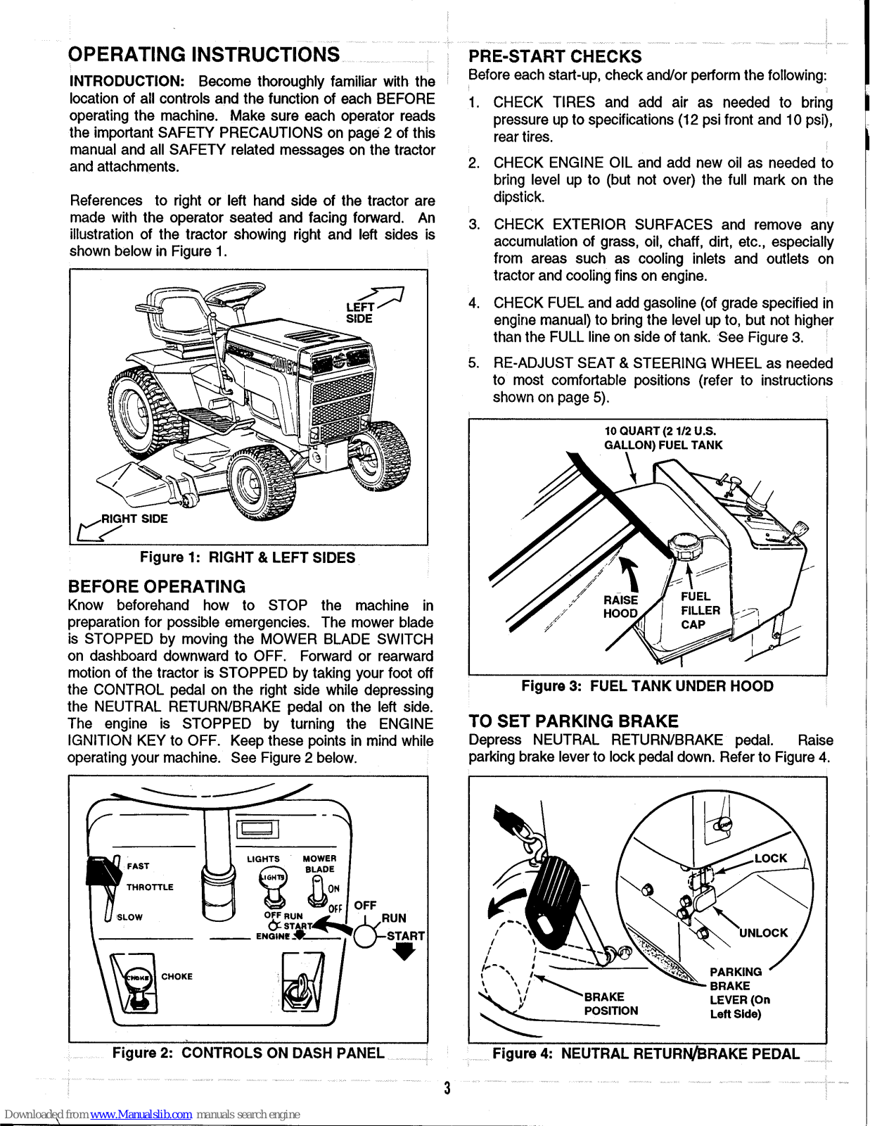
References to right or left hand side of the tractor are made with the operator seated and facing forward. An illustration of the tractor showing right and left sides is shown below in Figure 1.

Figure 1: RIGHT & LEFT SIDES
BEFORE OPERATING
Know beforehand how to STOP the machine in preparation for possible emergencies. The mower blade is STOPPED by moving the MOWER BLADE SWITCH on dashboard downward to OFF. Forward or rearward motion of the tractor is STOPPED by taking your foot off the CONTROL pedal on the right side while depressing the NEUTRAL RETURN/BRAKE pedal on the left side. The engine is STOPPED by turning the ENGINE IGNITION KEY to OFF. Keep these points in mind while operating your machine. See Figure 2 below.

PRE-START CHECKS
Before each start-up, check and/or perform the following:
- 1. CHECK TIRES and add air as needed to bring pressure up to specifications (12 psi front and 10 psi), rear tires.
- 2. CHECK ENGINE OIL and add new oil as needed to bring level up to (but not over) the full mark on the dipstick.
- 3. CHECK EXTERIOR SURFACES and remove any accumulation of grass, oil, chaff, dirt, etc., especially from areas such as cooling inlets and outlets on tractor and cooling fins on engine.
- 4. CHECK FUEL and add gasoline (of grade specified in engine manual) to bring the level up to, but not higher than the FULL line on side of tank. See Figure 3.
- 5. RE-ADJUST SEAT & STEERING WHEEL as needed to most comfortable positions (refer to instructions shown on page 5).

Figure 3: FUEL TANK UNDER HOOD
TO SET PARKING BRAKE
Depress NEUTRAL RETURN/BRAKE pedal. Raise parking brake lever to lock pedal down. Refer to Figure 4.

STARTING ENGINE:
1. The GT180H TRACTOR is equipped with interlocks to prevent STARTING of the engine until the following conditions are met:
A. The NEUTRAL RETURN/BRAKE pedal must be fully depressed.
B. The MOWER BLADE switch must be in the OFF position.
The seat interlock is a function to shut OFF the engine in the event the operator's seat is vacated while the machine is in operation. In the event of an interlock malfunction, DO NOT continue operating the tractor until the condition is corrected.
- 2. Pull the CHOKE knob all the way out to START cold engine. Little or no choking will be needed when RE-STARTING a warm engine.
- 3. Move engine THROTTLE past midpoint into a FAST setting. You may have to vary the setting somewhat at first to find the best position for your engine.
- 4. Insert key into ENGINE IGNITION SWITCH, turn key to START position to crank engine and hold until engine STARTS, then release. NOTE: Limit cranking intervals to five seconds duration to prevent overheating of starting motor and/or depletion of battery energy. Normally, five seconds is sufficient cranking time for STARTING. If this time is exceeded, locate and correct cause of STARTING problem.
- 5. As engine warms, gradually depress CHOKE knob into the control panel. Move THROTTLE to desired engine speed setting.
TO START MOTION
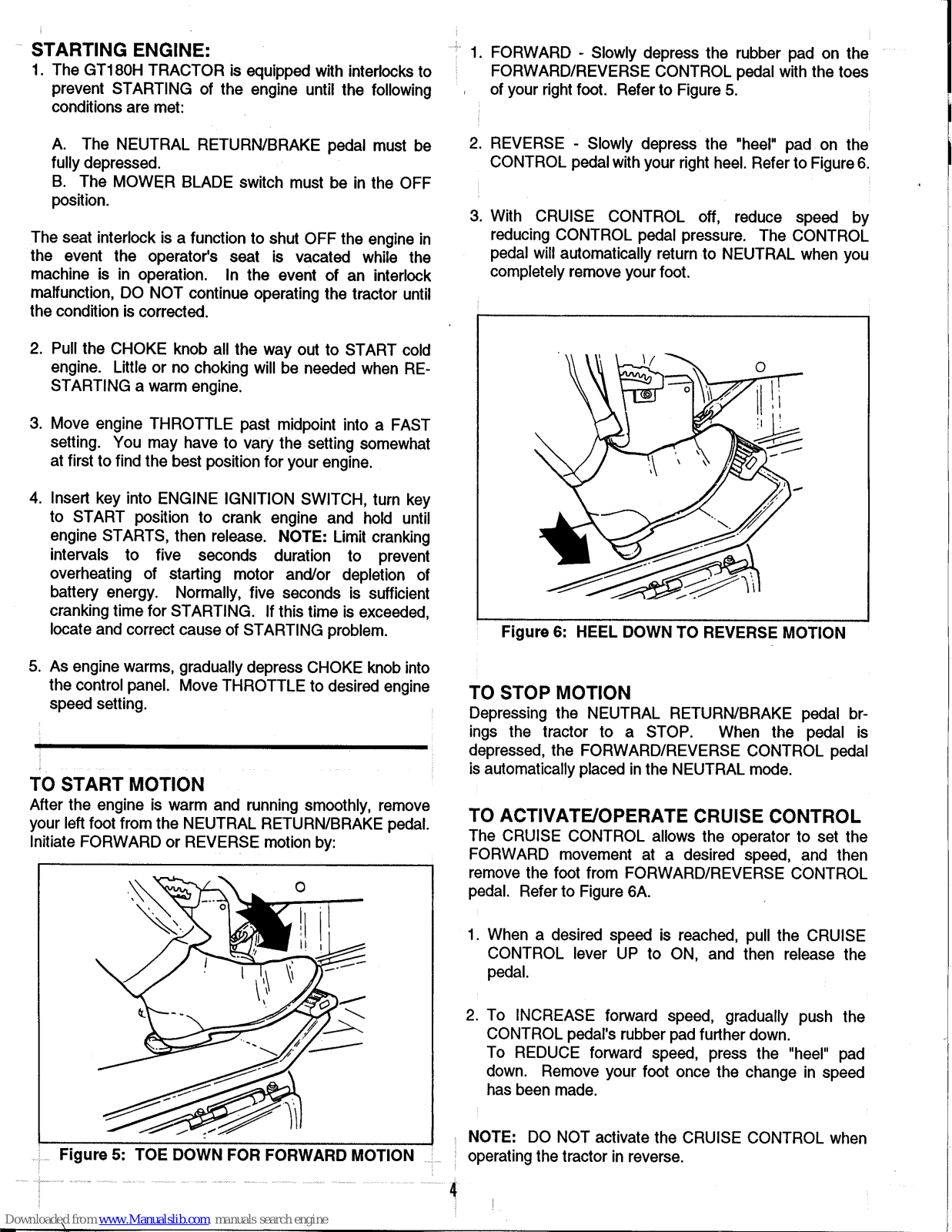
After the engine is warm and running smoothly, remove your left foot from the NEUTRAL RETURN/BRAKE pedal. Initiate FORWARD or REVERSE motion by:

- 1. FORWARD Slowly depress the rubber pad on the FORWARD/REVERSE CONTROL pedal with the toes of your right foot. Refer to Figure 5.
- 2. REVERSE Slowly depress the "heel" pad on the CONTROL pedal with your right heel. Refer to Figure 6.
- 3. With CRUISE CONTROL off, reduce speed by reducing CONTROL pedal pressure. The CONTROL pedal will automatically return to NEUTRAL when you completely remove your foot.

Figure 6: HEEL DOWN TO REVERSE MOTION
TO STOP MOTION
Depressing the NEUTRAL RETURN/BRAKE pedal brings the tractor to a STOP. When the pedal is depressed, the FORWARD/REVERSE CONTROL pedal is automatically placed in the NEUTRAL mode.
TO ACTIVATE/OPERATE CRUISE CONTROL
The CRUISE CONTROL allows the operator to set the FORWARD movement at a desired speed, and then remove the foot from FORWARD/REVERSE CONTROL pedal. Refer to Figure 6A.
- 1. When a desired speed is reached, pull the CRUISE CONTROL lever UP to ON, and then release the pedal.
- To INCREASE forward speed, gradually push the CONTROL pedal's rubber pad further down. To REDUCE forward speed, press the "heel" pad down. Remove your foot once the change in speed has been made.
NOTE: DO NOT activate the CRUISE CONTROL when operating the tractor in reverse.
TO DEACTIVATE CRUISE CONTROL
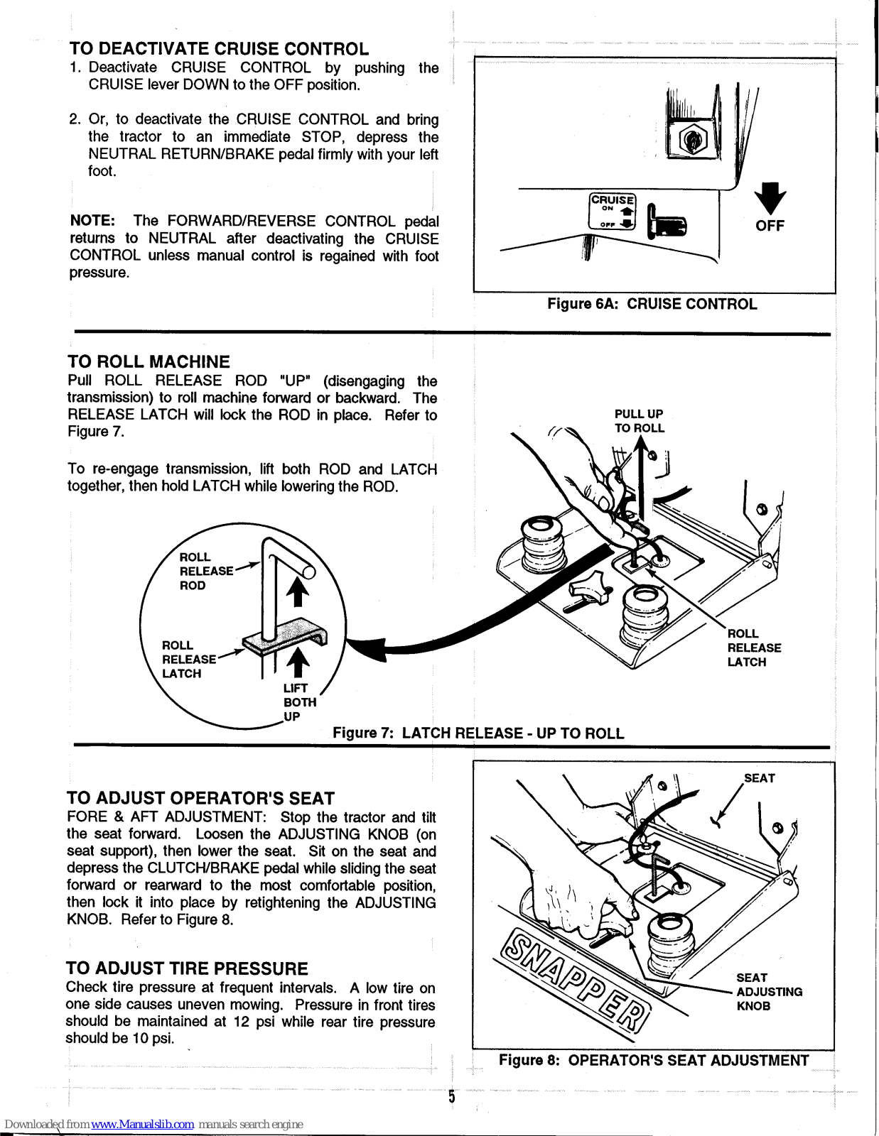
- 1. Deactivate CRUISE CONTROL by pushing the CRUISE lever DOWN to the OFF position.
- 2. Or, to deactivate the CRUISE CONTROL and bring the tractor to an immediate STOP, depress the NEUTRAL RETURN/BRAKE pedal firmly with your left foot.
NOTE: The FORWARD/REVERSE CONTROL pedal returns to NEUTRAL after deactivating the CRUISE CONTROL unless manual control is regained with foot pressure.

Figure 6A: CRUISE CONTROL
TO ROLL MACHINE
Pull ROLL RELEASE ROD "UP" (disengaging the transmission) to roll machine forward or backward. The RELEASE LATCH will lock the ROD in place. Refer to Figure 7.
To re-engage transmission, lift both ROD and LATCH together, then hold LATCH while lowering the ROD.

Figure 7: LATCH RELEASE - UP TO ROLL
TO ADJUST OPERATOR'S SEAT
FORE & AFT ADJUSTMENT: Stop the tractor and tilt the seat forward. Loosen the ADJUSTING KNOB (on seat support), then lower the seat. Sit on the seat and depress the CLUTCH/BRAKE pedal while sliding the seat forward or rearward to the most comfortable position, then lock it into place by retightening the ADJUSTING KNOB. Refer to Figure 8.
TO ADJUST TIRE PRESSURE
Check tire pressure at frequent intervals. A low tire on one side causes uneven mowing. Pressure in front tires should be maintained at 12 psi while rear tire pressure should be 10 psi.

RELEASE
LATON
TO ADJUST STEERING WHEEL
After the operator's seat has been adjusted to the most comfortable position, sit in the operator's seat and set the steering wheel to the most comfortable position. To adjust, grasp the steering column and push down, then turn the wheel to the left to tilt forward or to the right to tilt down. Make sure the steering wheel does not interfere when getting on and off the tractor.
TO OPERATE MOWER
During transport or for clearance through gates, it may become necessary to raise the discharge deflector. Reinstall the wing nuts on the studs when the deflector is raised so they will not be lost. Be sure to lower the deflector and clamp it securely down with the wing nuts BEFORE mowing.
The cutting height can be changed to any one of nine positions by raising or lowering the cutting deck attachment with the implement lift lever as shown in Figure 10.
To prevent accidental starting of the blades, the MOWER BLADE SWITCH (as shown in Figure 2) is designed so that it must be pulled out before it can be moved forward to the blade ON position.
Because of different conditions, experiment by increasing engine speed and/or decreasing driving speed until smoothest cut is obtained. Best performance is achieved at full throttle.
SERVICE
To retain the quality of your tractor, use Genuine SNAPPER Replacement Parts only! Contact your local SNAPPER Dealer for parts and service assistance. For the correct part or information for your particular mower, always mention model and serial number. We recommend returning the tractor to an authorized SNAPPER Dealer on a yearly basis for inspection and addition of any new devices which might upgrade the SAFETY of your mower. For the nearest SNAPPER Dealer, check the Yellow Pages under the heading, LAWN MOWERS. For engine parts and service, look for the engine manufacturer's dealers under the heading, ENGINES - Gasoline.
SERVICE ACCESS: To raise hood full forward for service access to the engine, pull the hairpin from the post as shown in Figure 11 and disconnect the cable from the retaining post.

Figure 9: STEERING WHEEL ADJUSTMENTS

Figure 10: IMPLEMENT LIFT LEVER

Figure 11: SERVICE ACCESS TO ENGINE

Figure 12: ENGINE OIL CHECK
MAINTENANCE & LUBRICATION SCHEDULE
Refer to the engine owner's manual for service specifications on the engine itself. The following applies primarily to the tractor and optional mower attachments. Clean fittings before greasing.
FIRST 5 HOURS (New Unit)
ENGINE OIL: Change oil in crankcase. Refer to engine owner's manual. Refer to Figure 12.
HYDRAULIC RESERVOIR: Check level in hydraulic reservoir. Add oil as required.
TRACTOR: Check all fasteners and retighten as needed.
EVERY 25 OPERATING HOURS
- FRONT WHEEL BEARINGS: Lubricate bearings through the lube fitting on hub of front wheel. See Figure 13.
- FRONT AXLE PIVOT & SPINDLES: Lubricate spindle lube fittings on each end of axle and the center pivot lube fitting on underside of the front axle. See Figure 14.
- CHANGING OIL IN ENGINE CRANKCASE: Select oil of weight and grade specified in engine owner's manual. See Figure 15.
- ENGINE AIR CLEANER: Refer to engine owner's manual for details.
IDLER (42" MOWER): Lubricate bearing thru lube fitting on idler arm pivot.
TWICE YEARLY SERVICE
(Or Every 50 Hours)
LUBRICATE FITTINGS with two shots of grease on:
- 1. Steering mechanism located beside gas tank.
- Steering sector gear pivot under gas tank. See Figure 14.
END OF EACH SEASON
(Or Every 100 Hours)
MOWER ATTACHMENT SPINDLE(S): Lubricate fitting for blade spindle bearings with two shots only of bearing grease once each year.
SERVICE Engine air cleaner element and also check spark plug.
SERVICE FUEL FILTER: See instruction and Figure 19 on page 9.
DRAINING ENGINE OIL
The oil drain plug is located on the bottom of the engine in the approximate center of the oil pan just to the rear of the front tie rod. A 1/4" allen head wrench is required to remove the plug. Refer to the engine owner's manual for engine oil specifications.

STEEDING LIET SHAFT. PIVOT HOUSING STEERIN SECTOR -GEAR PIVOT EDON LUBE DIVOT EITTING WUCCI LUBE BEARINGS EITTING
Figure 14: LUBRICATION POINT SCHEMATIC

Figure 15: ENGINE OIL DRAIN LOCATION

Figure 16: CENTER COVER REMOVAL
ACCESS TO BATTERY & HYDRAULIC RESERVOIR
The battery and hydraulic fluid reservoir are located under the center cover. To remove the cover, turn the two retaining knobs as shown in Figure 16 to the left until removed, then slide the cover to the rear and lift out. DO NOT operate the tractor with this cover removed.
HYDRAULIC FLUID CHECK
Twice yearly, remove the center panel as described above to check the level of the fluid in the hydraulic fluid reservoir. Wipe away all dirt and debris from around reservoir cap before removing. Oil must remain absolutely clean! Check with tractor on level surface with engine OFF. Fill reservoir as needed to bring level up to 1 1/2 to 2 inches below the top of the filler neck. Use clean, fresh 20W non-detergent motor oil. Make sure funnels, pouring spouts and oil can are completely clean. Reinstall filler cap.
BATTERY SERVICE
Check the battery once each month. Remove the caps and add distilled water as necessary to bring the level of the electrolyte up to about 3/32" over plates in each cell. DO NOT FILL TO THE RINGS. Carefully reinstall battery caps. In freezing weather, charge the battery after adding water to thoroughly mix the water in the electrolyte. Keep the terminals and straps clean and tight and make sure the RED BOOT remains in position over the positive terminal. Refer to Figure 17. Always disconnect the negative (-) terminal first and reconnect last!
The engine is equipped with a flywheel alternator to charge the battery. If the tractor is not run regularly, connect the battery to a charger at frequent intervals to maintain the specific gravity at 1.250 or higher. If this reading falls below 1.175, the battery liquid may freeze when temperatures drop to around zero degrees F. To charge, connect the battery as per instructions furnished with the charger. If time allows, slow charge at 1 amp for

Figure 17: BATTERY & HYDRAULIC RESERVOIR
ten hours, or as an alternate, fast charge at 3 amps for four hours. Observe ALL PRECAUTIONS while charging. NOTE: To maintain battery charge, run the engine frequently at medium to high speed for 1/2 to 1 hour intervals.

Figure 18: ELECTRIC CLUTCH ADJUSTMENT
ELECTRIC CLUTCH ADJUSTMENT
Should the mower blade take more than five seconds to STOP after the mower blade is switched OFF, the brake plate may need adjusting. When properly adjusted, a .010" feeler gauge will fit thru the opening on both sides and bottom of the clutch as shown in Figure 18. To adjust, turn the 3 adjusting nuts in or out as needed to obtain the .010" clearance.
FUEL SYSTEM SERVICE
The in-line fuel filter (between fuel tank and engine) protects the engine from damage due to gasoline impurities. Also, check the hose clamps for any leakage. Replace the filter, SNAPPER P.N. 1-4359 before the screen becomes completely clogged with sediment. When the fuel filter appears dark in the screen area, and/or if the engine becomes "starved" for fuel, it will not accelerate properly and will miss or stall under load. The fuel filter should then be replaced. Refer to Figure 19.


Figure 20: SCHEMATIC WIRING DIAGRAM

Downloaded from www Manualslib com manuals search engine
CUTTING BLADE SERVICE
Check at frequent intervals to make sure the blade is securely tightened and that it is in good condition.
Replace blade if badly chipped, bent, out of balance, or as soon as notch starts wearing in the tip between the flat surface and upturned lift as depicted in View B,Figure 21. This type of wear pattern occurs more rapidly under sandy soil conditions. CAUTION: NEVER operate the mower with blade worn to the extent shown in View C, as the TIP could fly OFF causing personal injury or property damage.
Sharpen blade(s) when the cutting edges become dull. When the blade gets dull, the grass cut ends will be ragged and will usually turn brown soon after mowing. For best results, remove the blade and sharpen it on a grinding wheel at an angle of 22 to 28 degrees. The cutting surface should extend in about 2 1/2" from the tips. Check the blade after sharpening to determine that it is still balanced. It will cause excessive vibration if unbalanced.
BE CAREFUL - AVOID CUTTING YOURSELF ON SHARP BLADE!

Figure 23: BLADE SHARPENING DETAIL
Install sharpened or replacement blade with components in same sequence as removed. Make sure that the turned-up rims in the center of the blade fit over the edges of the blade drive hub when installing. DO NOT substitute any components here! Tighten the blade retaining capscrew to 20-30 foot-pounds torque on 42" and 48" mowers and to 50-70 foot-pounds torque on 33" mowers.
MOWER DRIVE BELT SERVICE
The drive arrangement for each of the three available mowers is show in Figure 24. To install or replace the belt, loosen the pulleys of the "mule" drive at front, loop the belt around the electric clutch pulley and route it inside the "mule" drive pulley as shown and around the pulleys of the mower. NOTE: To get the belt around the pulleys on the multi-blade mowers, the belt covers on the outside pulleys must be removed. DO NOT operate the mower WITHOUT these covers - ALWAYS reinstall covers!
MOWER ATTACHMENTS
The following applies to the single blade 33" mower, the multi-blade 42" and 48" mowers furnished with the GTH Series Garden Tractors. Other attachments such as the Snow Thrower are covered in instructions furnished with the particular attachments
If the mower is to be removed for any reason such as cutting blade service, or to install another attachment, be sure the mower settings remain unchanged. Simply pull clevis pins attaching he mower to the front and rear lift arms and lift bracket after removing the drive belt. Turn the front wheels to the left
and slide the mower out from the right side. Use the following procedure to install the mower to the tractor.
MOWER SERVICE & ADJUSTMENTS: Keep the topside of the mower free of grass cuttings. Build-up of clippings could cause belt problems and also might present potential fire hazard especially when dry. If uneven cutting is noted, check the tire pressure first as this is the most common cause. If tire pressure is correct and uneven cutting persists, move the tractor to a flat level surface, such as a garage floor, and check the deck level.

FIG. 24 - MOWER BELT ROUTING DETAIL
REMOVING & INSTALLING MOWER
The mower is attached to the tractor and levelled at the factory. If the mower is to be removed for cutting blade service, or to install another attachment, be sure that the mower settings remain unchanged. Simply pull clevis pins attaching the mower to the front and rear lift arms and lift bracket after removing the drive belt. Turn the front wheels to the left and slide the mower out from the right side. Use the following procedure to install the mower to the tractor.
1. Turn front wheels to left, slide mower in from right side until in position under tractor.
2. Unplug lights, remove hairpins in hood stop cables, remove hood, attach mule drive*to front of tractor with two bolts.* if removed
3. Grasp deck belt above mule drive pulleys, pull upward and loop over and wrap around the engine pulley. Check belt routing. Reinstall hood on tractor, hook up lights and stop cables.

FIG. 25 - REAR LIFT ARM DETAIL
4. Pull front lift arms up into position between the implement attaching brackets on back of front axle and secure at each side with a large clevis pin and large hairpin. Refer to FIG. 26.
5. Place implement lift lever in lowest position (full forward), raise deck and secure to rear lift arm bracket with washer and small hairpin. (FIG. 10)
6. Slip ball end of cable attached to front lift arm into slot in the clevis then attach the clevis to the lift lever bracket with small clevis pin and small hairpin. Refer to FIG. 27.

FIG. 26 - FRONT LIFT BRACKET

FIG. 27 · FRONT LIFT ARM DETAIL

FIG. 28 · MULTI-BLADE LEVEL CHECK
LEVELING - 33" MOWER
With the blades sharpened and properly aligned, a level mower deck will insure a clean, even cut. The mower should be checked for level as follows:
1. Check the air pressure in the tires and correct pressure as needed. 12 psi front and 10 psi rear tires.
2. Move the tractor to a smooth, flat and level area such as garage floor.
3. Move the lift lever to #5 notch.
4. Place a 2 3/4" block on edge under the front lip of the deck in the exact center between the front lift arms.
5. Loosen the jam nut on the front lift cable and adjust until the front lip of the deck rests on the block and the cable is tight. Tighten the cable jam nut and remove the block.
6. Place a 2 3/4" high block under the exact center of the rear lip of the deck.
7. Pull the pins and remove the chains from the support pins on the rear lift arms.
8. Loosen nuts on eccentric bolt and pivot bolt and level the deck side to side by turning the eccentric adjusting bolt. The distance from the floor to the bottom of the deck on the left & right side should be within 1/8" of each other.
YE BOLT
AM NH


NOTE: MOWER SHOWN WITH BELT GUARDS RE-MOVED FOR ILLUSTRATION PURPOSES ONLY!
FIGURE 29: 33" MOWER LEVELING DETAIL
REAR LIFT ARM DETAIL
With the blades sharpened and properly aligned, a level mower deck will insure a clean, even cut. The mower should be checked for level as follows:
1 Check the air pressure in the tires and correct pressure as needed. 12 psi front and 10 psi rear tires.
2 Move the tractor to a smooth flat and level area such as garage floor
3 Move the lift lover to #5 noteb
4. Place a 2x4" block on edge under the front lip of the deck in the exact center between the front lift
5. Loosen the jam nut on the front lift cable and adjust until the front lip of the deck rests on the 2x4 block and the cable is tight. Tighten the cable iam nut and remove the block
6. Place a 3" high block under the exact center of the rear lip of the deck.
port pins on the rear lift arms
8 Turn the outside blades perpendicular to the tractor frame
9. Loosen nuts on eccentric bolt and pivot bolt and level the deck side to side by turning the eccentric tip should be within 1/8" of each other.
10. Loosen the iam nuts and adjust both rear lift chain evebolts so that the top link of the chain just slides over the rear arm pins. Tighten jam nuts. Reinstall the flat washers and hairning Recheck level.


FIGURE 30: 42" MOWER LEVELING DETAIL
With the blades sharpened and properly aligned, a level mower deck will insure a clean, even cut. The mower should be checked for level as follows:
1. Check the air pressure in the tires and correct pressure as needed, 12 psi front and 10 psi rear tires.
2. Move the tractor to a smooth, flat and level area such as garage floor.
3. Move the lift lever to #5 notch.
4. Place a 2x4" block on edge under the front lip of the deck in the exact center between the front lift arms.
5. Loosen the jam nut on the front lift cable and adjust until the front lip of the deck rests on the 2x4 block and the cable is tight. Tighten the cable jam nut and remove the block.
6. Place a 3" high block under the exact center of the rear lip of the deck.
7. Pull the pins and remove the chains from the support pins on the rear lift arms.
8. Turn the outside blades perpendicular to the tractor frame.
9. Loosen nuts on eccentric bolt and pivot bolt and level the deck side to side by turning the eccentric adjusting bolt. The distance from floor to each blade tip should be within 1/8" of each other.
REAR LIFT ARM DETAIL

slides over the rear arm pins. Tighten jam nuts.
Reinstall the flat washers and hairpins. Recheck
FRONT LIFT CABLE
FIGURE 31: 48" MOWER LEVELING DETAIL
level.

GT180H SERIES 4 & 5 GENERAL SPECIFICATIONS
| and the second | |||
|---|---|---|---|
| MODEL | GT180H33 | GT180H42 | GT180H48 |
| FUEL TANK CAPACITY | 2.5 U.S. GAL. | 2.5 U.S. GAL. | 2.5 U.S. GAL. |
|
FRONT TIRE SIZE
FRONT TIRE PRESSURE |
15x6.00-6
12 psi |
15x6.00-6
12 psi |
15x6.00-6
12 psi |
|
REAR TIRE SIZE
REAR TIRE PRESSURE |
21x7.00-10
10 psi |
23x10.5-12
10 psi |
23x10.5-12
10 psi |
|
LENGTH (OVERALL)
WIDTH (OVERALL) HEIGHT OVERALL) |
67.25″
33.75″ 42.0″ |
68.25
"
38.5 " 44.0 " |
68.25″
38.5″ 44.0″ |
| 553 LBS. | 588 LBS. | 623 LBS. | |
|
SPEED · FORWARD
SPEED · REVERSE |
6.12 MPH
3.3 MPH |
6.8 MPH
3.7 MPH |
6.8 MPH
3.7 MPH |
|
TRANSMISSION -
• HYDROSTATIC TRANSAXLE |
EATON
851 |
EATON
851 |
EATON
851 |
|
• ENGINE KOHLER 18 HP "MAGNUM" TWIN CYLINDER
WITH 15 AMP FULLY REGULATED CHARGING SYSTEM. |
|||
BATTERY -- 12 VOLT. 20 AMP HOUR
unanananananananananananananananananana
2 YEAR LIMITED WARRANTY
For two (2) years from purchase date for the original purchaser's residential, non-commercial use, SNAPPER, through any SNAPPER dealer will replace, free of charge, any part or parts found upon examination by the factory at McDonough, Georgia, to be defective in material or workmanship or both.
For ninety (90) days from purchase date for the original purchaser's commercial , rental, or other non-residential use, SNAPPER , through any SNAPPER dealer will replace, free of charge, any part or parts found upon examination by the factory at McDonough, Georgia, to be defective in material or workmanship or both.
All transportation costs incurred by the purchaser in submitting material to a SNAPPER dealer for replacement under this warranty must be paid by the purchaser.
This warranty does not apply to engines and their components, or, Peerlesse Transaxles, as these items are warranted separately by their manufacturers. This warranty does not apply to parts that have been damaged by accident, alteration, abuse, improper lubrication, normal wear, or other cause beyond our control.
There is no other express warranty.
Implied warranties, including those of merchantability and fitness for a particular purpose, are limited to two (2) years from purchase date for the original purchaser's residential, non-commercial use [ninety (90) days from purchase for the original purchaser's commercial, rental or other non-residential use], and to the extent permitted by law, any and all implied warranties are excluded. This is the exclusive remedy. Liabilities for consequential damages, under any and all warranties are excluded.
Some states do not allow limitations on how long an implied warranty lasts, or do not allow the exclusion or limitation of incidental or consequential damages, so the above limitation or exclusion may not apply to you.
This warranty gives you specific legal rights, and you may also have other rights which vary from state to state.
WARNING: THE USE OF REPLACEMENT PARTS OTHER THAN GENUINE SNAPPER PARTS MAY IMPAIR THE SAFETY OF SNAPPER PRODUCTS AND WILL VOID ANY LIABILITY AND WARRANTY BY SNAPPER ASSOCIATED WITH THE USE OF SUCH PARTS.
IMPORTANT: Please fill out the attached SNAPPER Product Registration Card immediately and mail to: SNAPPER, McDONOUGH, GEORGIA 30253
87 8

MANUAL No. 2-4534 (REV. 2, 12/95)


 Loading...