

Page 1
1
DEALER SETUP AND CHECKLIST FOR
LUG NUTS
SNAPPER GROUNDS CRUISER UTILITY VEHICLE
INTRODUCTION: These instructions cov er the setup of the Snapper Grounds Cruiser utility vehicle. Complete
each step carefull y. A checklist h as been provid ed. It is v ery important to v erify and record each item on t he
list prior to retail. The dry weight of the machine you are about to setup is 1,230 lb. It is strongly recommended
that you use an overhead hoist when lifting the machine. The capacity of the device used for lifting must
exceed the weight of th e machin e. DO NO T work on the machine un til p roperly blocked and s ecur ed to prevent
it from falling. If an overhead hoist is not available, you may have to remove boards from the crate bottom to
gain access with floor type jacks.
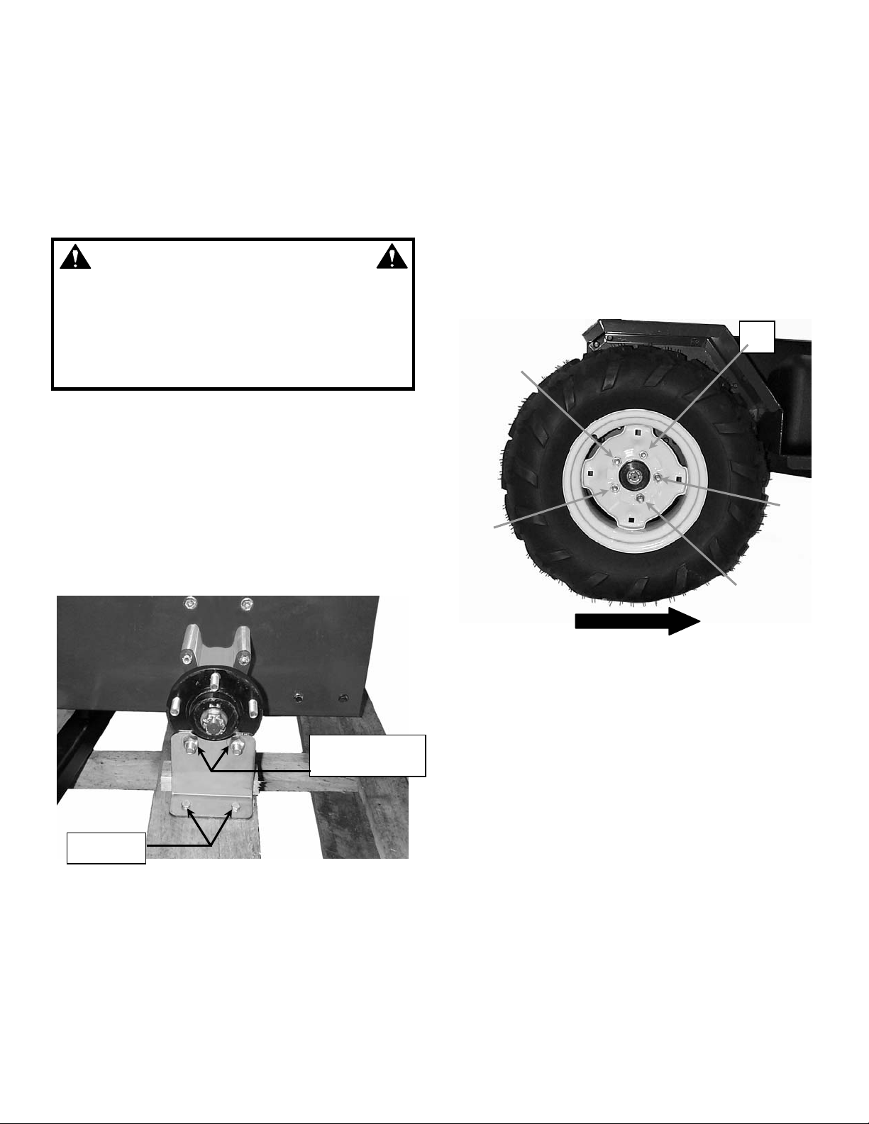
4. Install left and right rear tires and secure each with
WARNING
DO NOT attempt any adjustments, maintenance or
service with the engine running. STOP engine. Set
park brake. Shift transmission to neutral and
remove key. Remove spark plug wire from spark
plug and secure wi re away from sp ark plug. Eng ine
and components are HOT. Avoid serious burns,
allow all parts to cool before working on machine.
STEP 1
INSTALL REAR TIRES
The machine is secur ely attached to the c rate bottom at
each wheel location. See Figure 1.1. The four steel
plates must be rem oved before lifting t he machine. The
device used to lift the machine must have a capacity
greater than 1230 lb. The c argo bed is attached to the
frame of the machine with plastic straps. Carefully
remove the straps and set the cargo bed aside for
installation later.
5 lug nuts. NOTE: The tir es are directional. Instal l
with valve stem out and the points of the chevron
treads pointing forward. See Figure 1.2.
3
1
5
4
2
(LOOSEN ONLY)
REMOVE
FIGURE 1.1
1. Loosen only, two lug nuts at left and right rear
wheel hubs.
2. Remove the four bolts securing the left and right
support plates to the crate bottom.
3. Lift machine, at t he rear hitch, onl y high enough to
allow tire installation. Block machine securely to
prevent it from falling. Remove support plates.
POINTS OF TREADS POINTING TOWARD FRONT OF VEHICLE.
FIGURE 1.2
5. Remove blocks and lower rear of machine.
6. Torque lug nuts to 75 f t-lb using sequence shown.
See Figure 1.2.
STEP 2
INSTALL FRONT BUMPER
The bolts used to attach the front bumper to the
machine are already installed in the front frame. The
bumper can be used t o lift the weight of the f ront of the
machine. The mounting hardware must be tightened
securely (30 ft-lb).
1. Place bumper over f our bolts at front of fram e. Note
orientation, flat side of side plates towards bottom
2. Attach using (4) 3/8-16 flange lock nuts.
3. Torque nuts to 30 ft-lb.
INSTRUCTION No. 7-3574 (REV. 1, 8/25/00)
Page 2
2
STEP 3
REPRESENTING
SEAT
MOUNT
7/16-20X2”
1/2”X1
-
1/4”
1/2”X1
-
1/4”
7/16-20
2-1/2”
INSTALL FRONT TIRES
The front bumper can be used to lift the front of the
machine. Block the machine to prevent it from falling.
NOTE: The front tires are directional. Install with valve
stems out and with the points of the chevron treads
pointing forward.
1. Loosen only, two lug nuts at left and right front
wheel hubs.
2. Remove the four bolts securing the left and right
support plates to the crate bottom.
3. Lift front of machine on ly hi gh en oug h to ins t al l f r ont
tires. Block machine securely to prevent it from
falling. Remove support plates.
4. REMOVE OPERATOR PROTECTIVE STRUCTURE
FROM CRATE B OTTOM A T TH IS TI ME.
5. Install left and right f ront tires and s ecure each with
5 lug nuts.
6. Remove blocks and lower machine.
7. Torque lug nuts to 75 f t-lb using sequence shown.
See Figure 1.2.
STEP 4
ADJUST TIRE PRESSURE
IMPORTANT! C orr ect tir e i nflatio n pres sur e is cr itic al to
the proper handling and braking of the machine.
1. Using a low-pressure tire gauge, check tire
pressure.
2. Adjust tire pressure to 15 psi.
WARNING
Operator Protectiv e Structure and Seat Belts must
be installed and all mounting hardware tightened
securely before starting or operating machine.
STEP 5
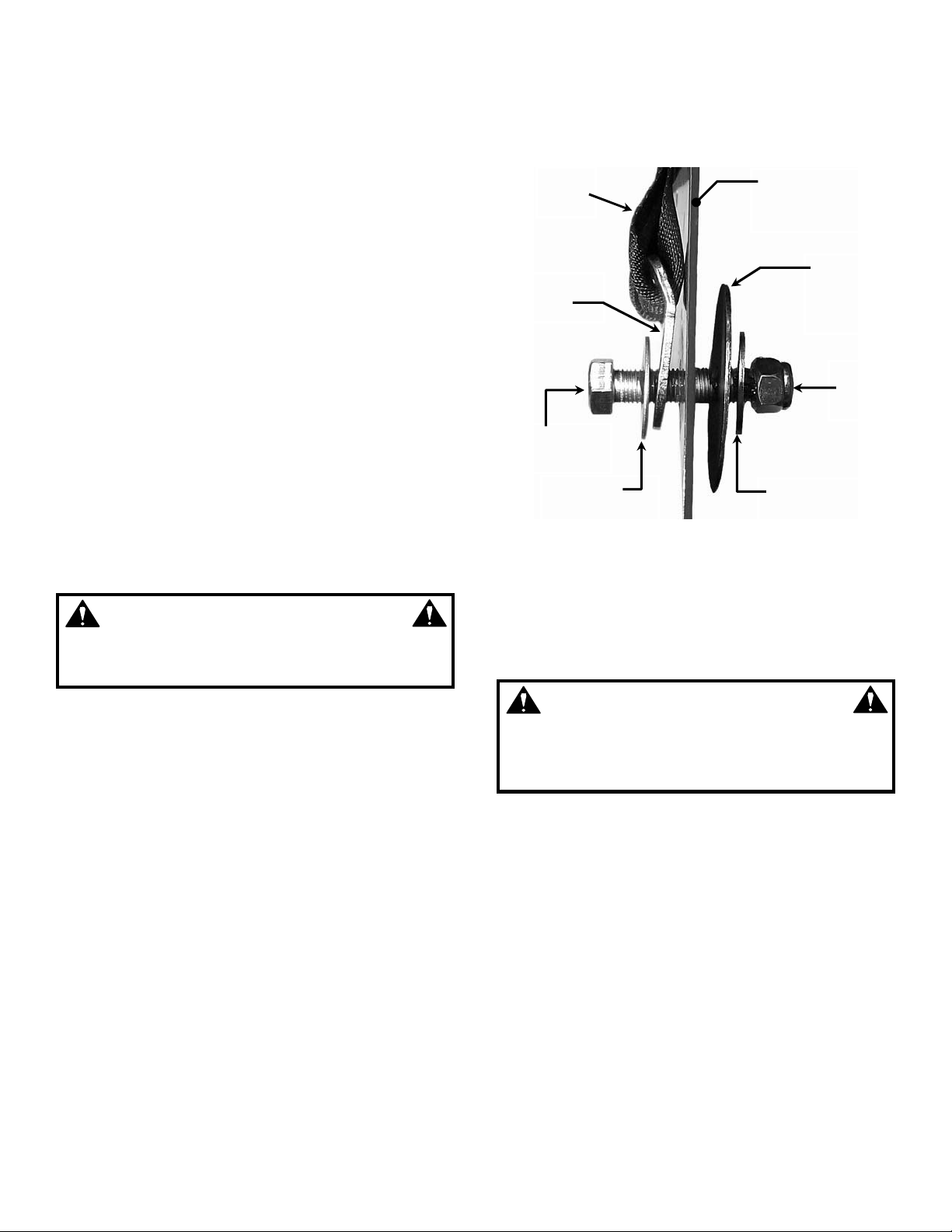
INSTALL SEAT BELTS
Mounting of seat belts is very important. Assemble
carefully using the sequ ence shown. The seat belt wi th
the latch plate is typically attached at the outside
mounting hole. The seat belt with th e buc k le is attac h e d
at the inside or m iddle mounting hole. T ighte n hard w ar e
to a snug rotating fit as described below.
IMPORTANT! The la rge 2 1/2” diameter f lat w ashers
must be installed on the in side surface of the seat
support structure. See Figure 1.3.
1. Remove the top t wo bolts from the fuel tank straps
and slide tank out. This will allow clearance to
install the bolt used to mount the right seat belt.
See Figure 1.4.
NOTE: tank straps r em ain loos e unti l ST EP 6, O perato r
Protective Structure installation has been completed.
2. Locate seat belts and hardware bag.
3. Place (1) 1/2” x 1 1/4“ d iameter flat washer on (1)
7/16-20 x 2” bolt. Inser t bolt with washer into seat
belt mounting plate. See Figure 1.3.
4. Insert bolt into hole in seat support. Place large
2 1/2” diameter flat washer over bolt against inside
surface of seat support.
5. Place (1) 1/2” x 1 1/4” flat washer on bolt. Install (1)
7/16-20 top lock nut.
BELT
PLATE
HEX BOLT
FLAT WASHER
SEAT SUPPORT
STRUCTURE
DIAMETER
FLAT
WASHER
NYLOC
NUT
FLAT WASHER
FIGURE 1.3
6. Tighten nut to a snug rotating fit. When properly
tightened the mounting bracket should be able to
rotate with some resistance to align properly with
seat position and size of operator, but not rattle.
7. Repeat for remaining three belts.
WARNING
Safe operation of machin e limits total occupants to
(2), one operator and one passenger. Seat belts
must be securely latched and adjusted to a snug fit
before starting or operating the machine.
Page 3
3
STEP 6
FUEL TANK
REMOVE TOP
HEAT
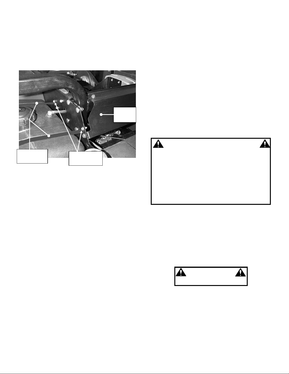
INSTALL OPERATOR PROTECTIVE
STRUCTURE (OPS)
The installation of the Operator Protective Structure
requires two people. The mounting hardware for the
OPS and seat belts must be properly torqued. Do Not
modify the OPS in an y way. Install the OPS with the
“WARNING” sign on the ri ght (passenger’s) side of the
machine.
SHIELD
STRAPS
1. Locate the mounting hardware – (12) 3/8-16 x 1”
round head carriage bolts and (12) 3/8-16 Nyloc
nuts. Place 6 of each in the left and right seat
support tray for easy access when attaching OPS
to frame.
2. Raise OPS to vertical pos ition and ori entate so that
the “WARNING” decal located on the side of the
OPS is on the passenger’s side of the mac hine.
3. Align holes in OPS with holes in frame. Get (1)
carriage bolt started on each side. NOTE: insert
bolts with head to wards outs ide of fram e as sho wn.
Secure with 3/8-16 Nyloc n ut. Do not tight en at this
time.
4. Install remainder of the bolts and secure eac h with
a Nyloc nut.
5. Torque ALL OPS mounting hardware to 30-35 ft-lb.
6. Reattach fuel tank straps. Tighten hardware
securely.
7. Attach heat shield to OPS using (2) 5/16-18 selftapping bolts. Do Not tighten at this time.
8. Attach heat shield to left and right f rame rails usin g
(2) 5/16-18 x 7/8” bolts and (2) 5/16-18 NyLoc nuts.
9. Tighten all heat shield hardware securely.
10. Reattach fuel tank straps. Tighten hardware
securely.
TWO BOLTS
FIGURE 1.4
STEP 7
ENGINE OIL AND TRANSMISSION FLUID
The engine oil an d transmission fluid m ust be checked
before operation.
1. Fill engine crankcase to proper level. Refer to
Engine Owner’s Manual for capacity and oil
specifications. Check with dipstick unthreaded.
2. Check transmis sion fluid leve l. Bring to f ull level as
necessary using MOBILFLUID 424 or equivalent.
Check with dipstick fully threaded.
STEP 8
ACTIVATE BATTERY
Battery is located under the operator’s seat. Remove
battery from com partm ent before acti vatin g or char gin g.
Activate and charge t he battery in well ventilated area
away from sparks and flame. Do Not smoke.
1. Remove battery from the battery compartment
before charging.
2. Place battery in a well ventilated area on a level
non-concrete surface.
WARNING
The electrolyte (acid) produces a highly explosive gas.
Keep all sparks, flame and fire away from area when
charging battery or when handling electrolyte or
battery. Electrolyte (acid) is a highly corrosiv e liquid.
Wear eye protection. Wash affected areas immediately
after hav ing e ye o r skin c ont act with e lect rol yte ( aci d).
Battery acid is corrosive. Rinse empty acid containers
with water and mutilate before discarding. If acid is
spilled on battery, bench, or clothing, etc., Fl ush with
clear water and neutralize with baking soda.
3. Remove battery ce ll c aps . Fill c e lls as r e quired with
electrolyte (purchased separately) to proper level.
Fill to 3/16” above cell plates. Filling battery with
electrolyte will bring the battery to 80% of full
charged state.
IMPORTANT: 3/16” above cell plates is the
recommend ed leve l. Never p lace an ything in ba tter y other
than specified electrolyte.
WARNING
DO NOT OVERFILL!
4. With cell caps removed, c onnect battery charger to
battery terminals; RED to positive (+) and BLACK
to negative (-) terminal.
5. Slow charge the batter y at 4 to 6 amps f or 2 hours
to bring the battery to full charge.
6. After charging, check level of electrolyte and add as
needed to bring level to 3/16” above cell plates.
7. Reinstall cell caps. Tighten securely to prevent
leakage.
Page 4
4
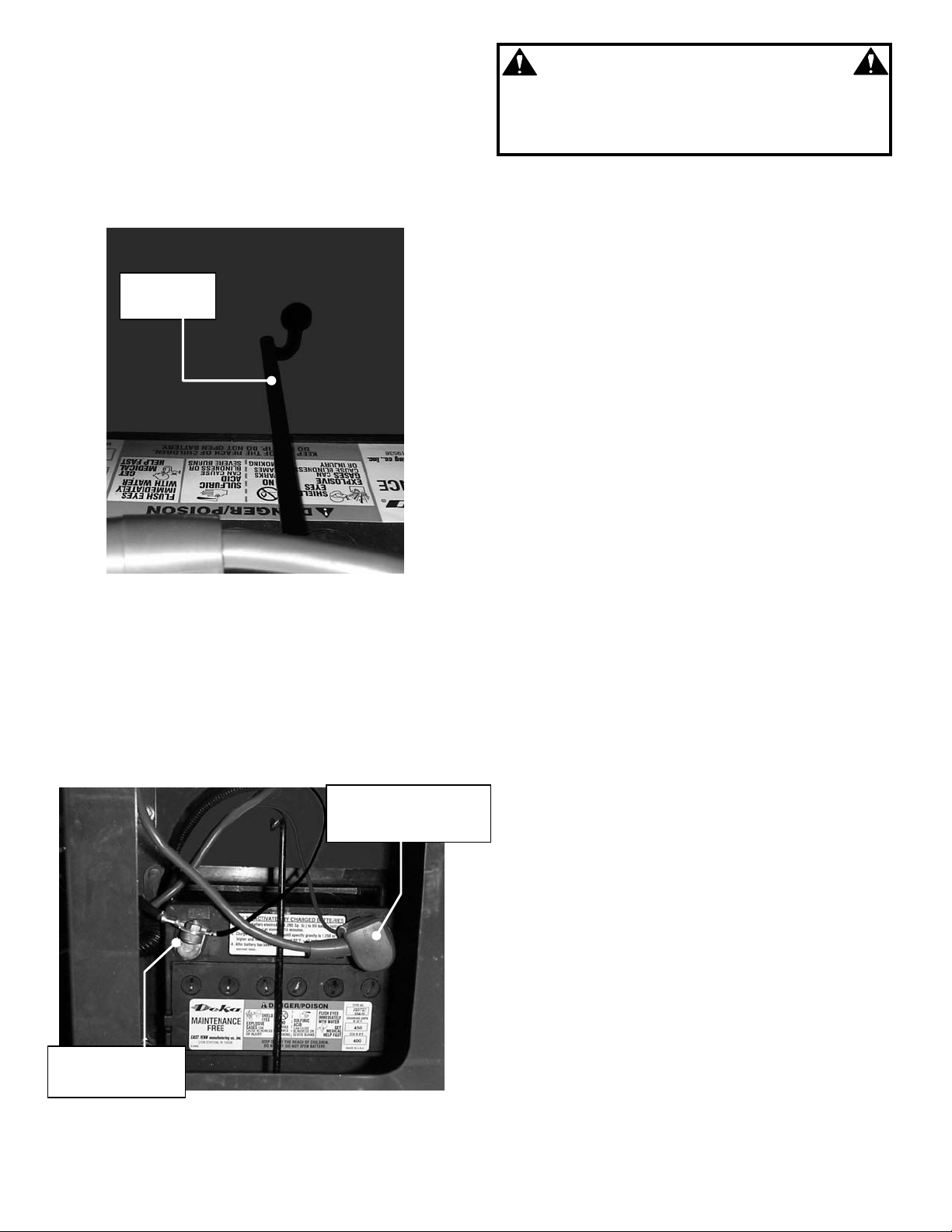
STEP 8 (Continued)
RETAINING
POSITIVE (+) CABLES
NEGATIVE (
-
)
ACTIVATE BATTERY
8. Thoroughly clean any spilled acid from battery.
Neutralize with Baking Soda and flush with large
quantity of water. Dry off battery.
9. Install battery into power unit. Place battery into
battery tray and secure i n place with retaining rod.
See Figure 1.5.
ROD
FIGURE 1.5
10. Attach battery cables to t erminals on the batt ery as
shown. See Figure 1.6. Co nnect positive ( +) cables
(red) first, from wiring harness to the positive
terminal (+) on battery and secure wit h nu t pro vi ded
in hardware bag. Connect negative (-) cables
(black) last, to negative ter minal (-) on battery and
secure. Apply a small amount of grease over
terminals to prevent corrosion. See Figure 1.6.
(RED) WITH TERMINAL
COVER
CABLES (BLACK)
FIGURE 1.6
WARNING
Shield the positive terminal with Terminal Cover
located on Positive Battery Cable. This prevents
metal from touching the positive terminal, which
could cause sparks.
STEP 9
INSTALL STEERING WHEEL
Make sure that the front tires are aligned perfectly
straight before installing the steer in g whee l.
1. Make sure that front tires are pointing straight
forward.
2. Slide foam cover over steering shaft.
3. Remove plastic cover from center of steering
wheel.
4. Orientate the steering wheel so that spokes are
horizontal and align splines.
5. Place washer and nu t on steer ing shaft. T orque nut
to 50-70 ft-lb.
6. Install plastic cover in center of steering wheel.
STEP 10
INSTALL O PERATOR ’S A ND PASS ENGER’ S
SEAT
Carefully complete the following steps to install the
seats.
1. Check seat bolts to insure hinge p late is tightened
securely to the bottom of the seat. See Figure 1.7.
2. Align hinge plate with seat/pedestal assem bly and
insert hinge rod.
IMPORTANT: Hinge rod must protrude past both
sides of the hinge plate and be positively retained
by the hair pin.
3. Insert hair pin full y into hinge rod. Hairpin mus t be
between hinge plate and s eat/pedest al to reta in rod
properly. See Figure 1.7.
4. Check for 5/16” flat washer under head of seat
knobs. Install washer, if missing, and tighten knobs
securely.
Page 5

5
STEP 10 (Continued)
1/2-13 X 3”
1/2-13 X 3 3/4”
NYLOC NUT
STRIKER
INSTALL O PERATOR ’S A ND PASS ENGER’ S
SEAT
(3) SEAT BOLTS
BOLT & 1/2-13
NYLOC NUT
HINGE ROD
HAIRPIN
FIGURE 1.7
STEP 11
ATTACH CARGO BED
Attach bed to pivots at rear of frame. A prop rod is
provided to support an empty cargo bed onl y in a rais e d
position.
1. Align brackets on bottom rear of car go bed with left
and right pivots loc ate d at rear of f r am e. See Fig ur e
1.8.
2. Insert (1) 1/2-13 x 3 3/4” b olt in to eac h left an d right
pivot and secure with 1/2-13 NyLoc nuts. Tighten
securely.
3. Attach prop rod t o bracket on bottom of cargo bed
using (1) 1/2-13 x 3” bolt a nd (1) 1/2-13 N yLoc nut.
Tighten to a snug rotating fit.
BOLT & 1/2-13
PROP ROD
FIGURE 1.8
STEP 12
ALIGN LATCH IF NECCESARY
Lower the Cargo bed slowl y until the latch contacts the
striker pin. The head of the striker pin s hould be inside
of the latch as shown in figure 1.9. If it is not aligned
correctly, loosen the bolts that attach the left and right
bed pivot brackets. Then, position the latch over the
striker pin as show n in figur e 1.9 and re- tighten th e bed
pivot bracket bolts.
PIN
FIGURE 1.9
LATCH ASSEMBLY
Page 6

6
DEALER CHECKLIST FOR
SNAPPER GROUNDS CRUISER
The following must be completed prior to sale. Refer to the previous pages in this setup instruction and in the
Operator’s manual for de tailed instructions. Revie w this checklist with purchaser. Ch eck () all items actually
performed. Purchaser and dealer must sign this form and the dealer retain the form for future reference.
SET-UP
_____ GEN E R A L I N SPECTI ON for loose, missing or damaged components. Rep aired as necessary.
_____ WHEEL LUG NUTS checked and torqued to 75 ft-lb.
_____ TIRE PRESSURE, FRONT AND REAR, adjusted to 15 PSI.
_____ SEAT BELTS installed, hardware tightened, and function of buckles verified.
_____ OPER ATOR P R OTECTI V E STR U C T U R E ins t a l led an d har d w are torqued to 5 0-70 f t - l b.
_____ BATTERY activated, charged and installed properly.
_____ STEERING WHEEL installed, alignment checked and nut torqued to 50-70 ft-lb.
_____ CA R GO B E D A N D P R O P R O D i n s t a l l e d and hardware tightened according to instructions.
_____ CARGO BED LATCH function verified.
_____ OPERATOR CONTROLS checked for binding and damage.
LUBRICATION AND FUEL
_____ ENGINE OIL added to bring level up to full mark (Refer to Engine Manual).
_____ TRANSMISSION FLUID checked and adjusted to full mark. (MOBILFLUID 424)
_____ AX L E C O U P L I N GS A N D S T E E R I N G KI N G P I N S g r e a se d . ( R e f e r t o O p e r a t o r ’ s manual).
_____ FUEL added to tank. (Refer to Engine Manual).
OPERATIONAL TEST
_____ ENGINE started, engine idles without dieing and runs smoothly.
_____ SAFETY INTERLOCKS checked and all function correctly. (Refer to Operator’s manual).
_____ TRANSMISSION shifts into forward and reverse without excessive grinding of gears.
_____ CLUTCH engages and accelerates smoothly and does not drag at idle.
_____ STEERING checked and functions properly.
_____ SE R V I C E B R AKE AND PARK BRAKE checked and both function properly. (Refer to Operator’s manual).
DEALER’S RECORDS & FINAL CHECK
_____ PERSONALLY HANDED Safety Instructions and Operator’s Manual to purchaser.
_____ INSTRUCTED purchaser to read and follow all instructions and warnings in Operator’s Manual.
_____ DEMONSTRATED proper starting procedure and operation of machine to purchaser.
_____ INSTRUCTED purchaser how to service air cleaner, maintain oil level (4-cycle).
_____ ASSISTED purchaser in completing Product Registration Card.
CONSUMER/OPERATOR PRODUCT REGISTRATION CARD
Purchase Date ________________ Model_____________________ Serial No. ____________________
Retailer’s Name _______________________________ Signature ________________________________
Address _________________________________ City _________________ State ______ Zip _____
MACHINE WILL BE USED COMMERCIALLY? _ YES ____ NO
Purchaser’s Name _____________________________ Signature ________________________________
Address _________________________________ City __________________ State______ Zip ______
IMPORTANT: This form is to be retained by the Dealer for future reference regarding
Warranty, proof of purchase, traceability for product recall or service, etc. Complete the
Product Registration Card and Mail to Customer Service Department at SNAPPER, P.O. BOX
1379, McDonough, Georgia, 30253.
INSTRUCTION No. 7-3574 (REV. 1, 8/25/00)
 Loading...