

Page 1
Safety Instructions & Operator’s Manual for
EUROPEAN
21” STEEL DECK
WALK MOWERS
SERIES 12
PROPELLED MODELS
EP216012
MODEL NUMBER EXPLANATION
E P 21 60 12
MODEL DESIGNATION SERIES DESIGNATION
SELF-PROPELLED ENGINE HORSE POWER
CUTTING WIDTH
E – European Model P – Self Propelled Model 12 - Series Designation
21 – 21” Cutting Width
60 – 6.0 HP (Engine Horse Power)
Thank you for buying a SNA PPER Produ ct! B efor e ope ratin g you r Walk B ehin d, r ead th is m an ual c areful ly a nd pay
particular attention to the “IMPORTANT SAFETY INSTRUCTIONS” on Pages 2 & 3. Remember that all power
equipment can be d an g e r ou s if us ed improperly. Al so ke ep in mind that SAFET Y req u ir e s ca r ef u l use in ac co rdance
with the operating instructions and common sense.
COPYRIGHT © 1999
SNAPPER INC.
ALL RIGHTS RESERVED
MANUAL No. 7-3144 (I.R. 8/20/99)
Page 2

2
IMPORTANT SAFETY INSTRUCTIONS
WARNING: This powerful cutting machine is capable of amputating hands and feet and can throw objects that
can cause injury and damage! Failure to comply with the following SAFETY instructions could result in serious
injury or death to the operator or other persons. The owner of the machine must understand these instructions
and must allow only persons who understand these instructions to operate machine . Each person operating
the machine must be of sound mind and body and must not be under the influence of any substance, which
might impair vision, dexterity or judgment. If you have any questions pertaining to your machine which your
dealer cannot answer to your satisfaction, call or write the Customer Service Department at SNAPPER,
McDonough, Georgia 30253. Phone: (1-800-935-2967).
PROTECTION FOR CHILDREN
Tragic accidents can occur if the operator is not
alert to the presence of children. Children are often
attracted to the machine and the mowing activity.
Never assume that children will remain where you
last saw them.
1. KEEP children out of the mowing area and
under the watchful care of a responsible adult.
2. DO NOT allow children in yard w hen machine i s
operated and turn machine OFF if anyone
enters the area.
3. DO NOT allow pre-teenage children to operate
machine.
4. ALLOW only responsible adults & teenagers
with mature judgment under close adult
supervision to operate machine.
5. DO NOT pull mower backwards unless
absolutely necessary. LOOK and SEE behind
and down for children, pets and hazards before
and while backing.
6. USE EXTRA CARE when approaching blind
corners, shrubs, trees, or other objects that
may obscure vision.
SLOPE OPERATION
1. Slopes are a major fact or related to slip and f all
accidents, which can result in severe inju ry. All
slopes require extra caution. If you feel une asy
on a slope, DO NOT mow it.
2. Mow across slopes, never up-and-down.
Exercise extreme CAUTION when changing
directions on slopes. DO NOT mow steep
slopes or other areas where stabilit y or traction
is in doubt.
3. Use extra care with crass catchers or other
attachments; these affect the handling and the
stability of the machine.
PREPARATION
1. Read, understand, and follow instructions and
warnings in this manual and on the mower,
engine and attachments. Know the controls and
the proper use of the mower before starting.
2. Only mature, responsible persons shall operate
the machine and only after proper instruction.
PREPARATION
(Continued From Previous Column)
3. Data indicates that operators ag e 60 and above,
are involved in a large percentage of mowerrelated injuries. These operators should
evaluate their ability to operate the mower
safely enough to protect themselves and others
from serious injury.
4. Handle fuel wit h extra car e. Fuels are f lammable
and vapors are explosiv e. Use o nl y an app rov ed
fuel container. DO NOT remov e fuel cap or add
fuel with engine running. Add fuel outdoors
only with engine stopped and cool. Clean
spilled fuel and oil from machine. DO NOT
smoke.
5. Check the area to be mowed and remove all
objects such as toys, wire, rocks, limbs and
other objects that could cause injury if thrown
by blade or interfere with mow ing. Also note the
location of holes, stumps, and other possible
hazards.
6. Keep people and pets out of the mowing area.
Immediately, STOP Blade, Stop engine and Stop
mower if anyone enters the area.
7. Check shields, deflectors, switches, blade
controls and other saf ety devices frequ ently for
proper operation and location.
8. Make sure all safety decals are clearly legible.
Replace if damaged.
9. Protect yourself when mowing and wear safety
glasses, long pants and substantial footwear.
DO NOT mow barefooted or with sandals.
10. Know how to STOP blade and engine quickly in
preparation for emergencies.
11. Use extra care when loading or unloading the
machine into a trailer or truck.
12. Check grass catcher components frequently for
signs of wear or deterioration and replace as
needed to prevent injury from thrown objects
going through weak or torn spots.
Page 3

3
IMPORTANT SAFETY INSTRUCTIONS
OPERATION
1. DO NOT put hands or feet near or under rotating
parts. Keep clear of discharge area while engine is
running.
2. STOP engine when crossing gravel drives, walks, or
roads, and under any conditions where thrown
objects might be a hazard.
3. Mow only in daylight or good artificial light.
4. DO NOT operate mower while under the in flue nce of
alcohol or drugs.
5. After striking a foreign object or if mower vibrates
abnormally, STOP the engine, disconnect and
secure spark plug wire. Inspect the mower for any
damage and repair t he damage .
6. DO NOT mow near drop offs, ditches or
embankments. Operator could lose footing or
balance.
7. STAY ALERT for holes and other hidden
hazards. Tall grass can hide obstacles. Keep
away from ditches, washouts, culverts, fences
and protruding objects.
8. DO NOT mow on wet grass. Always be su re of
your footing. Keep a firm hold on the handle
and walk, never run. Slipping could cause
injury.
9. DO NOT leave the machine with the engine
running. STOP BLADE and STOP ENGINE
before leaving the operators position for any
reason.
10. Before cleaning, repairing or inspecting make
certain engine, blade and all moving parts have
STOPPED. Disconnect and secure spark plug
wire away from plug to prevent accidental
starting.
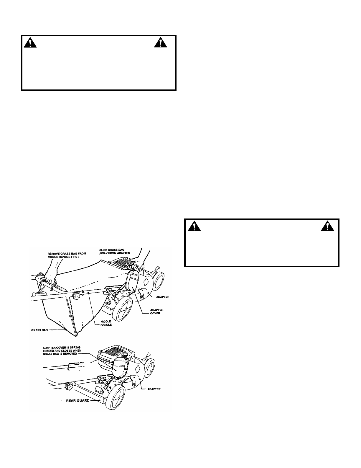
11. STOP eng ine and wait until the blade comes to
complete STOP before removing grass bag
and/or clearing grass.
12. DO NOT operate mower with out the ent ire grass
catcher or guards in place. DO NOT point
discharge at people, passing cars, windows or
doors.
13. Slow down before turning.
14. Watch out for traffic when near or crossing
roadways.
15. DO NOT operate engine in enclosed areas.
Engine exhaust gases contain carbon
monoxide, a deadly poison.
MAINTENANCE AND STORAGE
1. DO NOT store mower or fuel container inside
where fumes may re ach a n o pen flame, spark or
pilot light such as in a water heater, furnace,
clothes dryer or other gas appliance. Allow
engine to cool before storing machine in an
enclosure. Store fuel container out of reach of
children in a well ventilated, unoccupied
building.
2. Keep mower and engine f ree of g rass, leav es or
excess grease to reduce f ire hazard and engine
overheating.
3. When draining fuel tank, drain fuel into an
approved container outdoors and away from
open flame.
4. Keep all bolts, especia lly blade bolts, nuts and
screws properly tight . Check that all cot ter pins
are in proper position.
5. Always provide adequate ventilation when
running engine. Engine exhaust gases contain
carbon monoxide, a deadly poison.
6. Service engine and make adjustments only
when engine is stopped. Removed spark plug
wire from spark plug and secur e wire away from
spark plug to prevent accidental starting.
7. DO NOT change engine governor speed
settings or overspeed engine.
8. Check grass bag assembly frequently for wear
or deterioration to avoid thrown objects and
exposure to moving parts. Replace with new
bag if loose seam s or tea rs are evident. Replace
slider or bag adapter if broken or cracked.
9. Mower blades are sharp and can cut. Wrap the
blades or wear heavy leather gloves and use
CAUTION when handling them.
10. DO NOT test for spark by grounding spark plug
next to spark plug hole; spark plug could ignite
gas exiting engine.
11. Have machine serviced by an authorized
SNAPPER dealer at least once a year and have
the dealer install any new safety devices.
12. Use only genuine SNAPPER replacement parts
to assure that original standards are
maintained.
Page 4

4
TABLE OF CONTENTS
IMPORTANT SAFETY INSTRUCTIONS..............................................2 - 3
TABLE OF CONTENTS............................................................................4
SECTION 1 - FAMILIARIZATION.............................................................5
SECTION 2 - OPERATING INSTRUCTIONS.........................................6-8
Pre-start Checklist............................................................................................... 6
Starting & Stopping Engine & Blades................................................................ 6
Starting & Stopping Wheel Drive ....................................................................... 7
Handle Height Adjustment.................................................................................. 7
Cutting Height Adjustment ................................................................................ .7
Recycling Operation............................................................................................8
Installation of Grass Catcher..............................................................................8
SECTION 3 - MAINTENANCE INSTRUCTIONS .................................9-10
Change Engine Oil...............................................................................................9
Check Transmission Grease ......................................................................... 9-10
Check Mower Blade........................................................................................... 10
Check Engine Drive Belt ................................................................................... 10
Check Transmission Poly-V Belt...................................................................... 10
Service - Annually.............................................................................................. 10
Engine.............................................................................................................. 10
Air Filter...........................................................................................................10
Engine Oil........................................................................................................10
Storage Procedure............................................................................................. 10
SECTION 4 - ADJUSTMENTS AND REPAIR....................................11-17
Mower Blade Replacement ............................................................................... 11
Blade Sharpening .........................................................................................11-12
Wheel Drive Control Adjustment...................................................................... 12
Driven and Drive Disc Service.......................................................................... 12
Cleaning Drive Disc and Driven Disc ........................................................... 13
Drive Spring Repair/Replacement ................................................................ 13
Driven Disc Adjustment............................................................................13-14
Driven Disc Replacement ......................................................................... 14-15
Driven Disc Bearing Replacement................................................................ 15
Hex Shaft Bearing Replacement ................................................................... 16
Belt Service ........................................................................................................ 16
Engine Drive Belt Replacement ............................................................... 16-17
Transmission Poly-V Belt Replacement....................................................... 17
TROUBLESHOOTING ............................................................................ 18
SERVICE SCHEDULE ............................................................................ 19
Maintenance/Replacement Parts...................................................................... 19
DECAL IDENTIFICATION..................................................................20-21
WARRANTY............................................................................................ 22
Page 5
5
Section 1 - FAMILIARIZATION
FIGURE 1.1
1.1 INTRODUCTION
This manual has been prepar ed for the operators of
the SNAPPER WALK BEHIND MOWERS. Its
purpose, aside from recommending operating and
routine service requirements, is to promote safety
through the use of accepted operating practices.
Read, Understand and Follow the “IMPORTANT
SAFETY INSTRUCTIONS” on Pages 2 & 3 of this
manual and all s afety messages on the mower a nd
attachments before operating the mower.
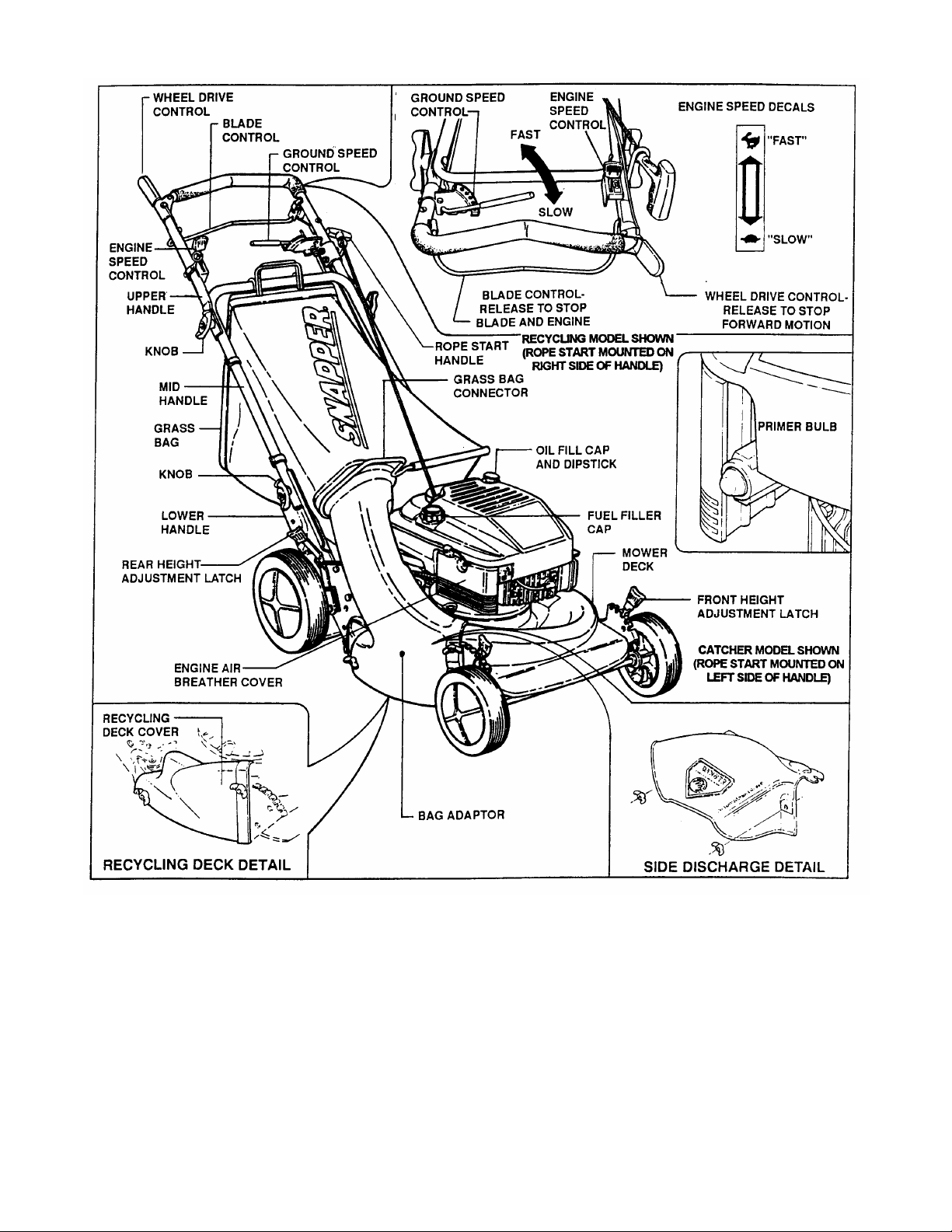
1.2 NOMENCLATURE
The nomenclature dra wing above, F igure 1.1, sho ws
the essential parts of the SNAP PER WALK BEHIND
MOWERS. It is recommended that all operators of
the mower become thoroughly familiar with the
controls, parts and operation of the mower before
operating. Specific details involving the engine are
found in the separat e eng ine owner’s manua l. Stud y
these manuals before operating and keep both
handy for future reference.
Page 6
6
Section 2 - OPERATING INSTRUCTIONS
BLADE
WHEEL DRIVE
RECYCLING MODEL SHOWN
CATCHER MODEL SHOWN
BLADE
WHEEL
ENGINE SPEED
2.1 PRE-START CHECK LIST
Make the following checks and perform the service
required before ea ch start -up.
2.1.1. Check guards, deflectors, grass bag, adapter
and covers to m ake sure all are i n place and secur ely
tightened.
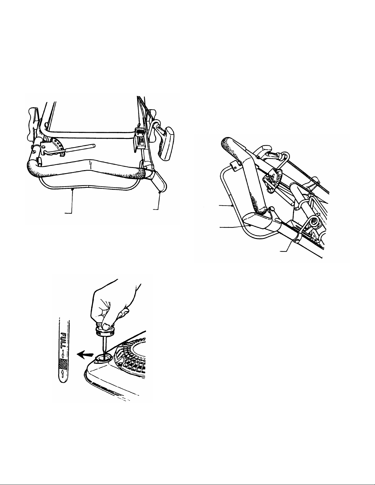
2.1.2. Check blade control and wheel drive control
to insure they work freely. See Figure 2.1.
(ROPE START MOUNTED ON
RIGHT SIDE OF HANDLE)
2.1.6. Clean exterior surfaces of cutting deck and
engine of any accumulati on of spilled f uel, dirt, gr ass,
oil, etc. Keep engine air intake screen and cooling
fins clear at all times.
2.2 STARTING & OPERATION
2.2.1. ENGINE & BLADE
(Primer Models)
1. M ove eng ine spee d contr ol to th e “Fast” (Rabbit)
position. See Figure 2.3.
NOTE: Stop the engine (and blade) by releasing the
blade control.
(ROPE START MOUNT ED
ON LEFT SIDE OF HAN DLE)
CONTROL
CONTROL
FIGURE 2.1
2.1.3. Check cutting height. Adjust to desired height.
2.1.4. Check engine oil and add oil as needed to bring
level up to the full mark. Refer to Engine Owner’s
Manual for oil specificatio ns. See Fig ure 2.2.
FIGURE 2.2
2.1.5. Add fuel to tank after pushing the mower
outside where fumes c an safely dissi pate. Mak e sure
cap is tightened after refueling. Refer to Engine
Owners Manual for specifications.
CONTROL
DRIVE
CONTROL
CONTROL
(SHOWN IN FAST
FIGURE 2.3
2. Push primer button three times to start a cold
engine. NOTE: Do not use primer button to start
warm engine.
3. Pull blade control against handle.
4. Pull rope start handle to crank engine.
5. After engine starts, allow a brief warm-up until
engine runs smooth.
Page 7
7
Section 2 - OPERATING INSTRUCTIONS
MOVE GROUND
RECYCLING MODEL SHOWN
(SLOW)
(FAST)
POSITION
WHEEL DRIVE
BLADE
SIXTH
LOOSEN LOWER
LOWER
LOWEST CUTTING
HEIGHT
1
HIGHEST
6
1
5 6
LATCH
2.2.2. PROPELLING MOWER
(Self Propelled Models Only)
1. Move ground speed c ontrol to the desir ed speed
position. See Figure 2.4.
2. Start engine. Refer to Section “Starting &
Operation”.
3. Move wheel drive control against handle to
engage wheel drive and propel mower forward.
Forward speed can be adjus ted while the mower is
moving by changing position of the ground speed
control. See Figure 2.4.
SPEED CONTROL TO
DESIRED POSIT ION
SIXTH SPEED
(ROPE START MOUNTED ON
RIGHT SIDE OF HANDLE)
2. Move upper mower handle up or do wn until the
desired position is achie ved.
3. T ighten the lower nuts on each lower handle to
maintain desired positi on.
STOP engine and mower blade by releasing the blade
control before adjusting cutting height or handle
height.
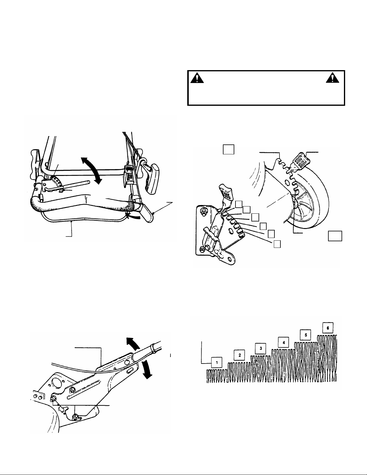
2.5 CUTTING HEIGHT ADJUSTMENT
1. Pul l the height adjusting lat ch outward a nd move
to desired cutting height. See Figure 2.6.
WARNING
LATCH
FIRST
CONTROL
FIRST SPEED
POSITION
CONTROL
FIGURE 2.4
2.3 STOPPING
Stop engine and blade by releasing the blade
control. Stop forward m otion of mower by releasing
the wheel drive control.
2.4 HANDLE HEIGHT ADJUSTMENT
The height of the m ower hand le can be adjusted as
follows:
1. Loosen the lower nuts on each lower handle as
shown in Figure 2.5.
HIGHER
HANDLE
2
3
4
CUTTING
HEIGHT
FIGURE 2.6
2. Set all wheels at the same cutting height. The
highest cutting position is Notch 6. The lowest
cutting position is Notch 1. See Figure 2.7.
POSITIONS
NUTS ON EACH
LOWER HANDLE
FIGURE 2.5
LOWER
CUTTING HEIGHT SETTINGS
FIGURE 2.7
Page 8
8
Section 2 - OPERATING INSTRUCTIONS
WARNING
DO NOT attempt any maintenance, adjustments or
service with engine and blade running. STOP engine
and blade. Disconnect spark plug wire and secure
away from spark plug. Engine and components are
HOT. Avoid serious burns, allow sufficient time for all
components to cool.
2.6 RECYCLING OPERATION
NOTE: For best recycling results , cut up to a maximum of
1/3 of grass blade length and r ecycle ONLY when grass
is dry.
1. Set all wheels in the highest cutting position
(Notch 6).
2. Move engine speed control to “FAST” (Rabbit)
position.
3. Move ground speed control to slowest speed
setting.
4. Proceed mowing slowly. If grass is very dense,
lower each rear wheel latch one notch lower than
the front wheel latches to improve recycling
performance.
2.7 INSTALLATION of GRASS CATCHER
Install gras s catcher by slidi ng connector over fl ange
of adapter. Attach grass bag h oo ks ove r middle handle
cross bar. See Figu re 2 .8.
FIGURE 2.8
DO NOT operate without entire Grass Catcher or
guard in place. Grass Catcher components are
subject to deterioration during normal use. Inspect
frequently and replace worn or damaged
components immediately.
WARNING
Page 9

9
Section 3 - MAINTENANCE
3.1 INTRODUCTION
To retain the quality of the mower, use genuine
SNAPPER replacem ent parts only. Contact a local
SNAPPER dealer for parts and service assistance.
For the correct part or information for a particular
mower, always mention model and serial number.
3.2 SERVICE - AFTER FIRST 5 HOURS
3.2.1. CHANGE ENGINE OIL
WARNING
DO NOT attempt any maintenance, adjustments or
service with engine and blade running. STOP engine
and blade. Disconnect spark plug wire and secure
away from spark plug. Engine and components are
HOT. Avoid serious burns, allow sufficient time for all
components to cool.
1. Refer to Engine Manual for proper oil
specifications and procedures.
2. For simplest/cleanest oil change, loosen lower
handle wing nuts and stand mower up on lower
handle as shown in Figure 3.1. Drain oil through
dipstick tube into a container.
FIGURE 3.1
3.2.2. CHECK GREASE LEVEL IN TRANSMISSION
1. Remove transmission fill plug. Roll machine
forward or backward while looking down into plug
hole.
2. If liquid
(the small gear below the plug hole), add an
amount, to cover gear , of S napper “00” grease. See
Figure 3.2.
FILL PLUG
NOTE: Snapper “00” Grease (Part No. 2-9443) is av ailable
at your SNAPPER dealer.
grease IS NOT visible on the input g ear
FIGURE 3.2
(Continued on Next Page)
Page 10
10
Section 3 – MAINTENANCE
RECOMMENDED
3.2.2. CHECK GREASE LEVEL IN TRANSMISSION
(Continue d fr om pr e vious page )
NOTE: Do not spill grease or oil on surface of drive
disc. See Figure 3.3.
3. Reinstall transmission plug.
4. Check grease level after each 25 hours of
operation.
KEEP DRIVE DISC CLEAN !
3.2.4 CHECK ENGINE DRIVE BELT
1. Visually check engine drive belt for cracking,
fr aying, severed or be lt strands exposed. If wo rn or
damaged, replace belt before operating mower.
3.2.5 CHECK TRANSMISSION POLY-V BELT
1. Visually check poly-v belt for cracking, fraying,
severed or belt strands exposed. If worn or
damaged, replace belt before operating mower.
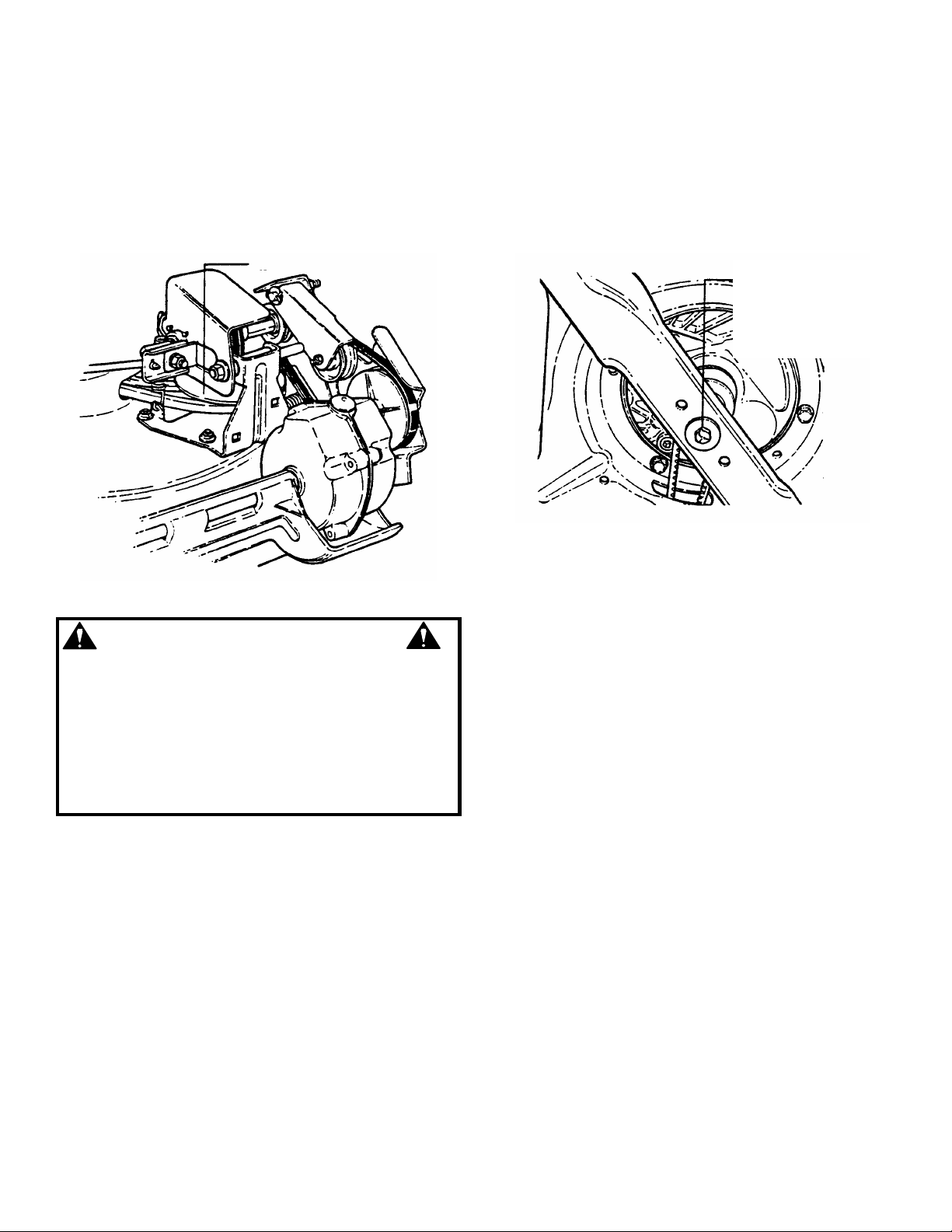
BLADE RETAINING
CAP SCREW
TORQUE VALUE
SHOULD BE 30 TO
40 FT. LBS.
FIGURE 3.3
WARNING
DO NOT attempt any maintenance, adjustments or
service with engine and blade running. STOP engine
and blade. Disconnect spark plug wire and secure
away from spark plug. Engine and components are
HOT. Avoid serious burns, allow sufficient time for
all components to cool. Wear heavy leather gloves
when handling or working around cutting blades.
Blades are extremely sharp and can cause severe
injury.
IMPORTANT: DO NOT tip machine with carburetor or
spark plug down. Oil fr om crankcase will saturate the air
filter and cause the engi ne to be hard to start or not start
at all. If contaminatio n does oc c ur , the air filter will have to
be replaced.
3.2.3 CHECK MOWER BLADE
1. Disconnect spark plug wire and secure end
away from plug.
2. Tilt mower up on its rear wheels for access to
the blade cap screw. Do not tilt mower with spark
plug or carburetor down. See Figure 3.4.
3. Check torque of blade retaining cap screw.
Recommended torque should be 30 to 40 ft. lbs.
See Figure 3.4.
4. Check blade for sharpness, wear and damage.
Refer to Section “Blade Wear Limits”.
FIGURE 3.4
3.3 SERVICE - ANNUALLY
Perform all maintenance as described in the “Service
Schedule” section of thi s manual .
3.3.1. Engine
Service engine a c cording t o e ngin e owne r’ s manu al.
3.3.2. Air Filter
Refer to engine owner’s manual for service instructions.
3.3.3. Engine Oil
Refer to engine owner’s manual for service
instructions.
3.4 STORAGE PROCEDURE
Refer to the Engine Owner’s Manual for directions
regarding engine storage preparations. Prepare the
mower for “end of season” storage as follows:
1. Drain fuel from fuel tank and let engine run until
all fuel is out of the carburetor.
2. Disconnect and remove the spark plug wire
away from spark plug before any other
preparations are made!
3. Tape all openings closed to prevent spraying
water into exhaust or air intakes during washing.
4. Tilt mower up on its rear whee ls and thoroughl y
clean the underside of the dec k. Do not tilt mower
with spark plug or carbure tor down. Scrape away
any accumulation of grass with a putty k nife and or
wire brush.
5. Lubricate all expos ed metal with a light coating
of oil to prevent corrosion.
6. On self-propelled models, loosen wing nuts on
ground speed control rod before folding handles.
7. Loosen hand le knobs. Caref ully fold the handles
forward, “flexing” the control cables to prevent cable
damage.
8. Store the mower in a shed or other dry area,
protected from weather.
Page 11

11
Section 4 - REPAIR & ADJUSTMENTS
BLADE
MAKE SURE THAT
CONE WASHER
WEAR LIMIT
DANGEROUS CONDITION !
WEAR LIMIT.
DANGEROUS !
WARNING
DO NOT attempt any maintenance, adjustments or
service with engine and blade running. STOP engine
and blade. Disconnect spark plug wire and secure
away from spark plug. Engine and components are
HOT. Avoid serious burns, allow sufficient time for all
components to cool. Wear heavy leather gloves when
handling or working around cutting blades. Blades
are extremely sharp and can cause severe injury.
4.1 MOWER BLADE REPLACEMENT
4.1.1. STANDARD BLADE WEAR LIMIT
1. Inspect blade frequently for signs of excessive
wear or da ma ge . See Figure 4.1.
4.1.1A. NINJA BLADE WEAR LIMIT
1A. Inspect blade frequently for signs of
excessive wear or damage. See Figure 4.2.
NEW BLADE
NEW BLADE
(NOTCH STARTS)
DO NOT USE ON MOWER !
REPLACE WITH NEW
BLADE.
FIGURE 4.1
CRACKS OR
NOTCHES
BEGIN TO
APPEAR ON TIP
2. Replace the blade if it is badly chipped, bent,
noticeably out of bal ance or has cracks or notch in
either tip. See Figure 4.1 & 4.1A. Re place with new
blade.
DO NOT use a cutting blade that shows signs of
excessive wear or damage. Refer to Section
“MOWER BLADE REPLACEMENT” for proper blade
inspection and service procedures.
4.1.2. BLADE SHARPENING
1. Disconnect s park plug wire and secur e end awa y
from plug.
IMPORTANT: DO NOT tip machine with carburetor or
spark plug down. Oil f rom crankcase will saturate the air
filter and cause the engine to be hard to start or not s tart
at all. If contamination d oes occ ur, the air filter will have to
be replaced.
2. Tilt mower up on its rear wheels. Do not tilt
mower with spark plug or carburetor down.
3. Remove blade. See Figure 4.3.
WARNING
HUB
FLANGE
BLADE
(Concave Side Up)
BLADE HUB IS
SEATED
BETWEEN
FLANGES
DO NOT USE A BLADE IN
THIS CONDITION !
FIGURE 4.2
CAPSCREW
FIGURE 4.3
Page 12

12
Section 4 - REPAIR & ADJUSTMENTS
CLUTCH CABLE
VINYL S
PRING
1/16” TO 1/8”
UPPER
SPRING
LOWER
CLUTCH CABLE
CLUTCH CABLE EYE
DO NOT SHARPEN
END VIEW OF
WARNING
DO NOT attempt any maintenance, adjustments or
service with engine and blade running. STOP engine
and blade. Disconnect spark plug wire and secure
away from spark plug. Engine and components are
HOT. Avoid serious burns, allow sufficient time for all
components to cool.
4. Sharp en b lad e on a gr ind in g whee l at an angle of
22 to 28 degrees. DO NO T sharpen blade beyond
original cutting edge. See Figure 4.4.
BEYOND ORIGINAL
CUTTING EDGE
22-28º
CLEARANCE
SPRING
EYE
SPRING HOOK
CABLE
BLADE TIP
BLADE ASSEMBLY
ORIGINAL CUTTING EDGE
FIGURE 4.4
5. Check blade for balance. If necessary, correct
balance by grinding heav y end of blade.
6. Reins tall blade. See Figure 4.1. Check torque of
blade retaining cap screw. Recommended torque
should be 30 to 40 ft. lbs.
NOTE: The following sections 4.2 through
4.4 are for self-propelled models only.
4.2 WHEEL DRIVE CONTROL ADJUSTMENT
1. The wheel drive control is properly adjusted
when there is 1/16” to 1/8” clearance between the
inside of the spring hook and the ins ide of the clutch
cable eye with the wheel driv e control r eleas ed. Se e
Figure 4.5.
SPRING
FIGURE 4.5
2. To adjust, unhook upper spring from cable eye
and rotate spring in direction required to extend or
shorten spring length.
3. Rehook upper spring to cable eye and check
clearance. Repeat procedure if required.
NOTE: The vinyl spring cover should be kept over the
spring at all times except for adjustments.
4. If the wheel drive con trol fails to re turn quick ly to
the “OFF” position when re leased, ch eck for binding
at the cable holdings locate d on the side of the right
handle. The upper c lip should be located 2” be low
the upper knob; the lower clip should be 4” above
the lower knob. The cable should slide freely with
the clips installed at these locations.
Page 13

13
Section 4 - REPAIR & ADJUSTMENTS
USE
DRIVE
SPRING
MOVE GROUND
REYCLING MODEL SHOWN
SIXTH SPEED
SIXTH
FIRST SPEED
POSITION
DRIVEN DISC &
RUBBER RING
POLY
-
V
DRIVE
ENGINE
DRIVE
WARNING
DO NOT attempt any maintenance, adjustments or
service with engine and blade running. STOP engine
and blade. Disconnect spark plug wire and secure
away from spark plug. Engine and components are
HOT. Avoid serious burns, allow sufficient time for all
components to cool.
4.3 DRIVEN DISC SERVICE
If the mower does not propel itself properly, See
Figure 4.6. Check for the following problems:
BELT
SPRING
DRIVE
BELT
DISC
FIGURE 4.6
1. Grease on drive disc causing slippage.
2. Broken or disconnected drive spring.
3. Driven disc is out of adjustment.
4. Drive n d isc rubber ring is wor n - do es n ot c ont ac t
drive disc properly.
5. Worn Poly-V Belt or engine drive belt.
NOTE: If any of the above (1 thru 5) are causing
problems, service as follows:
4.3.1. Cleaning Drive Disc & Driven Disc.
If oil or grease on the drive disc or driven disc is
causing slippage, clean discs as follows:
1. Wipe away any oil or grease with a clean cloth.
2. Use either an approved grease solvent or hot,
soapy water to clean drive disc or driven disc.
3. Rinse components with clean water.
4. Dry components with a clean cloth.
4.3.2. Drive Spring Repair/Replacement
If drive spri ng is loose, rec onnect as sho wn in Figure
4.7. If spring is broken, replace with new spring.
IMPORTANT: If machine drive system continues
slipping see Trouble Shooting section.
4.3.3. DRIVEN DISC ADJUSTMENT
If the drive disc an d driven disc are clean and the
mower drive is sti ll s l ipp in g, adj us t the dr iv en d is c as
follows:
1. Place ground speed control in the number six
speed position. See Figure 4.8.
SPEED CONTROL TO
SIX SPEED POSITIO N
NEEDLE
NOSE
PLIERS TO
INSTALL
DRIVE
SPRING
FIGURE 4.7
(ROPE START MOUNTED ON
RIGHT SIDE OF HANDLE)
POSITION
FIRST
FIGURE 4.8
Page 14

14
Section 4 - REPAIR & ADJUSTMENTS
1/8” MEASUREMENT TO
DRIVE
SLIDE DRIVEN
TRANSFER
ROD
CONNECTOR
OUTSIDE
CONNECTOR
SPEED CONTROL
TRANSFER
DRIVEN DISC
DRIVE
DRIVEN DISC
TRANSFE
R
CONNECTOR
WARNING
DO NOT attempt any maintenance, adjustments or
service with engine and blade running. STOP engine
and blade. Disconnect spark plug wire and secure
away from spark plug. Engine and components are
HOT. Avoid serious burns, allow sufficient time for
all components to cool.
4.3.3. DRIVEN DISC ADJUSTMENT
(Continued From Previous Page)
2. Remove driven disc spring from driven disc
assembly. Loosen connector hex nut. See Figu re 4.9.
ASSEMBLY
DISC ASSEMBLY
TOWARD OUTS IDE
EDGE
OUTSIDE EDGE OF DRIVE
DISC
DISC
SPRING
ROD
CONNECTOR
DISC
HEX NUT
FIGURE 4.9
3. Slide driven disc assembly over to 1/8” from
outside edge of drive disc. Maintaining the 1/8”
measurement, remove any looseness from the
linkage. This can be done by holding the transfer rod
and applying pressure to the left (as viewed from
operators p osition). Th en retighten t he connect or hex
nut securely. See Figure 4.10. Move ground speed
control to the first speed position, then back to the
sixth speed position. Rech eck the 1/8” meas urement
described previously. Reins tall driven disc s pring to
driven disc assembly .
HEX NUT
CONNECTOR
EDGE
FIGURE 4.10
4.3.4. Replacing Rubber Driven Disc Ring
If the rubber ring is badly chunked or worn down to
within 1/16” of the metal r im of the dri ven disc hub, it
must be replaced. Install new rubbe r ring as follows:
1. Us ing a small flat blade sc rewdriver, free the c lip
from the transfer rod. Then remove the transfer rod
from the clip and the speed control rod. See Figure
4.11.
CLIP
ROD
ROD
FIGURE 4.11
(Continued On Next Page)
Page 15

15
Section 4 - REPAIR & ADJUSTMENTS
SHIM
SNAP
THRUST
BEARING
DRIVEN DISC
DRIVEN DISC
RUBBER
DRIVE DISC
ASSEMBLY
MACHINE
RUBBER
WARNING
DO NOT attempt any maintenance, adjustments or
service with engine and blade running. STOP engine
and blade. Disconnect spark plug wire and secure
away from spark plug. Engine and components are
HOT. Avoid serious burns, allow sufficient time for
all components to cool.
4.3.4. Replacing Rubber Driven Disc Ring
(Continued From Previous Page)
2. Using nee dle nose pliers , unhook the dr ive spring
and slide the driven disc ass embly off the hex s haft.
See Figure 4.12.
3. Rem ove the fi ve mach ine scre ws and plate , which
secure the rubber ring to the driven disc hub. See
Figure 4.13.
4. Install new rubber ring.
5. Reverse above procedures for reassembly and
installation.
4.3.5. Replacing Bearing In Driven Disc Assembly
If the driven disc bearing fails, remove the driven
disc assembly and replace bearing as follows:
1. Us ing a small flat blade sc rewdriver, free the c lip
from the transfer rod. Then remove the transfer rod
from the clip and the speed control rod. See Figure
4.11.
2. Us ing needle nos e pliers, unho ok the drive spr ing
and slide the driven disc ass embly off the hex s haft.
See Figure 4.12.
3. Rem ove snap ring that secures driven disc hub
to thrust plate. See Figure 4.14.
PLATE
REMOVE FOUR
MACHINE
SCREWS
WASHER
RING
HUB
SCREWS
FIGURE 4.12
PLATE
DRIVEN DISC HUB
RING
FIGURE 4.13
PLATE
DISC
FIGURE 4.14
4. Slide the hub assembly out of the bearing.
5. Remove the four screws.
6. Remove bearing and replace with new bearing.
7. Reassemble components in reverse order.
Page 16

16
Section 4 - REPAIR & ADJUSTMENTS
3/8”
BALL BEARING
RIGHT REAR
WHEEL BRACKET
IDLER
IDLER
SLOT IN
WARNING
DO NOT attempt any maintenance, adjustments or
service with engine and blade running. STOP engine
and blade. Disconnect spark plug wire and secure
away from spark plug. Engine and components are
HOT. Avoid serious burns, allow sufficient time for
all components to cool.
4.3.6. Replacement Of Bearing On Pulley End Of
Hex Shaft
To replace the bear ing on t he pulle y end of the hex
shaft, proceed as follows:
1. Hold the hex shaft with an adjustable wrench
held next to the pulley.
2. Remove the 3/8” hex lock nut which is located
on the outside of the right wheel bracket. See
Figure 4.15.
3. Remove holder, O-ring and bearing.
4. Install new bearing.
5. Carefully install new O-ring over the outside of the
new bearing.
6. Install bearing holder and secure with screws.
7. Install 3/8” hex lock nut.
BALL BEARING
“O” RING
LOCK NUT
HOLDER
FIGURE 4.15
4.4. BELT SERVICE
On self-propelled mowers, the engine belt transmits
power from engine to drive disc. The drive disc
powers the poly-v belt which engages the
transmission that powers the rear wheels. Should
these belts become worn, they could cause slippage
which would impair mower performance. The
condition of the en gine belt and po ly-v belt shoul d be
checked after every 25 hours of mower operation.
4.4.1. Engine Drive Belt Replacement
1. Empty the fuel tank.
2. Unho ok the idler spr ing f rom the right re ar wheel
bracket. See Figures 4.16.
DECK
IMPORTANT: DO NOT tip machine with carburetor or
spark plug down. Oil fr om crankcase will saturate the air
filter and cause the engi ne to be hard to start or not start
at all. If contaminatio n does oc c ur , the air filter will have to
be replaced.
3. Remove the driven disc. Refer to Section
“Replacing Driven Disc Ru bber Ri ng” f or dr ive n dis c
removal procedure.
4. Do not tilt mower with spark plug or carburetor
down. Tilt mo wer up on i ts rear wheels a nd rem ove
blade and blade hub. Assistance from another
person may be necessary to hold mower in the
tilted position.
SPRING
ARM
DRIVE DISC
DRIVE BELT
ENGINE DRIVE PULLEY
TOP VIEW OF ENGINE BELT ROUTING
FIGURE 4.16
(Continued On Next Page)
Page 17

17
Section 4 - REPAIR & ADJUSTMENTS
DRIVE
SLOT IN END
POSITION SCRAPER
INTERNAL
TOOTH
DECK BRACKET
IDLER
IDLER
RIGHT WHEEL
IDLER
PULL SPRING THROUGH
IDLER
DRIVE
DIFFERENTIAL
POLY
-
V
DRIVEN
WARNING
DO NOT attempt any maintenance, adjustments or
service with engine and blade running. STOP engine
and blade. Disconnect spark plug wire and secure
away from spark plug. Engine and components are
HOT. Avoid serious burns, allow sufficient time for all
components to cool.
4.4.1. Engine Drive Belt Replacement
(Continued from Previous Page)
5. Hold t he slotted end of the drive disc bolt with a
screwdriver and remove the nut and internal tooth
lock washer. See Figure 4.17.
DISC
BRACKET
LARGE HOLE & HOOK
INTO SMALL HOLE
SPRING
OF DRIVE
DISC BOLT
BUSHING
ARM
SPRING
(PARTIALLY
SHOWN)
TO CLEAR “V” OF
PULLEY
SPACER
LOCKWASHER
NUT
FIGURE 4.17
6. Lift the drive disc off the idler arm and remove
worn belt.
7. Loop one end of new belt over engine pulley and
insert the other end through slot in deck . See Figure
4.17.
8. Loop the belt around the p ulley on the bottom of
the drive disc.
9. Reinstall drive disc and retaining hardware.
10. Reinstall blade hub and cutter blade. Recom-
mended torque for blade cap screw is 30 to 40 ft. lb s.
11. Use a stiff wire, such as a coat hanger, with a
hook fashioned on one end to pul l the hooked end
of the idler spring thro ugh the large h ole in the right
wheel bracket. See Figure 4.18.
12. Reinstall the driven disc assembly.
FIGURE 4.18
4.4.2. Transmission Poly-V Belt Replacement
1. Remove the driven disc. Refer to Section on
“Replacing Driven Disc Rubber Ring” for procedure.
2. Note the r outing of the old belt around th e three
pulleys before removing it. See Figure 4.19.
3. Place new Po ly-V Belt o ver end of hex shaf t and
onto driven pulley.
4. Work belt onto top of idler pulley.
5. Twist belt sideways and pull it upward between
the differential bracket and drive pulley and then
down into the pulle y groove. Make sure the Poly-V
Belt is above belt guide. See Figure 4.19.
PULLEY
HEX SHAFT
BELT GUIDE
PULLEY
ROUTING OF POLY-V BELT
BRACKET
BELT
PULLEY
FIGURE 4.19
Page 18

18
TROUBLESHOOTING
Mower Will Not Move
PROBLEM PROBABLE CAUSE CORRECTIVE ACTION
Engine Will Not Start 1. Fuel tank empty. 1. Fill fuel tank with fresh fuel.
Using Recoil Starter 2. Engine needs choking or priming. 2. Choke/Prime. Check Engine Manual for
3. Spark plug wire disconnected. 3. Place spark plug wire onto spark plug.
Engine Stalls or Stops
After Running
2. Choke control in the “CHOKE” position. 2. Move choke control to “OFF” position.
3. Fuel tank empty. 3. Fill with fuel to proper level.
4. Engine air pre-cleaner and or air cleaner dirty. 4. Clean free of all debris.
5. Spark plug defective or gap set improperly. 5. Service spark plug.
6. Water, debris or stale fuel in fuel system. 6. Drain and clean fuel system.
Engine Loses Power 1. Engine air pre-cleaner or air cleaner dirty 1. Clean or replace filters.
2. Spark plug faulty. 2. Service spark plug.
3. Water, debris or stale fuel in fuel system. 3. Drain and clean fuel system.
Excessive Vibration 1. Damaged, out of balance or bent mower blade. 1. Service mower blade.
2. Loose blade components. 2. Service and tighten loose parts.
3. Loose or missing air lift (if equipped). 3. Replace air lifts. Tighten to proper torque.
4. Lumpy or frayed belt 4. Replace belt.
5. Bent Idler pulley 5. Replace pulley.
Loss Of Traction
(Self-Propelled Models)
Cutting Grass
Improperly
Poor Grass Discharge
Oil Leaking
1. Blade control is released or is not being held securely
against handle.
1. Damaged transmission
2. Traction drive belt requires replacement 2. Replace traction drive belt.
3. Driven disc slipping 3. Clean or replace driven disc.
1. Cutting height too low or high. 1. Adjust cutting height.
2. Engine speed too slow. 2. Move engine speed control to “FAST” position.
3. Forward ground speed too fast. 3. Move ground speed control to a slower speed.
4. Terraced cut, side to side. 4. Adjust height of cut with height adjust levers.
5. Excessive deck pitch, front to rear. 5. Adjust height of cut with height adjust levers.
6. Cutting blade dull or damaged. 6. Sharpen cutting edges or replace blade.
1. Engine speed too s low. 1. Move engine speed control to “FAST” position.
2. Forward speed too fast. 2. Move ground speed control to a slower speed.
3. Grass is wet. 3. Mow when grass is dry.
4. Excessively worn or damaged blade. 4. Service mower blade.
5. Build up of grass clippings and debris under deck. 5. Clean deck.
6. Improper blade installed on deck.
7. Blade installed improperly on deck. 7. Install blade properly.
1. Leaking engine case.
Instructions.
1. Blade control should be held securely against
handle at all times during operation of mower.
1. Contact authorized SNAPPER dealer.
6. Install proper SNAPPER blade.
1. Contact authorized SNAPPER dealer.
2. Check and tighten drain plug.
3. Make sure dip stick or oil filler cap is securely
in place.
Page 19

19
Parts Manual for 21” Steel Deck Walk Behind Mower
ITEM SERVICE PERFORMED
Engine Oil
Check Oil Level Page 6
SERVICE SCHEDULE
REF. EACH
USE 5 HRS
X
25
HRS
50
HRS
100
HRS
EACH
SEASON
Air Pre-Cleaner
Air Cleaner
Spark Plug
Engine Cooling
System
Drive Belts
Mower Blade
Mower Deck
Transmission
Grease
Drive Disc
*Change oil every 25 hours when operating under heavy load or high temperatures.
**Clean more often under dusty conditions or when air debris is present
4.5. MAINTENANCE/REPLACEMENT PARTS
Initial Oil Change Page 9
Periodic Oil Change Page 10
Clean Sponge Element Engine Manual
& Page 10.
Clean or Replace Engine Manual.
Replace Engine Manual.
Clean Shroud & Fins Engine Manual
Check For Wear And
Tension
Check For Wear, Damage
& Replacement
Clean Debris
Accumulation
Check Grease Level Pages 9
Periodic Grease Check Pages 10
Check for Wear Damage
& Replacement
Page 16-17
Page 11-12
Page 10
Page 12-15
X
X*
X**
X**
X
X**
X X X
X
X
X X
X
X
MAINTENANCE PARTS
Engine Speed Control (Briggs Engines) 2-9036
Blade Control Cable 2-5036
Clutch Pull Cable 2-5013
Cutter Blade (European Models Only) 1-9795
Cutter Blade (Mulching) 1-7168
Cutter Blade (Not Air Lift Compatible) 2-6691
Cutter Blade (Ninja - Quad Edge) 2-6407
Wheel Drive Pulley to Transmission Pulley Belt 1-2354
Engine to Drive Disc Belt 1-2353
Rubber Drive Tire 2-3364
Series 12, 14, 15 & 16
06059
Page 20

20
DECAL IDENTIFICATION
(1) WARNING: Located on the middle handle cross bar. It advises operator regarding safety instructions.
(2) WARNING: Located on the g rass bag adapt er and
mower deck.
(3) PRIME: Use for initial engine starting. Read and
follow engine operating and maintenance
instructions. Push bulb to prime engine.
(4) SPARK PLUG: Warns of potential electrical shock
from spark plug while engine is running.
(5) AIR FILTER: Indicates location of engine air filter.
To service the filter, read and follow the engine
operating and maintenance instructions.
(6) THROTTLE CONTROL: Indicates direction to
increase engine RPM (Hare), decrease engine RPM
(Tortoise), and direction to choke.
(7) SPEED SELECTOR: Shows direction of motion
and the ability to select one of six ground speeds by
rotating the lever.
(8) OPERATOR PRESENCE CONT ROL (OPC): Arrow
points to the OPC bail. When bail is rotated
rearward, the engine may be sta rted and will run as
indicated by the engine with rotating arrow. With the
engine running, the blade is rotating as indicated by
the cut grass symbol. W hen the bail is released a nd
rotates forward, the engine will stop.
(9) CLUTCH: Located on the plastic grip of the
traction control lever. Moving the lever toward the
handle engages the traction clutch and forward
motion starts. When the l ever is released , the clutch
disengages and forward motion stops.
Page 21

21
(10) SHIFT WARNING: Located on the middle h andle.
Indicates that the engine must be stopped before
shifting ground speed control.
(11) INJURY WARNING: Indicates possible severe
injury from rotating cutting blade s.
(12) CE DECAL: Indicates European Certification.
(13) LWA-100: Indicates European noise level
certification.
EUROPEAN PERFORMANCE:
Maximum level of vibration measured at the
operators hand 19.1 m/sec2
Page 22

22
3 YEAR LIMITED WARRANTY
For three (3) years fr om purchase date for the ori gi nal pur chas er's r eside nti al, non - com mercial use, SNAPPER, through
any authorized SNAPPER dealer will replace, free of charge (except for taxes where applicable), any part or parts found
upon examination by the factory at McDonough, Georgia, to be defective in material or workmanship or both.
For ninety (90) days fr om purchase date for the original purchaser's commercial, rental, or other non-residenti al use,
SNAPPER, through any authorized SNAPPER dealer will replace, free of charge, any part or parts found upon
examination by the factory at McDonough, Georgia, to be defective in material or workmanship or both.
All transportation costs incurred by the purchaser in submitting material to an authorized SNAPPER dealer for
replacement under this warranty must be paid by the purchaser.
This warranty does not apply to engi nes and the ir compone nts, and ba tteries, as t hese item s are warr anted separat ely.
This warranty does not apply to parts that have been damaged by accident, alteration, abuse, improper lubrication,
normal wear, or other cause beyond the contro l of SNAPPER. This warranty does not cover any machine or com ponent
part that has been altered or modified changing safety, performance, or durability.
Batteries have a on e (1) year pr orate d warra nty per iod with f ree replac em ent if r equire d durin g the f irst nin ety ( 90) da ys
from the original purchase date. SNAPPER will not be responsible for any installation cost incurred. The battery
warranty only covers original equipment batteries an d does not cover damage to the b attery or machine caused by
neglect or abuse, destruction by fire, explosion, freezing, overcharging, improper maintenance, or use of improper
electrolyte.
There is no other express warranty.
DISCLAIMER OF WARRANTY
Implied warranties, including those of me rchantability and fitness for a particular purpose, are limit ed to three
(3) years from purchase date for the original purchaser's resid ential or other non-commercial use, and ninety
(90) days from purchase for the original purchaser's commercial, rental or other non-residential use, and to the
extent permitted by law, any and all impli ed warranties are excluded. This is th e exclusive remedy. Liabilities
for consequential damages, under any and all warranties are excluded.
Some states do not allo w limitations on how long an implied w arranty lasts, or do not allow the exclusion or
limitation of incidental or consequential damages, so the above limitation or exclusion may not apply to you.
This warranty gives you specific legal rights, and you may also have other rights which vary from state to state.
WARNING: T HE USE OF REPLACEM ENT PARTS OTHER THAN GENUINE SN APPER PARTS M AY IMPAIR THE
SAFETY OF SNAPPER PRODUCTS AND WILL VOID ANY LIABILITY AND WARRANTY BY SNAPPER
ASSOCIATED WITH THE USE OF SUCH PARTS.
IMPORTANT: Please fill out the attached SNAPPER Product Registration Card immediately and mail to:
Snapper ’s P r od uct Registra tion Center, P. O. B o x 1379 , M cDo nough, Geo rgia 30 25 3
Page 23

23
NOTES
___________________________________________________________________
___________________________________________________________________
___________________________________________________________________
___________________________________________________________________
___________________________________________________________________
___________________________________________________________________
___________________________________________________________________
___________________________________________________________________
___________________________________________________________________
___________________________________________________________________
___________________________________________________________________
___________________________________________________________________
___________________________________________________________________
___________________________________________________________________
___________________________________________________________________
___________________________________________________________________
___________________________________________________________________
___________________________________________________________________
___________________________________________________________________
___________________________________________________________________
___________________________________________________________________
___________________________________________________________________
___________________________________________________________________
___________________________________________________________________
___________________________________________________________________
___________________________________________________________________
___________________________________________________________________
___________________________________________________________________
___________________________________________________________________
___________________________________________________________________
___________________________________________________________________
___________________________________________________________________
___________________________________________________________________
___________________________________________________________________
___________________________________________________________________
___________________________________________________________________
___________________________________________________________________
___________________________________________________________________
___________________________________________________________________
___________________________________________________________________
___________________________________________________________________
___________________________________________________________________
___________________________________________________________________
Page 24

24
Safety Instructions & Operator’s Manual for
EUROPEAN
21” STEEL DECK
WALK BEHIND MOWERS
SERIES 12
IMPORTANT
Snapper products are built using engines that meet or exceed all applicable emissions requirements on the
date manufactured. The labels on those engines contain very important emissions information and critical
safety warnings. Read, Understand, and Follow all warnings and instructions in this manual, the engine
manual, and on the machine, engine and attachments. If you have any questions about your Snapper
product, contact your local authorized Snapper dealer or contact Snapper Customer Service at Snapper,
McDonough, GA. 30253. Phone: (1-800-935-2967).
WARNING:
COPYRIGHT © 1999
SNAPPER INC.
ALL RIGHTS RESERVED
The engine e xhaust fr om this pr oduct cont ains ch emicals k nown to th e State
of California to cause cancer, birth defects or other reproductive harm.
MANUAL No. 7-3144 (I.R. 8/20/99)
 Loading...