

Page 1
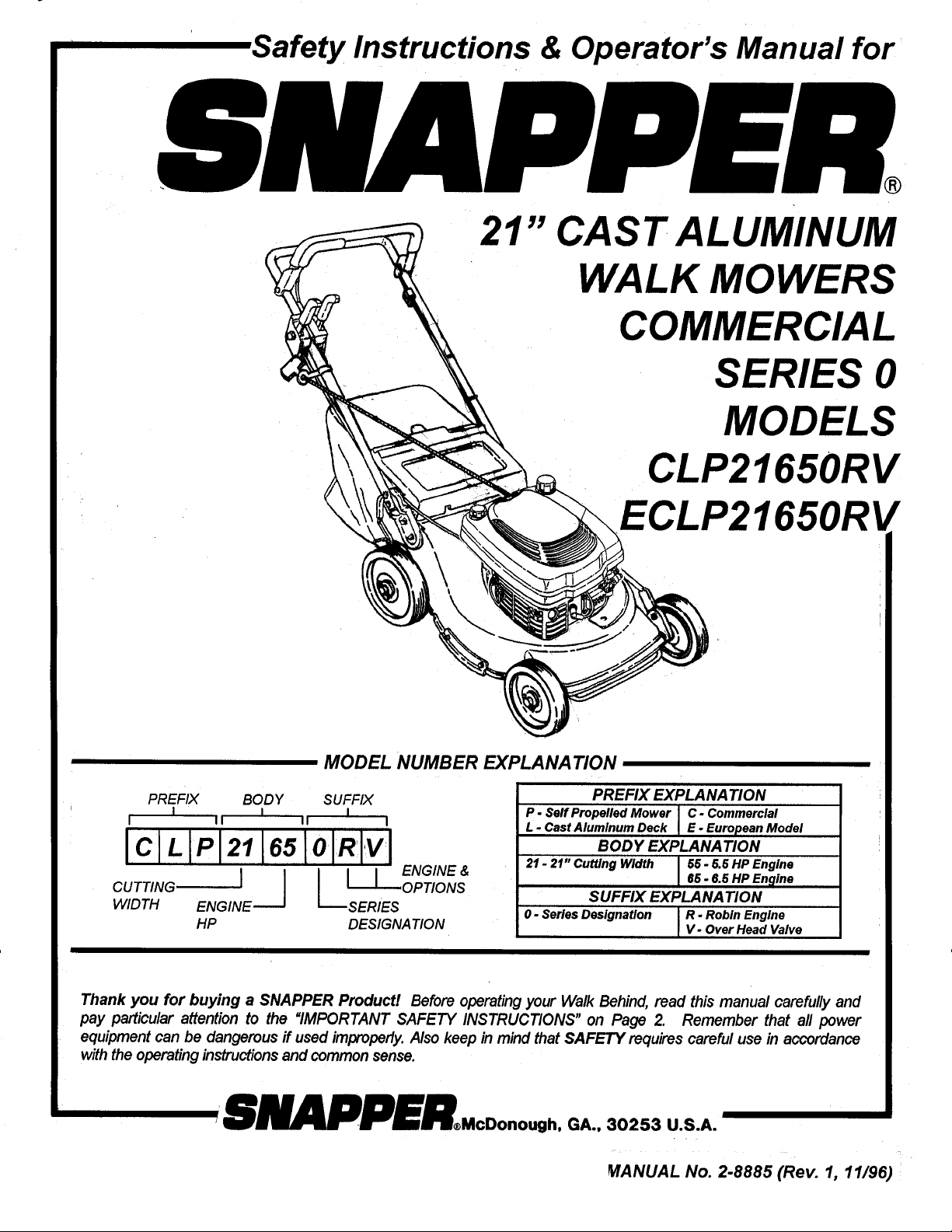
Safety Instructions & Operator's Manual for
21" CAST ALUMINUM
WALK MOWERS
COMMERCIAL
SERIES 0
MODELS
CLP21650RV
MODEL NUMBER EXPLANATION
PREFIX BODY SUFFIX
I I I
I II II I
IclLIPI2 I6sloIR I'v'I
CUTTING I L_OPTION S
WIDTH ENGINE SERIES
lip DESIGNATION
I I I ENGINE &
650RV
PREFIX EXPLANATION
P - Self Propelled Mower I C. Commercial
L. Cast Aluminum Deck I E. European Model
BODY EXPLANATION
21 - 21" Cutting Width I 56 - 6.6 lip Engine
SUFFIX EXPLANATION
0 - Series Designation i R. Robin Engine
166- 6.6lip Engine
V. OverHead Valve
L
Thank you for buying a SNAPPER Product! Before operatingyour Walk Behind, read this manual carefully and
pay particular attention to the "IMPORTANT SAFETY INSTRUCTIONS" on Page 2. Remember that all power
equipment can be dangerous if used improperly.Also keep in mind that SAFETY requires careful use in accordance
withthe operating instructionsand commonsense.
_ANUAL No. 2-8885 (Rev. 1, 11/96)
Page 2

IMPORTANT SAFETY INSTRUCTIONS
WARNING: This powerful machine is capable of amputating hands and feet and can throw objects that can cause
injury and damagel Failure to comply with the following instructions may result in serious injury to the
operator or other persons. The owner of the mower must understand these instructions and, furthermore,
must allow only persons who understand these instructions to operate mower. Each person operating the
mower must be of sound mind and body and must not be under the influence of any substance which might
impair vision, dexterity, or judgment. If you have any questions pertaining to your mower which your dealer
cannot answer to your satisfaction, call or write the Customer Service Department at SNAPPER, McDonough,
Georgia, 30253. Phone: (770) 954-2500.
PROTECTION FOR CHILDREN
t. DO NOT allow children in area when mower is
being operated.
2. DO NOT allow pre-teenage children to operate
mower.
3. Allow only responsible teenagers with mature
judgment or adults to operate mower and only
under close supervision.
4. Keep the area clear of all persons, particularly
small children, and pets.
PREPARATION
1. Never operate mower without proper guards,
plates, safety switches, or other safety
protective devices in place and properly
connected. Inspect to determine that these
safety devices are installed properly, are in good
repair, and operate properly. If the condition or
operation of these devices are questionable,
they must be repaired or replaced before using
the mower. Be thoroughly familiar with the
controls and proper use of the equipment.
2. Thoroughly inspect the area where the mower is
to be used and remove all stones, sticks, wire,
bones and other foreign objects. Also note the
location of holes, stumps, and other possible
hazards.
3. DO NOT operate mower when barefoot or
wearing open sandals. Always wear substantial
footwear and long pants.
4. Fill fuel tank before starting engine. Use
approved fuel container. DO NOT smoke near
open fuel container. DO NOT fill fuel tank
indoors or when engine is running. Allow engine
to cool for at least ten minutes before refilling.
Wipe off any spilled fuel before starting engine.
DO NOT run engine indoors.
5. Make sure that the wheel drive clutch control is
disengaged before starting engine.
6. Never attempt to make a cutting height
adjustment while the engine is running.
7. When mowing over rough ground or in tall
grass, mower must be set at highest cutting
position.
8. Mow only in daylight or in good artificial light.
9. Never operate mower in wet grass. Always be
sure of your footing; keep a firm hold on the
handle and walk; never runl
10. DO NOT operate mower without the grass bag
(and adapter), side chute, mulch cover or
adapter plug in place.
OPERATION
1. DO NOT change engine governor settings or
over speed engine.
2. DO NOT put hands or feet near or under rotating
parts. Keep clear of discharge area while engine
is running.
3. STOP engine when crossing gravel drives,
walks, or roads, and under any conditions where
thrown objects might be a hazard.
4. After striking a foreign object or if mower
vibrates abnormally, STOP the engine,
disconnect and secure spark plug wire. Inspect
the mower for any damage and repair the
damage.
5. STOP blade and engine whenever you leave the
operating position behind the handle for any
reason, including clearing grass, emptying
grass bag and making any adjustments, repairs,
or inspections.
6. Before cleaning, repairing or inspecting, make
certain blade and all moving parts have
STOPPED. Disconnect and secure spark plug
wire away from plug to prevent accidental
starting.
7. STOP engine and wait until the blade comes to
complete STOP before removing grass bag
and/or clearing grass.
8. Mow across slopes, never up-and-down.
Exercise CAUTION when changing directions on
slopes. DO NOT mow steep slopes or other
areas where stability or traction is in doubt.
MAINTENANCE AND STORAGE
1. Keep all nuts, bolts, and screws tight to be sure
mower is in safe operating condition.
2. Never store mower with fuel in tank inside of a
building where fumes may reach an open flame
or spark. Allow engine to cool before storing in
any enclosure.
3. To reduce fire hazard, keep mower free of grass,
leaves, spilled fuel or excessive grease.
4. Check grass bag assembly frequently for wear
or deterioration. Replace with new bag if loose
seams or tears are evident. Replace slider or bag
adapter if broken or cracked.
5. Have your mower inspected and serviced each
year by an authorized Snapper dealer. Determine
if any additional devices are available which
might upgrade the safety of your mower.
6. Factory specified Snapper replacement parts
must be used to assure adequate protection
against injury.
Page 3
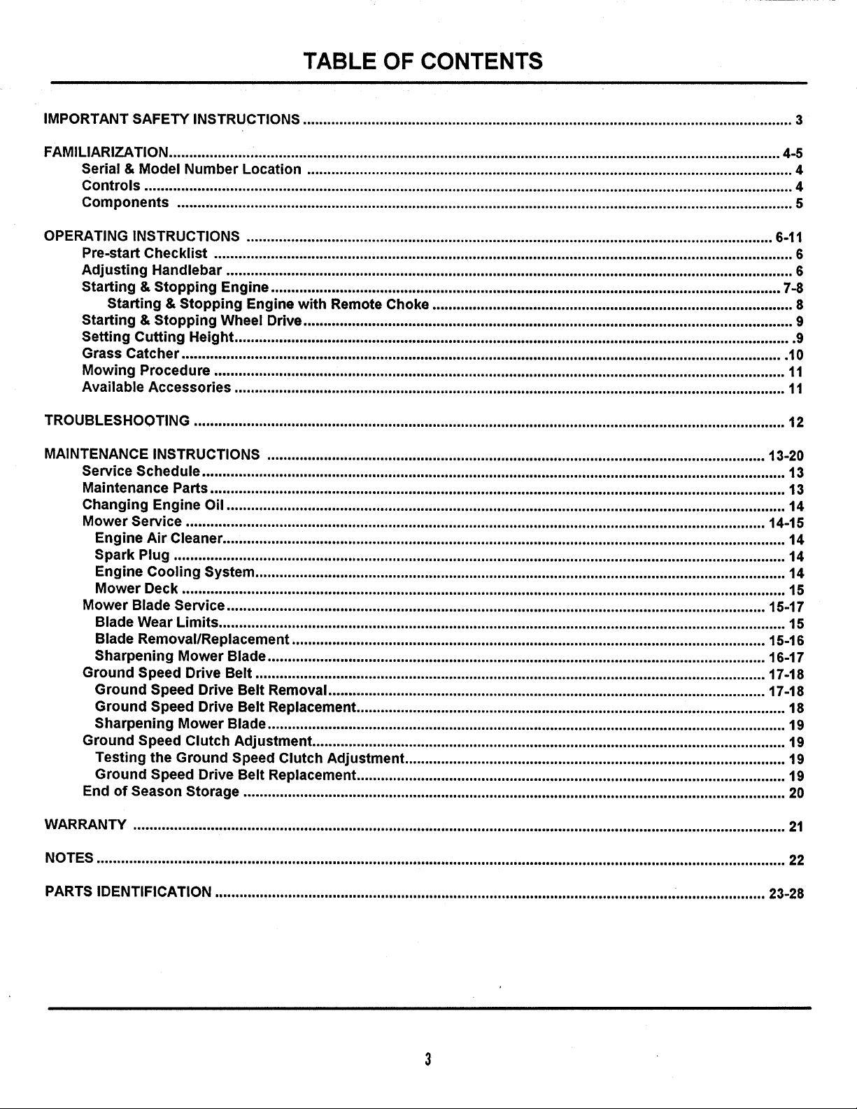
TABLE OF CONTENTS
IMPORTANT SAFETY INSTRUCTIONS ......................................................................................................................... 3
FAMILIARIZATION ....................................................................................................................................................... 4-5
Serial & Model Number Location ........................................................................................................................ 4
Controls ................................................................................................................................................................ 4
Components ........................................................................................................................................................ 5
OPERATING INSTRUCTIONS .................................................................................................................................. 6-11
Pre-start Checklist ............................................................................................................................................... 6
Adjusting Handlebar ............................................................................................................................................ 6
Starting & Stopping Engine .............................................................................................................................. 7-8
Starting & Stopping Engine with Remote Choke ......................................................................................... 8
Starting & Stopping Wheel Drive ......................................................................................................................... 9
Setting Cutting Height .......................................................................................................................................... 9
Grass Catcher ..................................................................................................................................................... 10
Mowing Procedure ............................................................................................................................................. 11
Available Accessories ........................................................................................................................................ 11
TROUBLESHOOTING .................................................................................................................................................. 12
MAINTENANCE INSTRUCTIONS ........................................................................................................................... 13-20
Service Schedule ................................................................................................................................................ 13
Maintenance Parts .............................................................................................................................................. 13
Changing Engine Oil .......................................................................................................................................... 14
Mower Service ............................................................................................................................................... 14-15
Engine Air Cleaner ........................................................................................................................................... 14
Spark Plug ....................................................................................................................................................... 14
Engine Cooling System ................................................................................................................................... 14
Mower Deck ..................................................................................................................................................... 15
Mower Blade Service ..................................................................................................................................... 15-17
Blade Wear Limits ............................................................................................................................................ 15
Blade Removal/Replacement ..................................................................................................................... 15-16
Sharpening Mower Blade ........................................................................................................................... 16-17
Ground Speed Drive Belt .............................................................................................................................. 17-t8
Ground Speed Drive Belt Removal ............................................................................................................ 17-t8
Ground Speed Drive Belt Replacement .......................................................................................................... 18
Sharpening Mower Blade ................................................................................................................................ 19
Ground Speed Clutch Adjustment ..................................................................................................................... t9
Testing the Ground Speed Clutch Adjustment .............................................................................................. 19
Ground Speed Drive Belt Replacement .......................................................................................................... 19
End of Season Storage ...................................................................................................................................... 20
WARRANTY ................................................................................................................................................................. 21
NOTES .......................................................................................................................................................................... 22
PARTS IDENTIFICATION ................................................................................................................. ....................... 23-28
Page 4
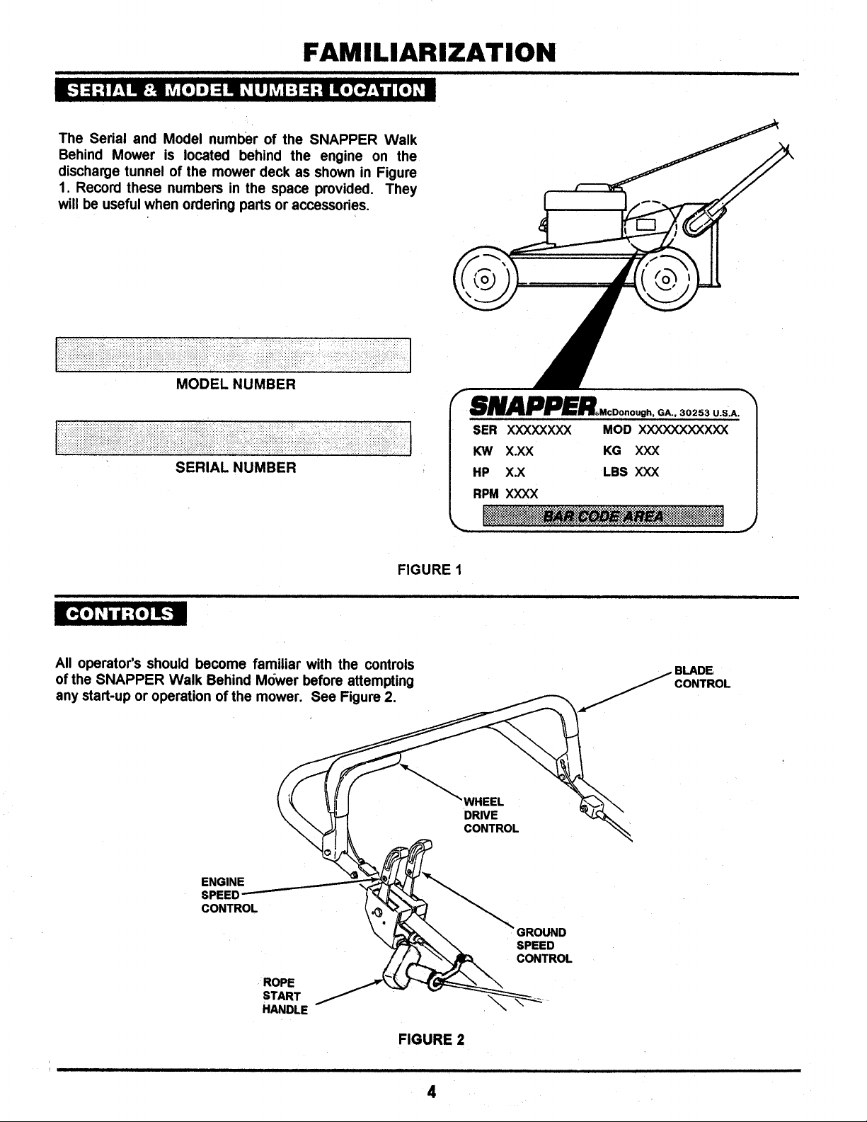
FAMILIARIZATION
The Serial and Model number of the SNAPPER Walk
Behind Mower is located behind the engine on the
discharge tunnel of the mower deck as shown in Figure
1. Record these numbers in the space provided. They
will be useful when ordering parts or accessories.
MODEL NUMBER
SERIAL NUMBER
FIGURE 1
All operator's should become familiar with the controls
of the SNAPPER Walk Behind Mower before attempting
any start-up or operation of the mower. See Figure 2.
_WHEEL
CONTROL
DRIVE
CONTROL
i i i i i
ENGINE
SPEED
CONTROL
GROUND
SPEED
CONTROL
ROPE
START
HANDLE
FIGURE 2
4
Page 5
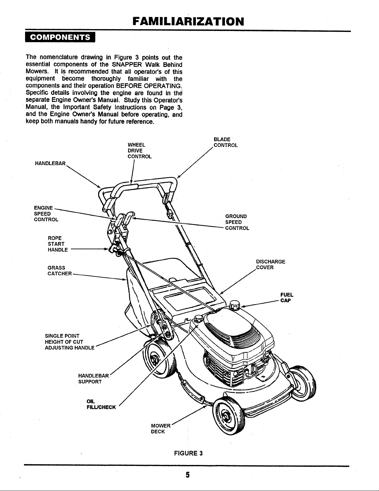
FAMiLiARiZATiON
i i nl I ii ii i
The nomenclature drawing in Figure 3 points out the
essential components of the SNAPPER Walk Behind
Mowers. It is recommended that all operator's of this
equipment I_ecome thoroughly familiar with the
components and their operation BEFORE OPERATING.
Specific details involving the engine are found in the_
separate Engine Owner's Manual. Study this Operator's
Manual, the Important Safety Instructions on Page 3,
and the Engine Owner's Manual before operating, and
keep both manuals handy for future reference.
HANDLEBAR
ENq
SPEED
CONTROL
ROPE
START
HANDLE
GRASS
WHEEL
BLADE
DRIVE
CONTROL
/._CONTROL
GROUND
ISPEED
CONTROL
DISCHARGE
COVER
FUEL
_CAP
SINGLE POINT
HEIGHT OF CUT
ADJUSTING HANDLE
HANDLEBAR
SUPPORT
OIL
FILL/CHECK
MOWER
DECK
FIGURE 3
i i i J i i i ii ii
5
Page 6
OPERATING INSTRUCTIONS
ii i i i i i ii i i iii
Make the following checks and perform service as re-
quired before each start-up.
Check guards; deflectors and covers to make sure they
are all in place and securely tightened. If guards are
missing or damaged, replace before operating mower.
Check engine oil. Add oil as needed to bring up to, but
not over, the FULL mark. Refer to the Engine Owner's
Manual for oil specifications.
Check handlebar adjustment. Adjust as necessary.
Clean exterior surfaces of cutting deck and engine from
any accumulation of grass clippings and debris. Keep
engine air intake screens and cooling fins clean at all
times.
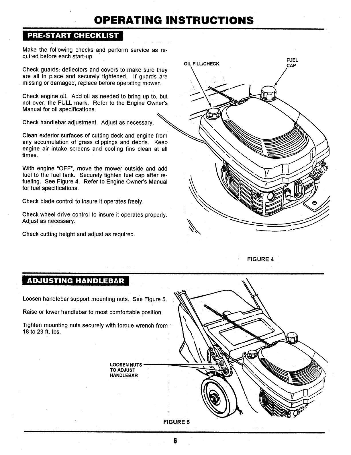
With engine "OFF", move the mower outside and add
fuel to the fuel tank. Securely tighten fuel cap after re-
fueling. See Figure 4. Refer to Engine Owner's Manual
for fuel specifications.
OIL FILL/CHECK
FUEL
CAP
/
Check blade control to insure it operates freely.
Check wheel drive control to insure it operates properly.
Adjust as necessary.
Check cutting height and adjust as required.
Loosen handlebar support mounting nuts. See Figure 5.
Raise or lower handlebar to most comfortable position.
Tighten mounting nuts securely with torque wrench from
18 to 23 ft. Ibs.
LOOSEN NUTS
TO ADJUST
HANDLEBAR
FIGURE 4
FIGURE 5
8
Page 7
OPERATING INSTRUCTIONS
i ii ii i i i i
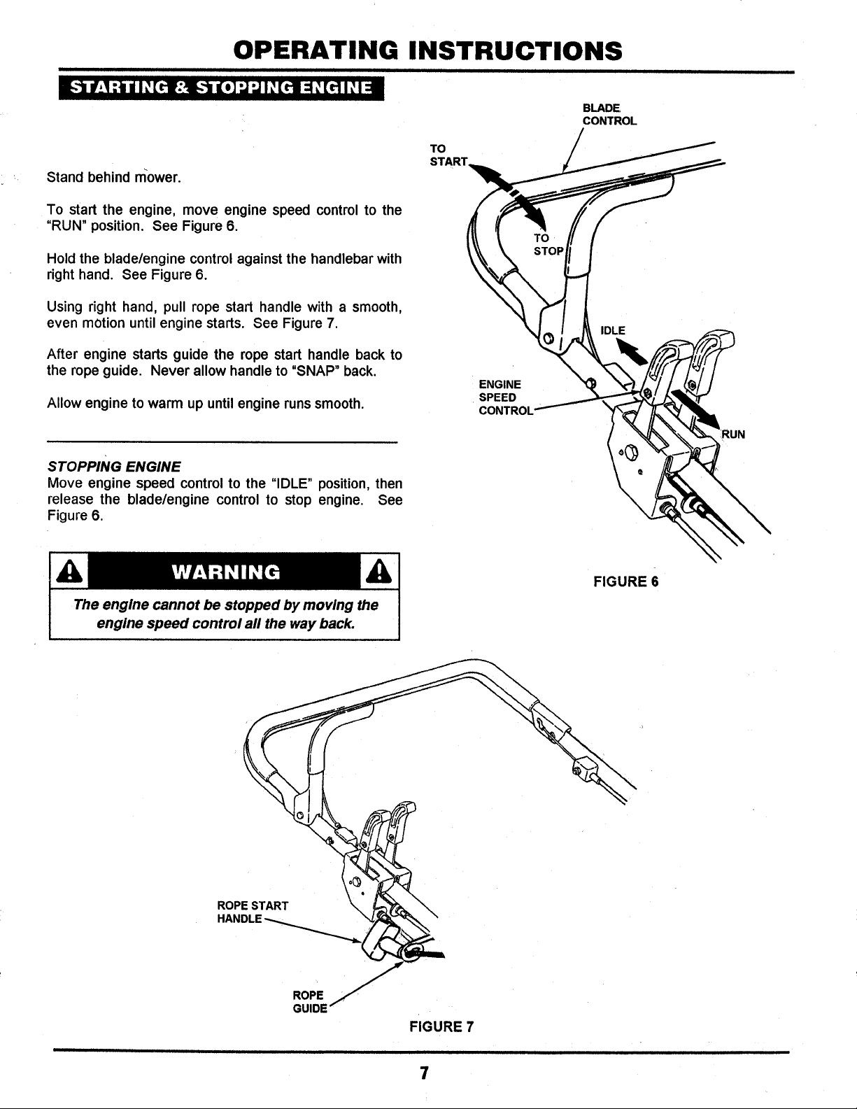
Stand behind mower.
To start the engine, move engine speed control to the
"RUN" position. See Figure 6.
Hold the blade/engine control against the handlebar with
right hand. See Figure 6.
Using right hand, pull rope start handle with a smooth,
even motion until engine starts. See Figure 7.
After engine starts guide the rope start handle back to
the rope guide. Never allow handle to "SNAP" back.
Allow engine to warm up until engine runs smooth.
BLADE
CONTROL
TO
START
ENGINE
SPEED
CONTROL'
RUN
STOPPING ENGINE
Move engine speed control to the "IDLE" position, then
release the blade/engine control to stop engine. See
Figure 6.
The engine cannot be stopped by moving the
engine speed control all the way back.
FIGURE 6
ROPE START
GUIDE
FIGURE 7
7
Page 8

OPERATING INSTRUCTIONS
i i ii i i
STARTING ENGINE WITH REMOTE CHOKE
Push the mower outside.
Move the engine speed controlto the "CHOKE" position.
See Figure 8.
TO
START,
IDLE
BLADE"
CONTROL
ENGINE
SPEE
CONTROL
NOTE:
It may not be necessary to choke the engine when start-
ing a warm engine.
Stand behind mower!
Using left hand, hold the blade/engine control against
the handlebar.
Using right hand, pull rope start handle with a smooth,
even motion until engine starts. See Figure 8.
After engine starts, guide the rope start handle back to
the rope guide. Never allow handle to "SNAP" back.
Move the engine speed control to the "RUN" position
and allow engine to warm up until engine runssmooth.
STOPPING ENGINE
Move engine speed control to the "IDLE" position. See
Figure 9.
Release the bladelengine control to stop engine. See
Figure 9.
CHOKE
TO
STO_ BLADE/
-_J__ CONTROL
ENGINE
SPEED
CONTROL
FIGURE 9
8
Page 9

OPERATING INSTRUCTIONS
ii i i r iiii i
STARTING WHEEL DRIVE
Start engine.
Move ground speed control lever to desired forward
speed. See Figure 10.
TO
i
BLADE
CONTROL
STOP
Pull wheel drive control to handle bar and hold. See
Figure 10.
I!!!i!i!iiii!iiii!iil ll!iiiii!ii!iiii!ii]
DO NOT attempt to change forward speed while the
mower is inmotion. Release the wheel drive control,
then move the ground speed control to the desired
speed.
STOPPING WHEEL DRIVE
Release the wheel drive control. See Figure 10.
Stop engine by releasing blade/engine control. See Fig-
ure 10.
Remove spark plug wire from spark plug and secure
wire away from plug.
Move to right rear tire and pull adjusting handle out until
adjusting handle tab is just clear of the slotted plate.
See Figure 11.
WHEEL
DRIVE
CONTROL
1SPEED
SPEED
3SPEED
GROUND
SPEED
CONTROL
FIGURE 10
ADJUSTING
HANDLE
HIGH
CUT
LOW
CUT
IMPORTANT: DO NOT flex the adjusting handle
outward beyond what is required to change cutting
height. Pulling out to far may cause damage to the
handle.
Move the adjusting handle towards front of mower for
higher cut or toward rear for lower cut. See Figure 11.
The SNAPPER Walk Behind Mower has six cutting
positions ranging from 1" to 4". See Figure 12.
Reinstall spark plug wire onto spark plug and start the
engine to resume mowing.
illll i iii i i _ i
FIGURE 11
4_
3-7/16"
2-718"
2-1/4"
1-518"
1"
FIGURE 12
9
Page 10

OPERATING INSTRUCTIONS
GRASS CATCHER REMOVAL
Move engine speed control to "IDLE".
Stop engine by,releasing blade/engine control.
Remove spark plug wire from spark plug and secure
wire away from plug.
Lift discharge cover.
Grasp grass catcher handle and lift to clear tabs and pull
clear of mower. See Figure 13.
Lower discharge cover.
Dispose of grass clippings properly.
Reinstall grass catcher in reverse order of removal. See
Figure 13.
Reinstall spark plug wire onto spark plug and start
engine.
LIFT DISCHARGE
COVER
FIT ROD ENDS _ _/
OVER TABS"--"_ ( _ TABS
CATCHER
HANDLE
GRASSf_
CATCHER
Never attempt to operate mower without
grass catcher, side discharge chute or
mulching plug properly in place.
FIGURE 13
10
Page 11

OPERATING INSTRUCTIONS
For best results, use the following tips when mowing.
When mowing, cut only 1/3 of grass height. Cutting grass
shorter could be harmful to your lawn.
Ifcutting extremely tall grass, make one cutting with the
deck in its highest cutting position, then lower deck to
desired position and cut a second time.
Mow when lawn is dry.
Mow often. Shorter grass clippings decompose quicker.
Keep mower blades sharp. A dull blade tears and
shreds grass instead of cutting. Your SNAPPER
dealer/retailer can sharpen blades as required.
Alternate mowing pattern to reduce the possibility of
grass matting.
i
Mow with engine speed control in the "RUN" position
and the ground speed lever in a slow forward speed.
Clean deck, removing all grass clippings and debris
from the top and underside of deck after each use.
Below is a list of popular accessories for the SNAPPER Walk Behind Mowers. Contact an authorized SNAPPER dealer
under Lawnmowers in the yellow pages to obtain any of these accessories.
i
MOWER MODEL
CLP21650RV
ECLP21650RV
SIDE DISCHARGE CHUTE KIT MULCHING KIT
6-1397 6-1398
6-1397 6-1398
L i i iii f i iii i i i
11
Page 12

I I i i i i i
TROUBLESHOOTING
i i i j ii r i i i i ii i
ENGINE
WILL NOT
START
ENGINE STALLS
AFTER OR ENGINE
LOSES POWER
i
ENGINE BACKFIRES
WHEN ENGINE
IS STOPPED
EXCESSIVE
VIBRATION
i
CUTTING GRASS
IMPROPERLY
POOR GRASS
DISCHARGE
MOWER LOSES
GROUND SPEED
1•Blade/enginecontrolinreleasedposition• 1.Moveblade/enginecontroltohandlebar.
2• Fuel tank empty• 2. Fillfuel tankwithfresh fuel•
3. Engine needsprimingorchoking•
4. Spark plugwiredisconnected
t. Blade/enginecontrol released•
3. Prime/Chokeengine,
4.Place sparkplugwireontosparkplug•
1.Pullblade/enginecontrolto handlebar
and restartengine.
2. Fuel tankempty.
3. Engine air cleanerdirty.
4. Spark plugdefectiveorgapsatimproperly.
5.
Water. debris or stalefuel in fuel system. 5.
6.
Excessiveload onengine. 6.
7•
Engineoillevellow. 7.
8.
Enginecoolingfinsandairscreensexcessivelydirty. 4.
Enginespeedcontrolset in"RUN"position.
2. Refillfuel tankwithfresh fuel.
3. Cleanor replacefilter•
4.Service sparkplug.
Drainand clean fuel system•
Lessenload.
Fillwithengineoil to properlevel.
Cleanfree of all dirtand debris.
i
1.Set engine speedcontrolto"IDLE" and
allowengineto idle.Then.releaseblade/
11
• Damaged orbentmowerblade.
i
2. Loosebladecomponents.
1. Cuttingheighttoolowor high.
2. Enginespeedtoo slow•
3. ForwardspeedtoofasL
1. Enginespeedtoo slow•
2. Forwardspeedtoofast.
3. Grass is wet.
4. Excessivelywornordamagedblade.
5. Build-upofgrassclippingsand debrisunderdeck.
6. Improperbladeinstalledon deck.
7. Bladeinstalledimproperlyon deck.
1. GroundsPeedcontrolreleased.
'21'Groundspeedcontroldrivebeltwornorbroken.
3. Groundspeedcluichrequiresadjustment.
engine control.
1•Service mowerblade•
2.Service blade and tighten looseparts.
1,Adjustcuttingheight.
2. Move enginespeed controlto"RUN".
3. Set forward speedslower•
1.Move enginespeedcontrolto "RUN".
2. Set forward speedslower.
3. Mowwhen grassis dr,/.
4. Servicemowerblade.
5. Cleandeck.
6. InstallproperSNAPPER blade•
7.InstaJlblade properly.
1.Pullgroundspeedcontroltohandlebar.
2.ReplacebelL
3. Adjusttraction dutch.
Pg. 7/8
Pg.6
Pg.718
Engine Man.
Pg.7/8
Pg.6
Engine Man.
Engine Man.
Engine Man.
Pg.6
Engine Man.
Pg,7/8
i
Pg.15-17
Pg.15-17
Pg.9 & 11
Pg.11
Pg.11
Pg.11
Pg.11
Pg.11
Pg.15-17
Pg.15
Pg.13, 15-17
Pg.15-17
Pg.9
Pg.17-18
Pg.19
H
i ii
12
Page 13

iii i i i i i ii i i ii
MAINTENANCE !INSTRUCTIONS
Engine Oil Check Oil Level Pg. 6 X
Initial Oil Change Pg. 14
Periodic Oil Change Pg. 14
Air Cleaner Clean or Replace Pg. 14
::::::.": ...
X
X
X
Spark Plug Replace Engine
Manual
Engine Clean Engine Shroud Engine
Cooling Manual
System Clean Cooling Fins Engine
Manual
3elt Check For Wear And Tension Pg. 17-18
Mower Blades Check For Wear And Damage Pg. 15
Mower Deck Check Debris Accumulation Pg. 15 X
Clean Outside and Underside Pg. 15 X
*Changeoilevery25hourswhenoperatingunderheavyloador hightemperatures.
X
i X**
I X/ft
' X
x l
x I
x I
i
**Cleanmoreoftenunderdustyconditionsorwhenair debris=s
present.Replaceair cleanerparts,ifverydirty.
x
x
x
x
x
x
x
MOWER MODEL
CLP21650RV
ECLP21650RV
BELT
TRACTION DRIVE
2-4750
2-4750
BLADES
GRASS BAGGING BAGGING / MULCHING
2-6427 2-6428
2-6427 2-6428
13
Page 14

MAINTENANCE INSTRUCTIONS
ii i i i ii i i
CHANGING ENGINE OIL & OIL FILTER
Disconnectspark plugwire and Secure end away from plug.
Place a 2-quart minimum container (not included with
mower) beside mower to allow oil to drain into.
Place blocks under the mower's right wheels. Using a
wrench, remove the oil drain. The oil will drain out. See
Figure 14.
Place a protective covering over the deck area beneath
the oil filter. Remove the oil filter by turning counter-
clockwise as shown in Figure 14.
Clean oil filter base thoroughly with a dry, lint-free cloth.
Install new oil filter and oil filter gasket. Contact engine
manufacturer's authorized dealer for newfilter and gasket.
Reinstall oil drain plug. Remove oil fill cap and dipstick
from engine.
Fill engine with oil as specified in Engine Owner's
Manual. Thereafter, change oil and oil filter after each
25 hours of use.
OIL FILTER (Turn
Counter-clockwise
To Remove)
/
The components listed should be serviced on a regular FIGURE 14
basis to insure that they are in top working condition.
Refer to SERVICE SCHEDULE on Page 13 for recom-
mended service intervals.
The components listed should be serviced on a regular
basis to insure that they are in top working condition.
Refer to SERVICE SCHEDULE on Page 13 for recom-
mended service intervals.
ENGINE AIR CLEANER
The engine air cleaner element should be removed and
replaced every 25 operating hours. See Figure 15 and
refer to the engine owner's manual. Contact engine
manufacturer's dealer for correct replacement air clean-
er element.
SPARK PLUG
Remove and replace engine spark plug after 100 oper-
ating hours or each season, which ever comes first.
Refer to Engine Owner's Manual for correct replace-
ment spark plug and gap specifications.
ENGINE
AIR CLEANER
ELEMENT
ENGINE COOLING SYSTEM
The engine cooling system consists of an engine shroud
and engine fins. These shouldbe kept clean and free of
debris as needed or'clean at least every 50 operating
hours.
i i i
14
FIGURE 15
SPARK
PLUG
Page 15

MAINTENANCE INSTRUCTIONS
i ii i ii i i
MOWER DECK
The mower deck should be cleaned after each use as
follows:
Stop engine, remove spark plug wire from spark plug
and secure wire away from plug.
Remove the grass catcher bag.
Stand mower on rear wheels and scrape off all
accumulation of grass clippings and debris from the
underside of the deck.
Using a garden hose, wash the underside of the deck.
Lower mower to ground. Remove drive belt cover and
clean around drive belt and pulley. See Figure 16.
Clean out all debris and wash out with garden hose.
After cleaning is complete, place spark plug wire onto
Spark plug.
IMPORTANT: When washing, do not allow any water to
reach the top of the transmission. This could cause
extensive damage to the internaltransmissioncomponents.
GROUND SPEED
DRIVE BELT
__ RETAINING
SCREW
FIGURE 16
BLADE WEAR LIMITS
The mower blade should be checked frequently for signs
of excessive wear and damage. Figure 17 illustratesthe
wear limits of the mower blade. Service the blade as
often as necessary to insure optimum cutting perfor-
mance. Refer to Service Schedual on Page 13.
BLADE REMOVAL/REPLACEMENT
Move mower to a firm, level surface.
Stop engine.
Remove spark plug wire from spark plug and secure
wire away from plug.
Remove grass catcher.
Stand mower on rear wheels.
'_ _DGE
C - DANGEROUS CONDITIONI _.
DO NOT USE ON MOWER!
FIGURE 17
15
i i i ii
Page 16

MAINTENANCE INSTRUCTIONS
Remove the two blade mounting screws and nyloc lock
nuts. See Figure 18.
Remove blade and inspect for excessive wear and dam-
age. Refer to Figure 17 for blade wear limits.
Never use a blade that shows signs of
excessive wear or damagel Refer to
Figure 17 for blade wear limits,
Install new blade onto blade hub. Refer to the Mainte-
nance Parts chart on Page 13 for the appropriate blade
part number, See Figure 19.
I TILT MOWER UP ON I
I I_S BACK WHEELS! I
\\
Install blade mounting screws and new nyloc lock nuts,
Torque blade mounting screws and nuts from 30 to 37
foot pounds.
Lower front of mower to ground.
Install grass catcher.
Place spark plug wire onto spark plug.
SHARPENING MOWER BLADE
Move mower to a firm, level surface.
Stop engine.
Remove spark plug wire from spark plug and secure
wire away from plug.
Remove grass catcher.
REMOVE MOUNTING
SCREWS AND NYLOC
LOCK NUTS
FIGURE 18
NYLOC LOCK NUT
BLADE HUB
BLADE_
FLANGE
Stand mower on rear wheels.
Remove the two blade mounting screws and nyloc lock
nuts. See Figure 18.
Remove blade and inspect for excessive wear and/or
damage, Refer to Figure 17 for blade wear limits.
BLADE
MOUNTING
SCREW
FIGURE 19
16
Page 17

MAINTENANCE INSTRUCTIONS
i i iii ii i ii i ii i i i
Never use a blade that shows signs of
Figure 17 for blade wear limits.
Sharpen mower blade at 25° angle. Grind bottom of ._
of blade to sharpen. See Figure 20.
Check balance of blade. Grind heavy end of blade to
achieve balance.
NOTE:
Blade balancers are available and should be used
according to the manufacturers instructions.
Install blade onto blade hub. See Figure 21.
FIGURE 20
Install blade with flanges down. See
Figure 21 for proper installation.
Install blade mounting screws and nyloc lock nuts. See
Figure 21.
Torque blade mounting screws and nuts to between 30
and 37 foot pounds.
Lower front of mower to ground.
Install grass catcher.
Place spark plug wire onto spark plug.
NYLOC LOCK NUT
P,N. 7-6979
BLADE HUB
ENGINE)
FLANGE
BLADE
MOUNTING
SCREW
FIGURE 21
= =
Check the ground speed drive belt every 25 operating
hours for signs of excessive wear and/or damage. Re-
place the belt as necessary.
GROUND SPEED DRIVE BELT REMOVAL
Stop Engine by releasing the blade/engine control.
Remove spark plug wire from spark plug and secure
wire away from plug..
i i i i i i i i iii i
17
Page 18

MAINTENANCE INSTRUCTIONS
i i i ii i ii i i i rl I I I ii ii i i i ii
GROUND SPEED _. /
DRIVE BELT...,_ _ / _ RETAINING
Remove the ground speed drive belt cover.
Remove the ground speed drive belt from around
transmission pulley. See Figure 22.
Remove grass catcher. Stand mower on rear wheels.
Remove the blade hub mounting screw from center of
crankshaft. Remove hub and blade assembly. See
Figure 23.
SCREW
Remove crank shaft protector.
Roll old belt off of engine pulley.
GROUND SPEED DRIVE BELT REPLACEMENT
Place new belt, part number 2-4750 onto engine pulley
and route through the deck housing, and then onto the
transmission pulley. See Figure 23.
Reinstall crankshaft protector into position with the bolts,
but DO NOT tighten at this time.
Reinstallblade hub back onto crankshaft See Figure 24.
Reinstall blade hub mounting screw and torque to 33 to
43 foot pounds. See Figure 24.
IMPORTANT: Position crankshaft protector so there is
.010" clearance between protector and crankshaft.
Torque bolts at 4 to 14 ft. Ibs. Protector MUST NOT
touch the crankshaft. Make sure the belt is on the inside
of the protector belt guides.
Secure spark plug wire onto spark plug.
GROUND SPEED
o.,v cov .J
FIGURE 22
I ITS BACK WHEELSTILT MOWER UP ON I
U
MOUNTING SCREW
FIGURE 23
CRANKSHAFT_
' _1 l___,
I
iI II
i i i
> = .010" CLEARANCE
CRANKSHAFT
!PROTECTOR
"_ FIGURE 24
I I I I I I I II I I I I
18
Page 19

MAINTENANCE INSTRUCTIONS
i iii i i i i i i i i iii ¸ i • i i iii i i
Should a loss of ground speed (Self-Propelling) be ex-
perienced and the ground speed drive belt is in good
condition, test and adjust the ground speed clutch as
follows:
TESTING THE GROUND SPEED CLUTCH/CABLE
ADJUSTMENT
During operation, if the mower will not power itself up-
hill, or while on level ground the mower drive seems to
be slipping, then the mower drive belt probably needs
adjusting. Proceed as follows:
Push mower to level area.
Release wheel drive control lever.
Continue to hold the blade control against the handlebar
and allow engine to keep running. See Figure 25.
HOLD BLADE_ _"
CONTROL AGAINST
HANDLEBAR
FIGURE 25
Reach down with right hand and turn drive belt tension
adjusting wheel counterclockwise two (2) complete
turns. See Figure 26.
Press wheel drive control lever against handlebar and
allow mower to propel itself forward.
If forward motion of mower is still unsatisfactory, turn
adjusting wheel another time.
NOTE: If the mower =creeps" when the ground speed
control is released, the ground speed control cable is too
tight and the adjusting wheel should be rotated
clockwise until all =creeping" is eliminated.
DO NOT overstress drive belt! Turn adjusting
wheel only as much as is required for mower
to propel itself forward!
PULL WHEEL DRIVE
CONTROL AGAINST
HANDLEBAR
FIGURE 26
TURN ADJUSTING WHEEL
CLOCKWISE TO RELEAVE
DRIVE BELT TENSION_
TURN ADJUSTING WHEEL
COUNTERCLOCKWISE T¢
INCREASEDRNEBELTTENSION
VIEW SHOWN FROM "]OPERATOR'S POSITION
19
Page 20

MAINTENANCE INSTRUCTIONS
iii i i iii ii i illll ii ii i iii i ii
Prepare the SNAPPER 21" Series 0 Commercial Walk
Behind Mower for end of season storage as follows:
Drain fuel from fuel tank. Start engine and run until
engine runs out of fuel.
Change engine oil. Refer to Mower Service on Page 14.
Clean or change engine air filter. Refer to Engine
Owner's Manual.
Remove grass catcher and empty all contents to
prevent decay and mold. The grass catcher may be
washed in detergent, rinsed thoroughly and allowed to
completely dry to prevent molding.
Remove traction drive belt cover and remove debris
accumulation from around drive belt and transmission
pulley. See Figure 27.
Clean underside of deck and remove all grass and
debris accumulation using a brush and scraper. Refer
to Page 15.
Wash down entire mower and allow to dry.
REMOVE DEBRIS
ACCUMULATION
FROM THIS AREA RETAINING
_ . SCREW
//
TRACTION DRIVE
BELT COVER
FIGURE 27
CAUTION
When washing mower, DO NOT allow any water to
!reach the top of the transmission or the engine. This
icould cause extensive damage to the transmissions
iinternal components and/or the engine.
Reinstall the traction drive belt cover and secure with
retaining screw. See Figure 27.
Loosen curved head bolts and nuts connecting handle-
bar to the handlebar support brackets on each side of
mower. See Figure 28.
Carefully fold handlebar over engine. Move mower to
desired storage site.
NOTE: When folding handlebars, be careful not to let
the cables hang-up or become kinked.
HANDLEBAR
CURVED HEAD
BOLT & NUT
HANDLEBAR
SUPPORT
BRACKET
ii i i i i
FIGURE 28
iiiii
2O
Page 21

8NAPPER
,_ 1 YEAR COMMERCIAL LIMITED WARRANTY _'
_i_ For one (1) year from purchase date for the original purchaser's commercial, rental, or other non-residential use,
_i_ SNAPPER, through any SNAPPER dealer will replace, free of charge (except for taxes where applicable), any
_i_ part or parts found upon examination by the factory at McDonough, Georgia, to be defective in material or
workmanship or both.
All transportation costs incurred by the purchaser in submitting material to a SNAPPER dealer for replacement
under this warranty must be paid by the purchaser.
This warranty does not apply to engines and their components, hydro transmissions, gear drive transmissions
and batteries, as these items are warranted separately. This warranty does not apply to parts that have been
_i_ damaged by accident, alteration, abuse, improper lubrication, normal wear, or other cause beyond our control.
There is no other express warranty.
Implied warranties, including those of merchantability and fitness for a particular purpose, are limited to one (1)
year from purchase date for the original purchaser's commercial, rental or other non-residential use, and to the
extent permitted by law any and all implied warranties are excluded. This is the exclusive remedy, Liabilities for
consequential damages, under any and all warranties are excluded;
Some states do not allow limitations on how long an implied warranty lasts, or do not allow the exclusion or
_i_ limitation of incidental or consequential damages, so the above limitation or exclusion may not apply to you.
_, This warranty gives you specific legal rights, and you may also have other rights which vary from state to state.
_i_ WARNING: THE USE OF REPLACEMENT PARTS OTHER THAN GENUINE SNAPPER PARTS MAY IMPAIR
THE SAFETY OF SNAPPER PRODUCTS AND WILL VOID ANY LIABILITY AND WARRANTY BY
_i_ SNAPPER ASSOCIATED WITH THE USE OF SUCH PARTS.
IMPORTANT: Please fill outthe attachedSNAPPER Product RegistrationCard immediately andmail to:
SNAPPER, McDONOUGH, GEORGIA 30253.
21
Page 22

' N
O
T
I
E
S
T
I I
22
Page 23

Safety Instructions & Operator's Manual for
®
21" CAST ALUMINUM
WALK MOWERS
COMMERCIAL
SERIES 0
MODELS
CLP21650RV
ECLP21650RV
A WARNING: California to cause cancer, birth defects or other reproductive harm.
I _°e°_i_eex_aus_°__i__°_u_c°°_ai_sc_e_ic°'__n°w°_°_e_°°_1
MANUAL No. 2-8885 (Rev. 1, 11/96)
Printed in U.S.A.
 Loading...