

Page 1
Not for
Reproduction
80030025USCN
Revision: A
Page 2
Manual Contents:
Not for
Reproduction
Operator Safety.....................................................................2
indicates a hazardous situation which, if not avoided, could
result in death or serious injury.
Features and Controls..........................................................8
Operation...............................................................................8
Maintenance.........................................................................15
Troubleshooting..................................................................28
Warranties............................................................................29
Slope Guide.........................................................................34
Specifications......................................................................35
The images in this document are representative, and are meant
to complement the instructional copy they accompany. Your
unit may vary from the images displayed.
as seen from the operator's position.
Thank you for purchasing this quality-built Snapper Walkbehind
Mower. We’re pleased that you’ve placed your confidence in
the Snapper brand. When operated and maintained according
to the manuals, your Snapper product will provide many years
of dependable service.
The manuals contain safety information to make you aware of
the hazards and risks associated with the unit and how to avoid
them. This Walkbehind Mower was designed to be used as
described in operator's manual and is not intended for any other
purpose. It is important that you read and understand the
instructions thoroughly before attempting to start or operate this
equipment. Save these original instructions for future reference.
This product requires final assembly before use. Refer to the
setup guide for instructions on final assembly procedures. Follow
the instructions completely.
LEFT
and
RIGHT
are
Operator Safety
Safety Definitions
For your safety, the safety of others, and to protect the
performance of equipment, follow the precautions listed
throughout the manual before operation, during operation, and
during maintenance procedures.
indicates a potential personal injury hazard.
CAUTION
indicates a hazardous situation which, if not avoided, could
result in minor or moderate injury.
NOTICE
indicates a situation which can cause damage to the equipment,
personal property and/or the environment, or cause the
equipment to operate improperly.
Safety Symbol Definitions
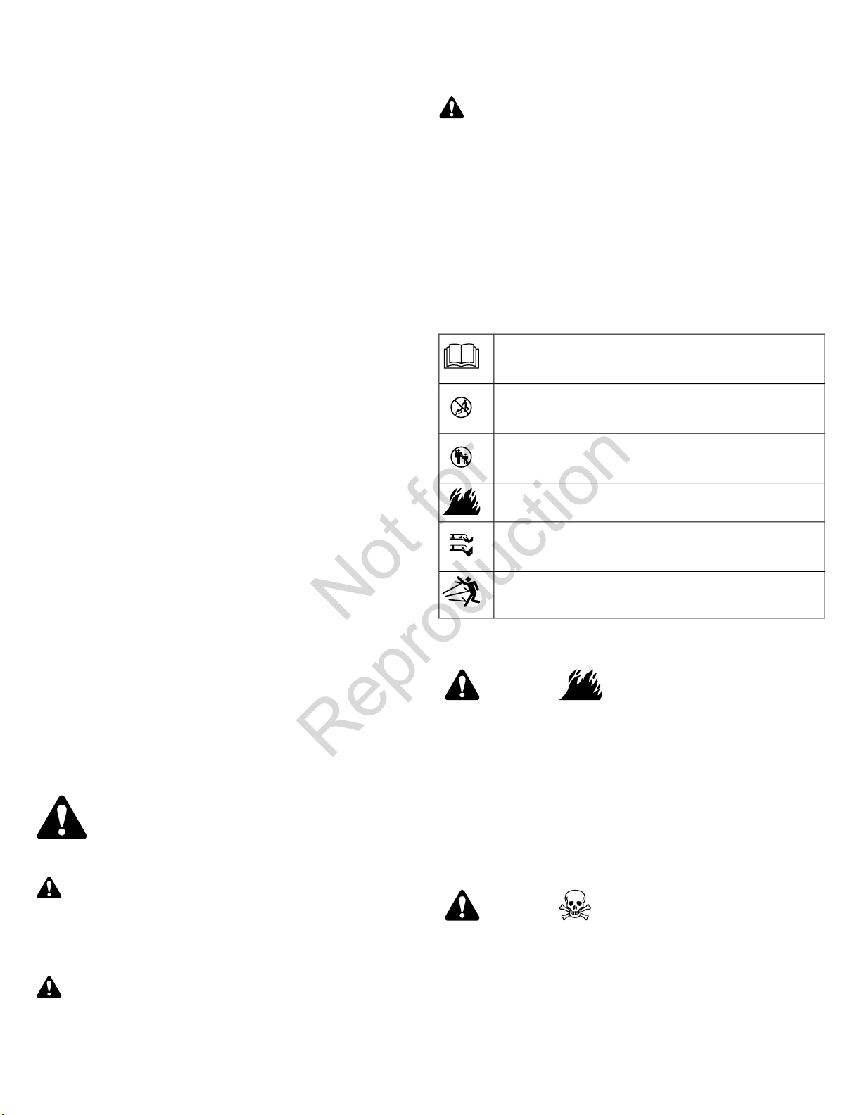
The following safety symbols may be found on the unit.
Read the operator’s manual before attempting to operate the
mower.
Mow across slopes, not up or down.
To avoid injury to others, do not mow when others, especially
children, are around.
To reduce the potential for fire, wait at least 2 minutes before
refueling.
To avoid serious injury or death, keep hands and feet away from
the mower deck at all times during operation.
To avoid injury from thrown objects, do not operate the mower
unless all mulching, discharge, or bagging components are in their
proper place.
California Spark Arrester Warning
WARNING
It is a violation of California Public Resource Code, Section
4442, to use or operate the engine on any forest-covered,
brush-covered, or grass-covered land unless the exhaust
system is equipped with a spark arrester, as defined in Section
4442, maintained in effective working order. Other states or
federal jurisdictions may have similar laws. Contact the original
equipment manufacturer, retailer, or dealer to obtain a spark
arrester designed for the exhaust system installed on this
engine.
DANGER
indicates a hazardous situation which, if not avoided, will result
in death or serious injury.
WARNING
2 www.snapper.com
WARNING
Battery posts, terminals, and related accessories contain
lead and lead compounds, chemicals known to the State
of California to cause cancer and birth defects or other
reproductive harm. Wash hands after handling.
Page 3
California Proposition 65
3.5 ft
(1,5 m)
20.0 ft
(6,0 m)
Not for
Reproduction
This product can expose you to chemicals including gasoline
engine exhaust, which is known to the State of California to
cause cancer, and carbon monoxide, which is known to the
State of California to cause birth defects or other reproductive
harm. For more information go to www.P65Warnings.ca.gov.
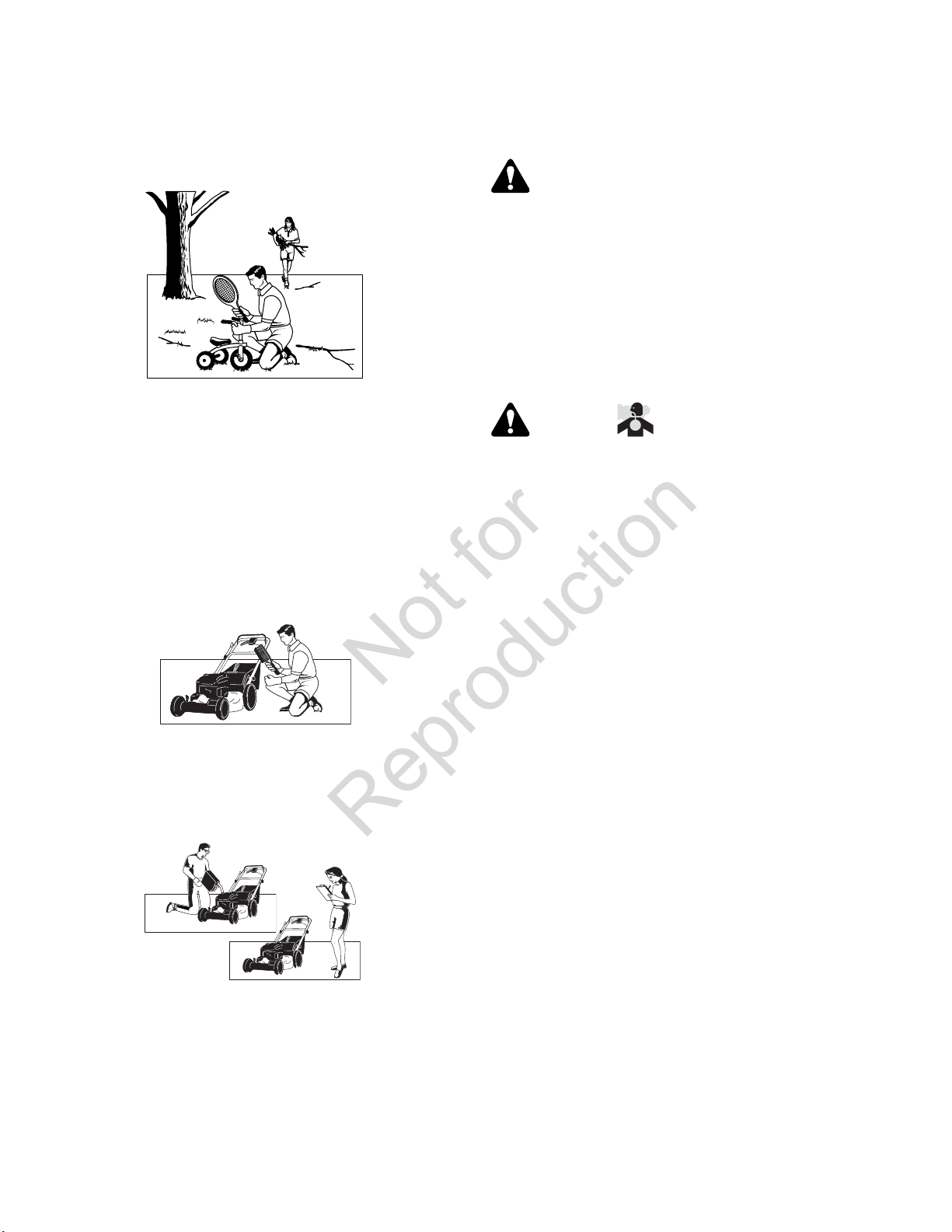
Operating Safety
Tragic accidents can occur with children. Do not allow them
anywhere near the area of operation. Children are often attracted
to the unit and mowing activity. Never assume that children will
remain where you last saw them. If there is a risk that children
may enter the area where you are mowing, have another
responsible adult watch them.
Slope Operation
Power equipment is only as safe as the operator. If it is misused,
or not properly maintained, it can be dangerous! Remember,
you are responsible for your safety and that of those around
you.
Use common sense, and think through what you are doing. If
you are not sure that the task you are about to perform can be
safely done with the equipment you have chosen, ask a
professional: contact your local authorized dealer.
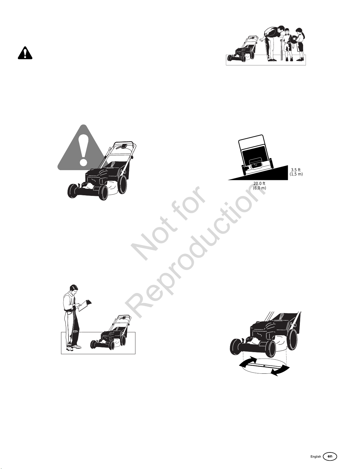
Read the Manual
The operator’s manual contains important safety information
you need to be aware of BEFORE you operate your unit as well
as DURING operation.
Safe operating techniques, an explanation of the product’s
features and controls, and maintenance information is included
to help you get the most out of your equipment investment.
Be sure to completely read the Safety Rules and Information
found on the following pages. Also completely read the
Operation section.
You could be seriously injured or even killed if you use this unit
on too steep an incline. Using the unit on a slope that is too
steep or where you don’t have adequate footing or traction can
cause you to lose control or slip and fall.
You should not operate on inclines with a slope greater than 10
degrees, which is a 3.5 ft (1,5 m) rise over 20.0 ft (6,0 m).
Always mow across slopes, never up and down.
Also note that the surface you are mowing can greatly impact
control. Wet grass or leaves can seriously affect your footing
and traction on a slope.
If you feel about operating the unit on an incline, don’t do it. It’s
not worth the risk.
Moving Parts
This equipment has moving parts that can injure you or someone
else. However, if you stand behind the handle properly and
follow all the rules in this book, the unit is safe to operate.
The mower has a spinning mower blade that can amputate
hands and feet. Do not allow anyone near the equipment while
it is running!
Children
3
Page 4
To help you, the operator, use this equipment safely, it is
Not for
Reproduction
equipped with an operator present safety system. Do NOT
attempt to alter or bypass the system. See your dealer
immediately if the system does not pass all the safety interlock
system tests found in this manual.
Thrown Objects
This unit has a spinning mower blade. This blade can pick up
and throw debris that could seriously injure a bystander. Be
sure to clean up the area to be mowed BEFORE you start
mowing.
Do not operate this unit without the entire grass catcher or
discharge guard (deflector) in place.
Also, do not allow anyone in the area while the unit is running!
If someone does enter the area, turn the unit off immediately
until they leave.
Debris Accumulation
Proper maintenance is critical to the safety and performance of
your unit. Be sure to perform the maintenance procedures listed
in this manual, especially periodically testing the safety system.
General Safety Messages
WARNING
This powerful cutting machine is capable of amputating hands
and feet and can throw objects that can cause injury and
damage! Failure to comply with the following SAFETY
instructions could result in serious injury or death to the
operator or other persons. The owner of the machine must
understand these instructions and must allow only persons
who understand these instructions to operate machine. Each
person operating the machine must be of sound mind and
body and must not be under the influence of any substance,
which might impair vision, dexterity or judgment.
WARNING
Poisonous Gas Hazard
Engine exhaust contains carbon monoxide, a poisonous gas
that could kill you in minutes. You CANNOT see it, smell it,
or taste it. Even if you do not smell exhaust fumes, you could
still be exposed to carbon monoxide gas. If you start to feel
sick, dizzy, or weak while using this product, shut it off and
get to fresh air RIGHT AWAY. See a doctor. You may have
carbon monoxide poisoning.
Accumulation of grass and debris can result in a fire. Be sure
to clean any accumulation of grass and debris with a brush or
compressed air, before and after operation.
Fuel and Maintenance
Gasoline is extremely flammable. Its vapors are also extremely
flammable and can travel to distant ignition sources. Gasoline
must only be used as a fuel, not as a solvent or cleaner. It should
never be stored any place where its vapors can build up or travel
to an ignition source like a pilot light. Fuel belongs in an
approved, plastic, sealed gas can, or in the tractor fuel tank with
the cap securely closed. Spilled fuel needs to be cleaned up
immediately.
• Operate this product ONLY outside far away from
windows, doors and vents to reduce the risk of carbon
monoxide gas from accumulating and potentially being
drawn towards occupied spaces.
• Install battery-operated carbon monoxide alarms or plug-in
carbon monoxide alarms with battery back-up according
to the manufacturer’s instructions. Smoke alarms cannot
detect carbon monoxide gas.
• DO NOT run this product inside homes, garages,
basements, crawlspaces, sheds, or other
partially-enclosed spaces even if using fans or opening
doors and windows for ventilation. Carbon monoxide can
quickly build up in these spaces and can linger for hours,
even after this product has shut off.
• ALWAYS place this product downwind and point the
engine exhaust away from occupied spaces.
Protection For Children
Tragic accidents can occur if the operator is not alert to the
presence of children. Children are often attracted to the machine
and the mowing activity. Never assume that children will remain
where you last saw them.
1. KEEP children out of the mowing area and under the
watchful care of a responsible adult other than the operator.
2. DO NOT allow children in yard when machine is operated
and turn machine OFF if anyone enters the area.
3. DO NOT allow pre-teenage children to operate machine.
4 www.snapper.com
Page 5

4. ALLOW only responsible adults & teenagers with mature
Not for
Reproduction
judgment under close adult supervision to operate machine.
5. DO NOT pull mower backwards unless absolutely
necessary. LOOK and SEE behind and down for children,
pets and hazards before and while backing.
6. USE EXTRA CARE when approaching blind corners,
shrubs, trees, or other objects that may obscure vision.
Slope Operation
1. Slopes are a major factor related to slip and fall accidents,
which can result in severe injury. All slopes require extra
caution. If you feel uneasy on a slope, DO NOT mow it.
2. Mow across slopes, never up-and-down. Exercise extreme
CAUTION when changing directions on slopes. DO NOT
mow steep slopes or other areas where stability or traction
is in doubt. Refer to the Slope Guide at the back of this
manual.
3. Use extra care with grass catchers or other attachments;
these affect the handling and the stability of the machine.
Preparation
1. Read, understand, and follow instructions and warnings in
this manual and on the mower, engine and attachments.
Know the controls and the proper use of the mower before
starting.
2. Only mature, responsible persons shall operate the machine
and only after proper instruction.
3. Data indicates that operators age 60 and above, are
involved in a large percentage of mower-related injuries.
These operators should evaluate their ability to operate the
mower safely enough to protect themselves and others from
serious injury.
4. Handle fuel with extra care. Fuels are flammable and vapors
are explosive. Use only an approved fuel container. DO
NOT remove fuel cap or add fuel with engine running. Add
fuel outdoors only with engine stopped and cool. Clean
spilled fuel and oil from machine. DO NOT smoke.
5. Check the area to be mowed and remove all objects such
as toys, wire, rocks, limbs and other objects that could cause
injury if thrown by blade or interfere with mowing. Also note
the location of holes, stumps, and other possible hazards.
6. Keep people and pets out of the mowing area. Immediately,
STOP Blade, Stop engine and Stop mower if anyone enters
the area.
7. Check shields, deflectors, switches, blade controls and
other safety devices frequently for proper operation and
location.
8. Make sure all safety decals are clearly legible. Replace if
damaged.
9. Protect yourself when mowing and wear safety glasses,
long pants and substantial footwear. DO NOT mow
barefooted or with sandals.
10. Know how to STOP blade and engine quickly in preparation
for emergencies.
11. Use extra care when loading or unloading the machine into
a trailer or truck.
12. Check grass catcher components frequently for signs of
wear or deterioration and replace as needed to prevent
injury from thrown objects going through weak or torn spots.
Safe Handling Of Gasoline
To avoid personal injury or property damage, use extreme care
in handling gasoline. Gasoline is extremely flammable and the
vapors are explosive.
1. Extinguish all cigarettes, cigars, pipes and other sources
of ignition.
2. Use only an approved fuel container.
3. DO NOT remove fuel cap or add fuel with the engine
running. Allow the engine to cool before refueling.
4. DO NOT refuel the machine indoors.
5. DO NOT store the machine or fuel container inside where
there is an open flame, spark or pilot light such as on a
water heater or other appliances.
6. DO NOT fill fuel containers inside a vehicle or on a truck or
trailer bed with a plastic liner. Always place the containers
on the ground away from the vehicle before filling.
7. Remove gas-powered equipment from the vehicle or trailer
and refuel it on the ground. If this is not possible, then refuel
equipment using a portable container, rather than a gasoline
dispenser nozzle.
8. DO NOT start gas powered equipment in enclosed vehicles
or trailers.
9. Keep the nozzle in contact with the rim of the fuel tank or
container opening at all times until fueling is complete. DO
NOT use a nozzle lock-open device.
10. If fuel is spilled on clothing, change clothing immediately.
11. DO NOT overfill a fuel tank. Replace fuel cap and tighten
securely.
Operation
1. DO NOT put hands or feet near or under rotating parts.
Keep clear of discharge area while engine is running.
2. STOP engine when crossing gravel drives, walks, or roads,
and under any conditions where thrown objects might be a
hazard.
3. Mow only in daylight or good artificial light.
4. DO NOT operate mower while under the influence of alcohol
or drugs.
5. After striking a foreign object or if mower vibrates
abnormally, STOP the engine, disconnect and secure spark
plug wire. Inspect the mower for any damage and repair
the damage before starting.
6. DO NOT mow near drop offs, ditches or embankments.
Operator could lose footing or balance.
7. STAY ALERT for holes and other hidden hazards. Tall grass
can hide obstacles. Keep away from ditches, washouts,
culverts, fences and protruding objects.
5
Page 6

8. DO NOT mow on wet grass. Always be sure of your footing.
Not for
Reproduction
Keep a firm hold on the handle and walk, never run. Slipping
could cause injury.
9. ALWAYS stay behind handle when engine (motor) is
running.
10. DO NOT leave the machine with the engine running. STOP
BLADE and STOP ENGINE before leaving the operators
position for any reason.
11. Before cleaning, repairing or inspecting make certain engine,
blade and all moving parts have STOPPED. Disconnect
and secure spark plug wire away from plug to prevent
accidental starting.
12. STOP engine and wait until the blade comes to complete
STOP before removing grass bag and/or clearing grass.
13. DO NOT operate mower without the entire grass catcher,
rear guard, or other safety devices in place and working.
DO NOT point discharge at people, passing cars, windows
or doors.
14. DO NOT discharge material against a wall or obstruction.
Material may ricochet back towards the operator.
15. Slow down before turning.
16. Watch out for traffic when near or crossing roadways.
17. DO NOT operate engine in enclosed areas. Engine exhaust
gases contain carbon monoxide, a deadly poison.
18. Only use accessories approved by the manufacturer. See
manufacturer’s instructions for proper operation and
installation of accessories.
Maintenance And Storage
moving parts. Replace with new bag if loose seams or tears
are evident. Replace slider or bag adapter if broken or
cracked.
9. Mower blades are sharp and can cut. Wrap the blades or
wear heavy leather gloves and use CAUTION when
handling them.
10. DO NOT test for spark by grounding spark plug next to
spark plug hole; spark plug could ignite gas exiting engine.
11. Have machine serviced by an authorized dealer at least
once a year and have the dealer install any new safety
devices.
12. Use only factory authorized replacement parts or like parts
when making repairs.
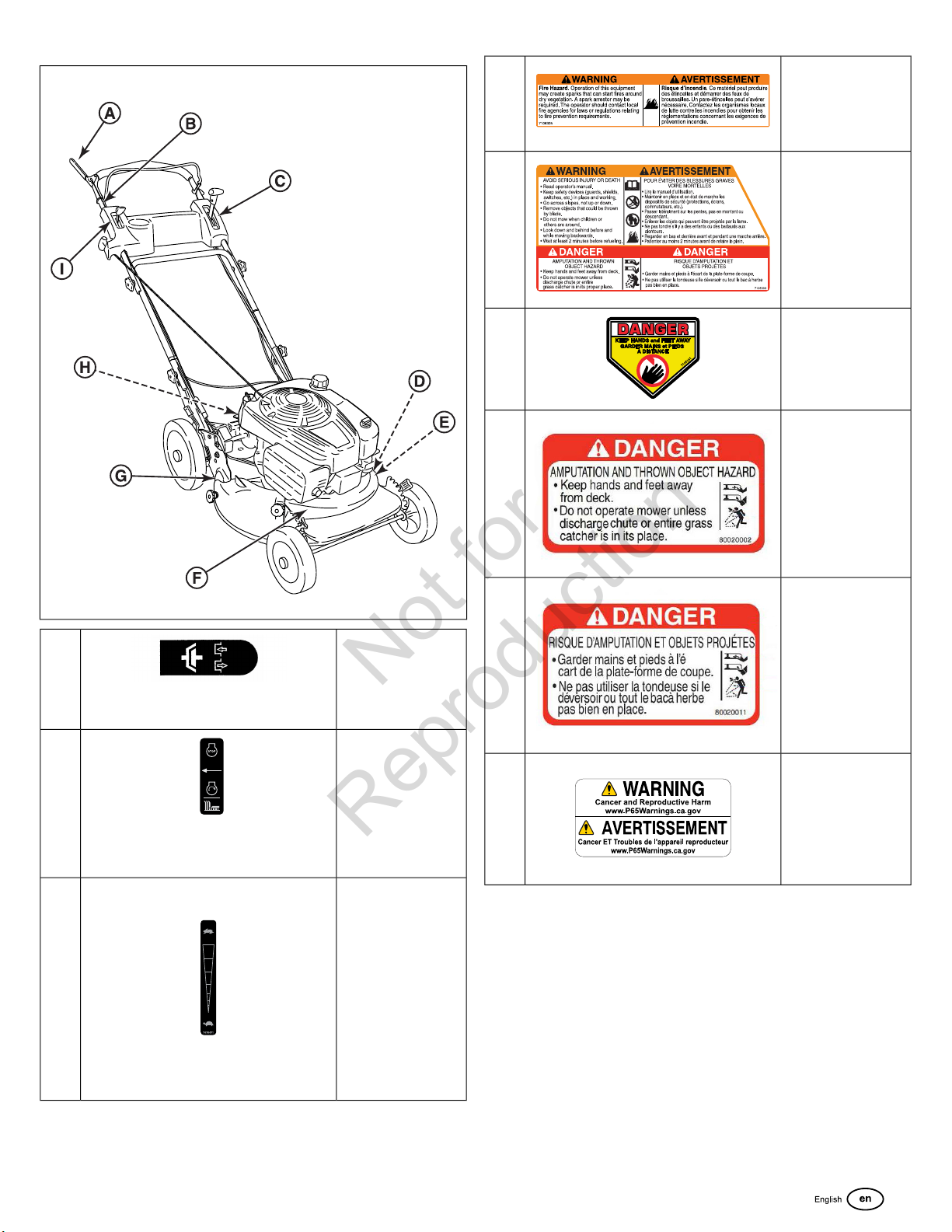
Safety and Operation Decals
Reading this manual and the safety instructions it contains will
provide the basic knowledge necessary to operate this mower
safely and effectively. However, several safety and operation
decals have also been placed on the mower as a reminder of
this important information during operation.
The decals noted below are located on the mower. The safety
warnings and operation instructions they contain should be
carefully read, understood, and followed. Not following these
important warnings and instructions can result in serious bodily
injury or death.
If any of these decals are lost or damaged, replace them
immediately. Contact your dealer for replacement decals.
Compare Figure 1 with the table following.
1. DO NOT store mower or fuel container inside where fumes
may reach an open flame, spark or pilot light such as in a
water heater, furnace, clothes dryer or other gas appliance.
Allow engine to cool before storing machine in an enclosure.
Store fuel container out of reach of children in a well
ventilated, unoccupied building.
2. Keep mower and engine free of grass, leaves or excess
grease to reduce fire hazard and engine overheating.
3. When draining fuel tank, drain fuel into an approved
container outdoors and away from open flame.
4. Keep all bolts, especially blade bolts, nuts and screws
properly tight. Check that all cotter pins are in proper
position.
5. Always provide adequate ventilation when running engine.
Engine exhaust gases contain carbon monoxide, a deadly
poison.
6. Service engine and make adjustments only when engine
is stopped. Removed spark plug wire from spark plug and
secure wire away from spark plug to prevent accidental
starting.
7. DO NOT change engine governor speed settings or
overspeed engine.
8. Check grass bag assembly frequently for wear or
deterioration to avoid thrown objects and exposure to
6 www.snapper.com
Page 7
1
Not for
Reproduction
D
WARNING: Spark
Arrestor may be
required.
E
F
G
G
A
Drive Control
• Squeeze drive
control against
handle to engage
wheel drive.
WARNING: Avoid
Serious Injury or Death
DANGER: Keep Hands
and Feet Away.
DANGER: Amputation
and Thrown Object
Hazard.
DANGER: Amputation
and Thrown Object
Hazard.
B
C
OPC (Blade Control)
• Squeeze blade
control to start
and run engine
and blade.
• Release blade
control to stop
engine and blade.
Ground Speed Control
• Move ground
speed control
toward Fast
(Rabbit) to
increase ground
speed.
• Move ground
speed control
toward Slow
(Turtle) to
decrease ground
speed.
H
WARNING: Cancer
and Reproductive
Harm.
7
Page 8
I
Not for
Reproduction
Engine Speed Control
• Move engine
speed control
lever toward Slow
(Turtle) to
decrease engine
speed.
• Move engine
speed control
lever toward Fast
(Rabbit) to
increase engine
speed.
• Move engine
speed control
lever past Fast
(Rabbit) to turn
on choke.
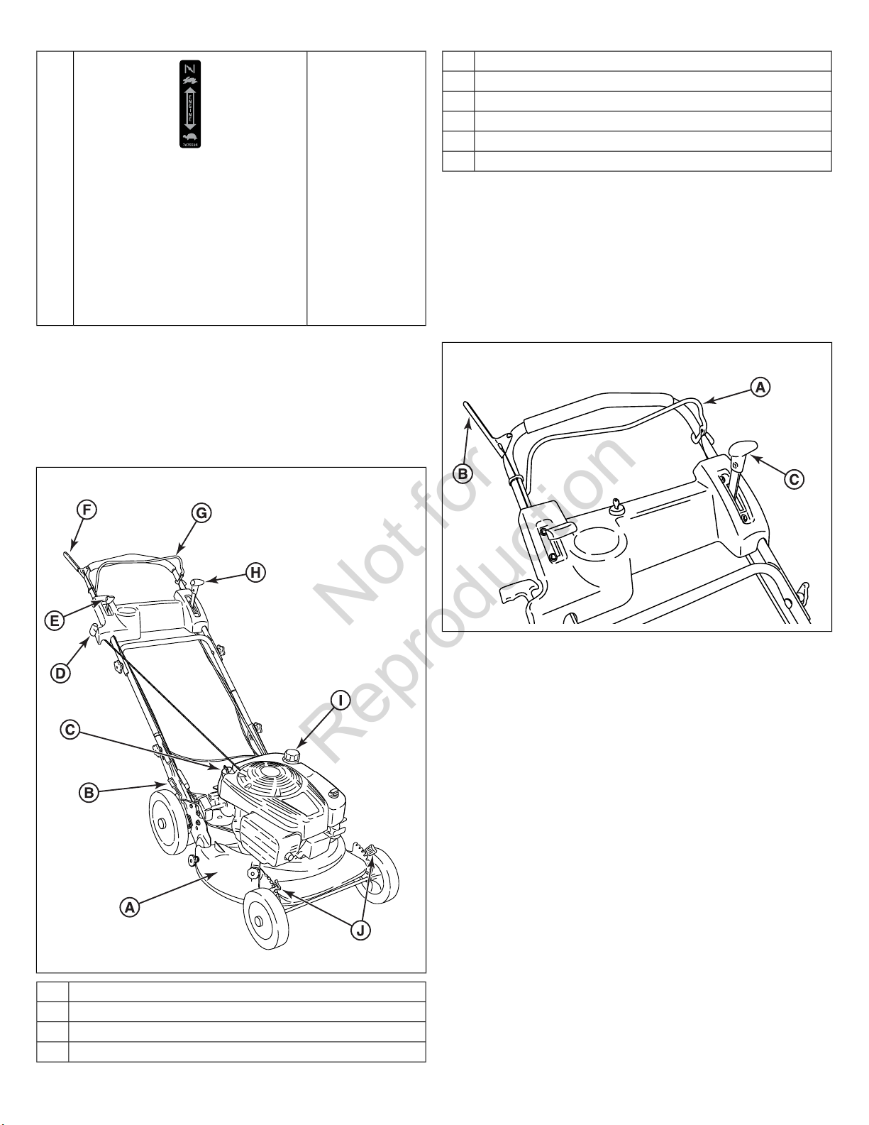
Engine Speed ControlE
Drive ControlF
Blade ControlG
Ground Speed ControlH
Fuel Filler CapI
Front Height Adjustment Latch (2)J
Operation
Before Starting
1. Check the guards, deflectors, grass bag, and covers to
make sure all are in place and securely tightened.
2. Check the blade control (A, Figure 3), drive control (B), and
ground speed control (C) to insure they work freely.
Features and Controls
Note:
The figures and illustrations in this manual are provided
for reference only and may differ from your specific model.
Contact your dealer if you have questions.
Compare Figure 2 with the table following.
2
3
3. Check the cutting height. Adjust to the desired height. See
Cutting Height Adjustment
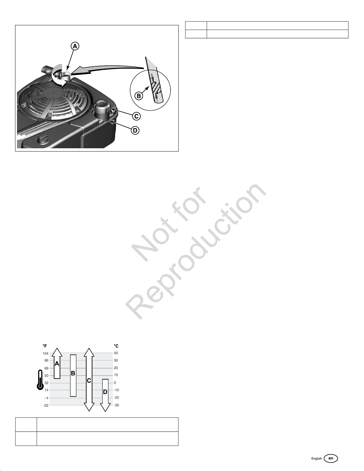
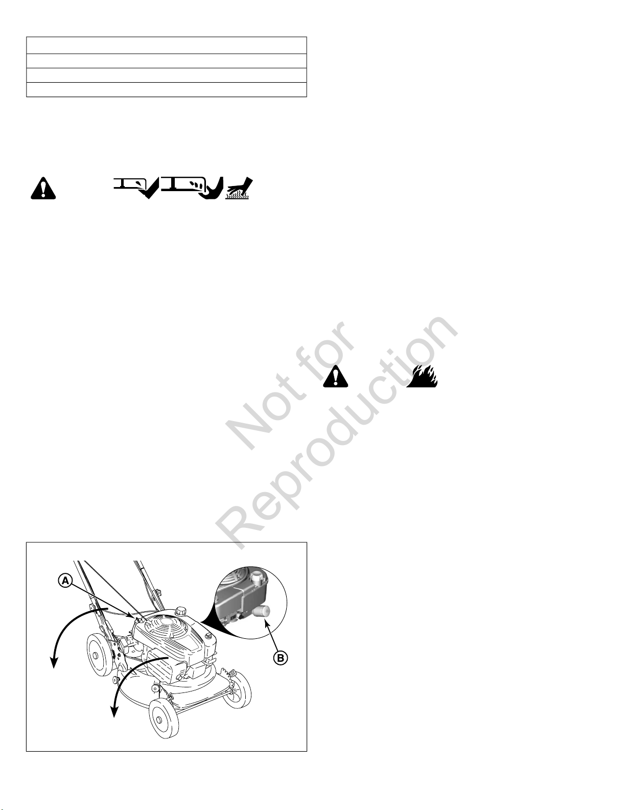
4. Check the engine oil:
• Make sure the mower is on a level surface.
• Clean the oil fill area of any debris.
• Remove the dipstick (A, Figure 4) and wipe with a clean
cloth.
• Insert and tighten the dipstick.
• Remove the dipstick and check the oil level. It should
be at the top of the full indicator (B) on the dipstick.
• If low, add oil slowly into the engine oil fill. See
Recommendations
wait one minute and recheck the oil level.
• Replace and tighten the dipstick.
.
Oil
. Do not overfill. After adding oil,
Mulching CoverA
Rear Height Adjustment Latch (2)B
Oil Fill Cap and DipstickC
Rope Start HandleD
8 www.snapper.com
Page 9
4
Not for
Reproduction
Synthetic 5W-30C.
5W-30D.
Fuel Recommendations
Fuel must meet these requirements:
• Clean, fresh, unleaded gasoline.
• A minimum of 87 octane / 87 AKI (91 RON). For high altitude
use, see below.
• Gasoline with up to 10% ethanol (gasohol) is acceptable.
5. Add fuel to the tank:
• Make sure the mower is outside, where fumes can
safely dissipate.
• Remove the fuel fill cap (C, Figure 4).
• Fill the tank with fuel. See
To allow for expansion of the fuel, do not fill above the
bottom of the filler neck (D).
• Reinstall the fuel fill cap.
6. Clean the exterior surfaces of the cutting deck and engine
of any accumulation of spilled fuel, dirt, grass, oil, etc. Keep
the engine air intake screen and cooling fins clear at all
times.
7. Charge the battery. See
Fuel Recommendations
Charging the Battery
.
.
Oil Recommendations
We recommend the use of Briggs & Stratton Warranty Certified
oils for best performance. Other high-quality detergent oils are
acceptable if classified for service SF, SG, SH, SJ or higher.
Do not use special additives.
NOTICE
and E85. Do not mix oil in gasoline or modify the engine to
run on alternate fuels. Use of unapproved fuels will cause
damage to engine components, which will not be covered
under warranty.
To protect the fuel system from gum formation, mix a fuel
stabilizer into the fuel. See Storage. All fuel is not the same. If
starting or performance problems occur, change fuel providers
or change brands. This engine is certified to operate on gasoline.
The emissions control system for this engine is EM (Engine
Modifications).
Do not use unapproved gasolines, such as E15
High Altitude
At altitudes over 5,000 feet (1524 meters), a minimum 85
octane/85 AKI (89 RON) gasoline is acceptable.
For carbureted engines, high altitude adjustment is required to
maintain performance. Operation without this adjustment will
cause decreased performance, increased fuel consumption,
and increased emissions. Contact a Briggs & Stratton Authorized
Service Dealer for high altitude adjustment information.
Operation of the engine at altitudes below 2,500 feet (762
meters) with the high altitude adjustment is not recommended.
For Electronic Fuel Injection (EFI) engines, no high altitude
adjustment is necessary.
Outdoor temperatures determine the proper oil viscosity for the
engine. Use the chart to select the best viscosity for the outdoor
temperature range expected.
SAE 30 - Below 40°F (4°C) the use of SAE 30 will result in hard
A.
starting.
10W-30 - Above 80°F (27°C) the use of 10W-30 may cause
B.
increased oil consumption. Check oil level more frequently.
9
Page 10
Starting the Mower
Not for
Reproduction
WARNING
Poisonous Gas Hazard
Engine exhaust contains carbon monoxide, a poisonous gas
that could kill you in minutes. You CANNOT see it, smell it,
or taste it. Even if you do not smell exhaust fumes, you could
still be exposed to carbon monoxide gas. If you start to feel
sick, dizzy, or weak while using this product, shut it off and
get to fresh air RIGHT AWAY. See a doctor. You may have
carbon monoxide poisoning.
• Operate this product ONLY outside far away from
windows, doors and vents to reduce the risk of carbon
monoxide gas from accumulating and potentially being
drawn towards occupied spaces.
• Install battery-operated carbon monoxide alarms or plug-in
carbon monoxide alarms with battery back-up according
to the manufacturer’s instructions. Smoke alarms cannot
detect carbon monoxide gas.
• DO NOT run this product inside homes, garages,
basements, crawlspaces, sheds, or other
partially-enclosed spaces even if using fans or opening
doors and windows for ventilation. Carbon monoxide can
quickly build up in these spaces and can linger for hours,
even after this product has shut off.
• ALWAYS place this product downwind and point the
engine exhaust away from occupied spaces.
5
Propelling the Mower
1. Start the mower.
2. Move the ground speed control (A, Figure 6) to the desired
speed position.
3. Squeeze the wheel drive control (B) against the handle to
engage the wheel drive and propel the mower forward.
Forward speed can be adjusted while the mower is moving
by changing the position of the ground speed control.
The engine on your mower is equipped with the Briggs &
Stratton Ready Start™ System. This features a
temperature-controlled automatic choke. No additional steps
are required to start a cold engine.
1. Move the engine speed control (A, Figure 5, if equipped)
to the fast (‘Rabbit’) position.
2. Squeeze the blade control (B) against the handle.
3. Start the mower:
• Manual Start Models: Pull the rope start handle (C) to
crank the engine.
• Electric Start Models: Insert the key (D) into the electric
start switch. Turn the key to crank the engine. Use short
starting cycles, five seconds maximum, and wait 1
minute between starting cycles.
4. To stop the engine (and blade), release the blade control.
5. After the engine starts, allow a brief warm-up until the engine
runs smooth before beginning mower operation.
6
Stopping the Mower
1. Stop forward motion of the mower by releasing the wheel
drive control.
2. Stop the engine and blade by releasing the blade control.
3. Electric Start Models: Remove the key from the electric start
switch.
10 www.snapper.com
Page 11
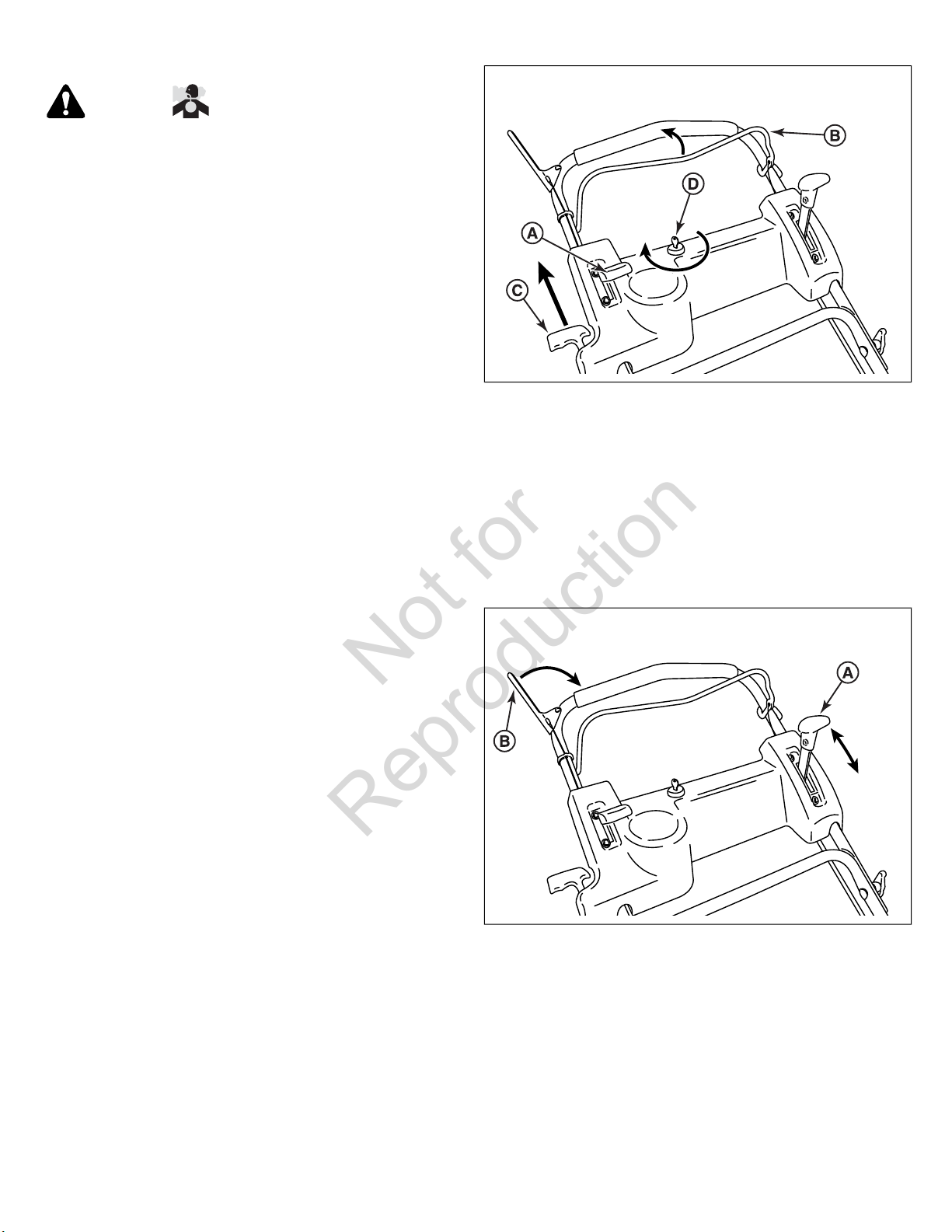
Handle Height Adjustment
Not for
Reproduction
Cutting Height Adjustment
WARNING
Amputation Hazard
• DO NOT attempt any maintenance, adjustments or service
with engine and blade running.
• STOP engine and blade.
• Disconnect spark plug wire and secure away from spark
plug.
Burn Hazard
• Engine and components are HOT.
• Avoid serious burns, allow sufficient time for all
components to cool.
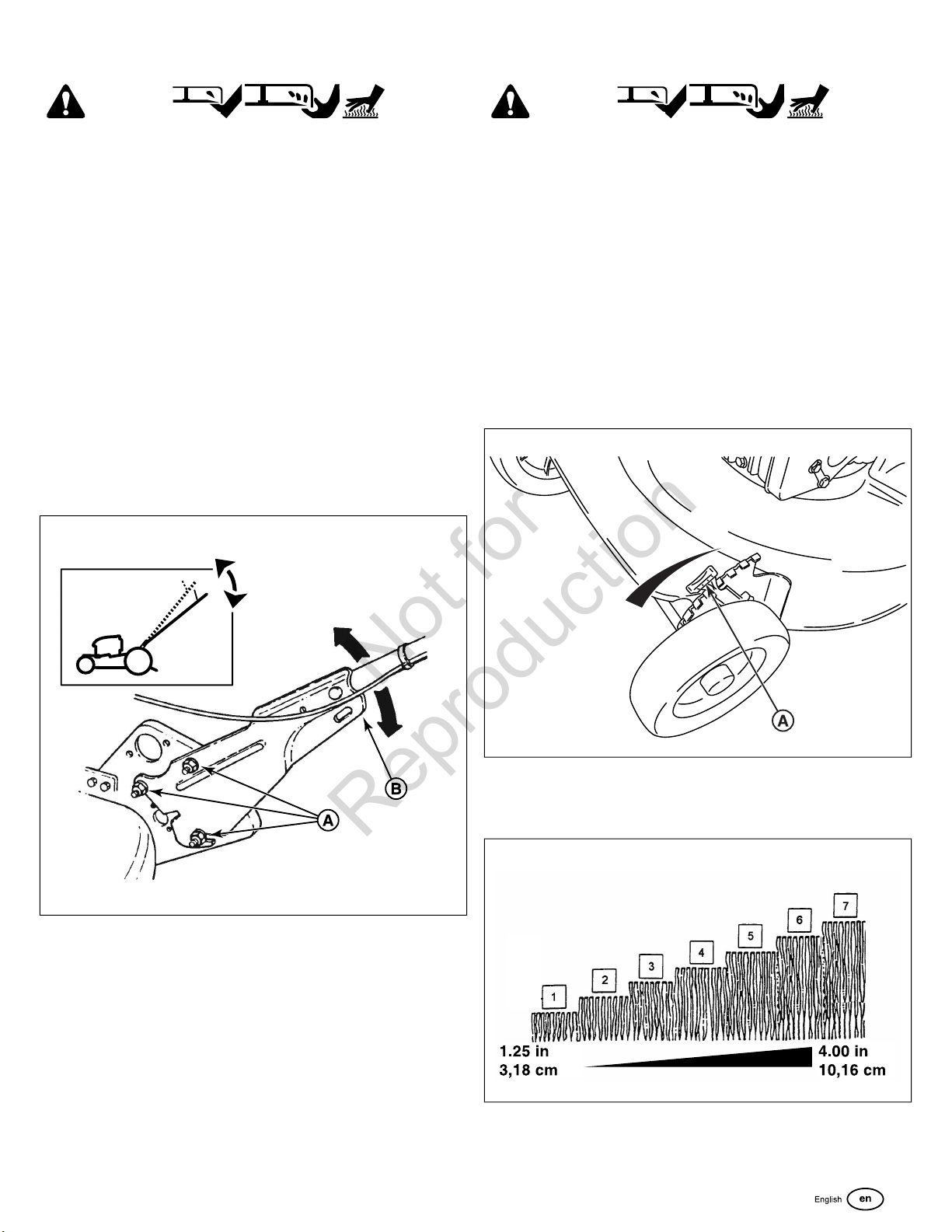
The height of the mower handle can be adjusted as follows:
1. Loosen the lower nuts (A, Figure 7) on each lower handle.
2. Move the handle assembly (B) up or down until the desired
position is achieved.
3. Tighten the lower nuts on each lower handle to maintain
the desired position.
7
WARNING
Amputation Hazard
• DO NOT attempt any maintenance, adjustments or service
with engine and blade running.
• STOP engine and blade.
• Disconnect spark plug wire and secure away from spark
plug.
Burn Hazard
• Engine and components are HOT.
• Avoid serious burns, allow sufficient time for all
components to cool.
1. Pull the height adjusting latch (A, Figure 8) outward and
move to the desired cutting height.
8
2. Set all wheels at the same cutting height. The highest cutting
position is Notch 7 (Figure 9). The lowest cutting position
is Notch 1.
9
11
Page 12
Mulching Operation
Not for
Reproduction
For best mulching results, cut up to a maximum of 1/3 of grass
blade length and recycle ONLY when grass is dry.
1. Set all wheels in the highest cutting position (Notch 7). See
Cutting Height Adjustment
2. Move the engine speed control to the fast (Rabbit) position.
3. Move the ground speed control to the slowest speed setting.
4. Proceed mowing slowly. If the grass is very dense, lower
each rear wheel latch one notch lower than the front wheel
latches to improve mulching performance.
.
Installing the Discharge Deflector
WARNING
Amputation Hazard
• DO NOT attempt any maintenance, adjustments or service
with engine and blade running.
• STOP engine and blade.
• Disconnect spark plug wire and secure away from spark
plug.
Burn Hazard
Note:
The mulching cover should remain on the machine at all
times, unless alternate discharge operations are desired, such
as side discharging or bagging.
Removing the Mulching Cover
(Optional Accessory on Some Models)
WARNING
Amputation Hazard
• DO NOT attempt any maintenance, adjustments or service
with engine and blade running.
• STOP engine and blade.
• Disconnect spark plug wire and secure away from spark
plug.
Burn Hazard
• Engine and components are HOT.
• Avoid serious burns, allow sufficient time for all
components to cool.
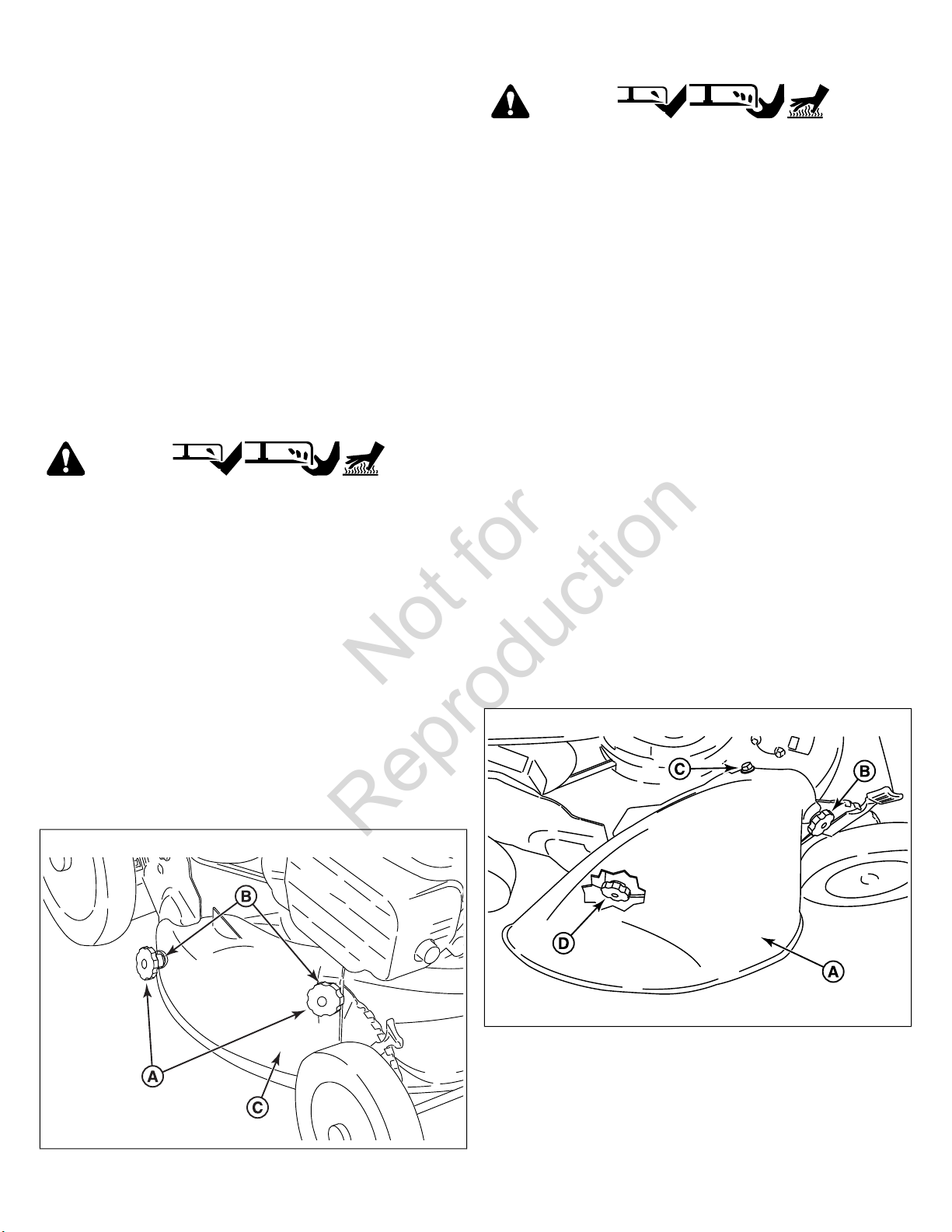
1. Remove the knob nuts (A, Figure 10) and internal/ external
tooth lock washers (B) securing the mulching cover (C) to
the mower deck.
2. Remove the cover.
• Engine and components are HOT.
• Avoid serious burns, allow sufficient time for all
components to cool.
1. Remove the mulching cover. See
2. Install the deflector (A, Figure 11) to the deck in place of
the mulching cover, making sure that:
• The front hole (B) on the outside front of the deflector
fits over the stud where the front of the mulching cover
was originally secured;
• The slot (C) on top of the deflector slips under the
restraining nut on top of the deck (under the right front
corner of the engine);
• The slot (D) on the inside rear of the deflector slips onto
the stud behind the rear of the discharge opening,
where the rear of the mulching cover was originally
secured.
3. Install the internal/external tooth lock washers and knob
nuts onto the studs and tighten securely.
Mulching Operation
11
.
10
12 www.snapper.com
Page 13
WARNING
Not for
Reproduction
Thrown Objects Hazard
DO NOT operate without entire Grass Catcher or guard in
place. Grass Catcher components are subject to deterioration
during normal use. Inspect frequently and replace worn or
damaged components immediately.
Installing the Grass Bag Adapter
(Optional Accessory on Some Models)
WARNING
Amputation Hazard
• DO NOT attempt any maintenance, adjustments or service
with engine and blade running.
• STOP engine and blade.
• Disconnect spark plug wire and secure away from spark
plug.
Burn Hazard
• Engine and components are HOT.
• Avoid serious burns, allow sufficient time for all
components to cool.
12
Installing the Mulching Plug
(Optional Accessory on Some Models)
1. Remove the mulching cover. See
Cover
.
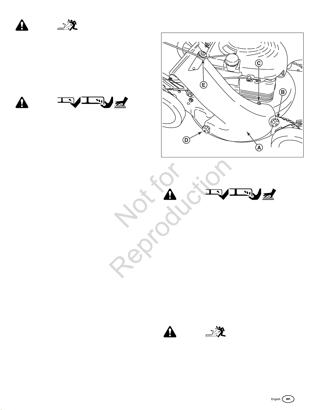
2. Install the adapter (A, Figure 12) to the deck in place of the
mulching cover, making sure that:
• The front hole (B) on the outside front of the adapter
fits over the stud where the front of the mulching cover
was originally secured;
• The slot (C) on top of the adapter slips under the
restraining nut on top of the deck (under the right front
corner of the engine);
• The slot (D) on the rear of the adapter slips onto the
stud behind the rear of the discharge opening, where
the rear of the mulching cover was originally secured.
3. Install the internal/external tooth lock washers and knob
nuts onto the studs and tighten securely.
4. Route the recoil rope around the outside of the rope guide
pulley (E).
Note:
The recoil rope may need to be slackened. See
the Mower
.
Removing the Mulching
Starting
WARNING
Amputation Hazard
• DO NOT attempt any maintenance, adjustments or service
with engine and blade running.
• STOP engine and blade.
• Disconnect spark plug wire and secure away from spark
plug.
Burn Hazard
• Engine and components are HOT.
• Avoid serious burns, allow sufficient time for all
components to cool.
1. Install the mulching plug (A, Figure 13) if mulching is desired
after the bag adapter is installed. Install the mulching plug
completely and securely into the bag adapter (B).
2. Install the grass bag as a safeguard and to further secure
the mulching plug.
WARNING
Thrown Objects Hazard
Install the grass bag when using the mulching plug. Failure
to do so may result in personal injury or death.
3. See
Mulching Operation
.
13
Page 14

13
Not for
Reproduction
Installing the Grass Bag
(Optional Accessory on Some Models)
WARNING
Amputation Hazard
• DO NOT attempt any maintenance, adjustments or service
with engine and blade running.
• STOP engine and blade.
• Disconnect spark plug wire and secure away from spark
plug.
14
WARNING
Unsafe Operation Hazard
Grass Catcher bags are made of woven fabric, and are subject
to deterioration and wear during normal usage. Check
condition of bag before each use. Immediately replace worn
or damaged catcher bags with only genuine replacement
bags. The grass catcher is optional equipment on some
models.
Burn Hazard
• Engine and components are HOT.
• Avoid serious burns, allow sufficient time for all
components to cool.
1. Install the grass bag adapter. See
Bag Adapter
2. Install the grass bag by sliding the connector (A, Figure 14)
over the adapter flange.
3. Attach the grass bag hooks (B) over the middle handle cross
bar.
.
Installing the Grass
Charging the Battery
(Optional Accessory on Some Models)
The battery provided with your mower is sealed and
maintenance-free. It requires no special care other than keeping
it properly charged. Use only the charger provided with your
mower when charging the battery.
Charge the battery after each use, and if the battery has been
stored for longer than 30 days. The time required to charge the
battery varies, but typically 16 to 24 hours will be sufficient to
bring the battery to a fully charged condition.
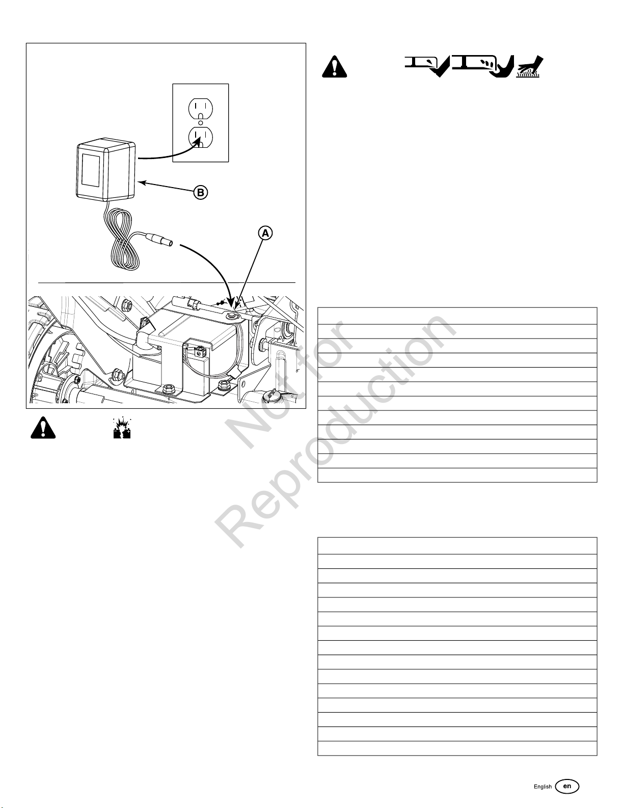
1. Remove the dust cap from the charger jack (A, Figure 15).
2. Plug the battery charger (B) into the charger jack.
3. Plug the charger into a 120-volt wall outlet.
4. Charge the battery for a period of 16 to 24 hours. (Longer
periods will not damage the battery.)
5. Unplug the charger from the wall outlet.
6. Unplug the charger from the charger jack.
7. Replace the dust cap onto the charger jack.
14 www.snapper.com
Page 15
15
Not for
Reproduction
WARNING
Explosion Hazard
Avoid Serious Injury and Property Damage.
• DO NOT attempt to charge this battery with automotive
or ‘Boost’ chargers.
• DO NOT attempt to jump start a mower that has a dead
battery.
• Always use the charger supplied with this mower to charge
this battery.
Maintenance
Emissions Control Service
Maintenance, replacement, or repair of the emissions
control devices and systems may be performed by any
off-road engine repair establishment or individual. However,
to obtain "no charge" emissions control service, the work must
be performed by a factory authorized dealer. See the Emissions
Control Statements.
Maintenance Chart
WARNING
Amputation Hazard
• DO NOT attempt any maintenance, adjustments or service
with engine and blade running.
• STOP engine and blade.
• Disconnect spark plug wire and secure away from spark
plug.
Burn Hazard
• Engine and components are HOT.
• Avoid serious burns, allow sufficient time for all
components to cool.
Laceration Hazard
• Wear heavy leather gloves when handling or working
around cutting blades.
• Blades are extremely sharp and can cause severe injury.
MOWER
Every 8 Hours or Daily
Check safety interlock system
Clean debris off mower
Every 25 Hours or Annually *
Check mower for loose hardware
See Dealer Annually to
Lubricate mower
Check mower blade **
Check mower blade stopping time
Check drive belt
Clean battery and cables
* Whichever comes first
** Check blade more often in regions with sandy soils or high
dust conditions
ENGINE
First 5 Hours
Change engine oil
Every 8 Hours or Daily
Check engine oil level
Every 25 Hours or Annually *
Clean engine air filter and pre-cleaner (if equipped) **
Every 50 Hours or Annually *
Change engine oil
Replace oil filter (if equipped)
Annually
Replace air filter
Replace pre-cleaner (if equipped)
See Dealer Annually to
Inspect muffler and spark arrester (if equipped)
15
Page 16
ENGINE
Not for
Reproduction
Replace spark plug
Replace fuel filter (if equipped)
Clean engine air cooling system
* Whichever comes first
** Clean more often in dusty conditions or when airborne debris
is present
Change Engine Oil
WARNING
Amputation Hazard
• DO NOT attempt any maintenance, adjustments or service
with engine and blade running.
• STOP engine and blade.
• Disconnect spark plug wire and secure away from spark
plug.
Burn Hazard
• Engine and components are HOT.
• Avoid serious burns, allow sufficient time for all
components to cool.
Laceration Hazard
NOTICE
Drain the fuel tank before tipping the machine. DO NOT tip
the machine with the carburetor or spark plug down. Oil from
the crankcase will saturate the air filter and cause the engine
to be hard to start or not start at all. If contamination does
occur, the air filter will have to be replaced.
Change Oil Filter
(If Equipped)
1. Drain the oil from the engine. See
2. Remove the oil filter (B, Figure 16) and dispose of properly.
3. Before you install the new oil filter, lightly lubricate the oil
filter gasket with fresh, clean oil.
4. Install the oil filter by hand until the gasket contacts the oil
filter adapter, then tighten the oil filter 1/2 to 3/4 turns.
5. Add oil. See
6. Start and run the engine. As the engine warms up, check
for oil leaks.
7. Stop the engine and check the oil level. It should be at the
top of the full indicator on the dipstick.
Change Engine Oil
Change Engine Oil
.
.
Service Air Filter
• Wear heavy leather gloves when handling or working
around cutting blades.
• Blades are extremely sharp and can cause severe injury.
1. Drain the fuel tank completely.
2. Remove the dipstick (A, Figure 16), then turn the mower
on its side. Allow the oil to drain from the oil fill tube into an
appropriate container. Dispose of used oil properly.
3. Place the mower upright, then fill the engine with engine oil
to the ‘full’ mark on the dipstick. Refer to the section entitled
‘Oil Recommendations’. Do not overfill.
16
WARNING
Fire Hazard
Never start or run the engine with the air cleaner assembly (if
equipped) or the air filter (if equipped) removed.
NOTICE
Do not use pressurized air or solvents to clean the filter.
Pressurized air can damage the filter and solvents will dissolve
the filter.
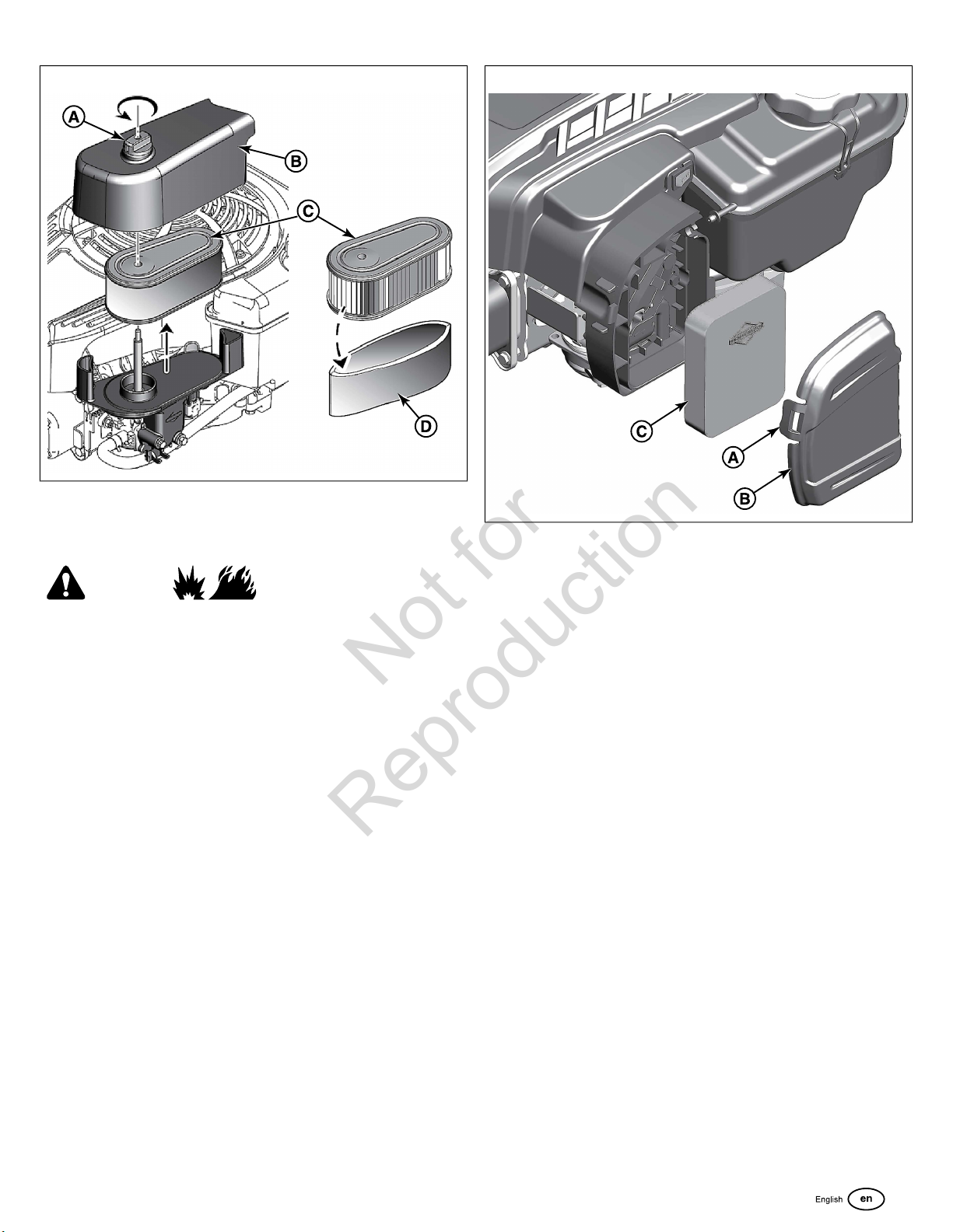
1. Remove the fastener (A, Figure 17) and the air filter cover
(B).
2. Remove the pre-cleaner (C) and the filter (D).
3. To loosen debris, gently tap the filter on a hard surface. If
the filter is excessively dirty, replace with a new filter.
4. Wash the pre-cleaner in liquid detergent and water. Then
allow it to thoroughly air dry. Do not oil the pre-cleaner.
5. Assemble the dry pre-cleaner to the filter.
6. Install the filter and pre-cleaner into the base (E). Make sure
filter fits securely in the base.
7. Install air filter cover and secure with fastener. Make sure
the fastener is tight.
16 www.snapper.com
Page 17
17
Not for
Reproduction
Service Air Filter
See Figure: 18, 19
WARNING
Fuel and its vapors are extremely flammable and
explosive.
Fire or explosion can cause severe burns or death.
• Never start and run the engine with the air cleaner assembly
(if equipped) or the air filter (if equipped) removed.
NOTICE
filter. Pressurized air can damage the filter and solvents will
dissolve the filter.
See the
Do not use pressurized air or solvents to clean the
Maintenance Schedule
for service requirements.
18
2. Remove the cover (B, Figure 18).
3. To prevent debris from falling into the carburetor, carefully
remove the foam element (C, Figure 18) from the air filter
base.
4. Wash the foam element (C, Figure 18) in liquid detergent
and water. Squeeze dry the foam element in a clean cloth.
5. Saturate the foam element (C, Figure 18) with clean engine
oil. To remove the excess engine oil, squeeze the foam
element in a clean cloth.
6. Install the foam element (C, Figure 18) onto the air filter
base.
7. Install the cover (B, Figure 18) and secure with fastener(s)
(A).
Various models use either a foam or a paper filter. Some models
may also have an optional pre-cleaner that can be washed and
reused. Compare the illustrations in this manual with the type
installed on your engine and service as follows.
Foam Air Filter
1. Open the fastener(s) (A, Figure 18).
Paper Air Filter
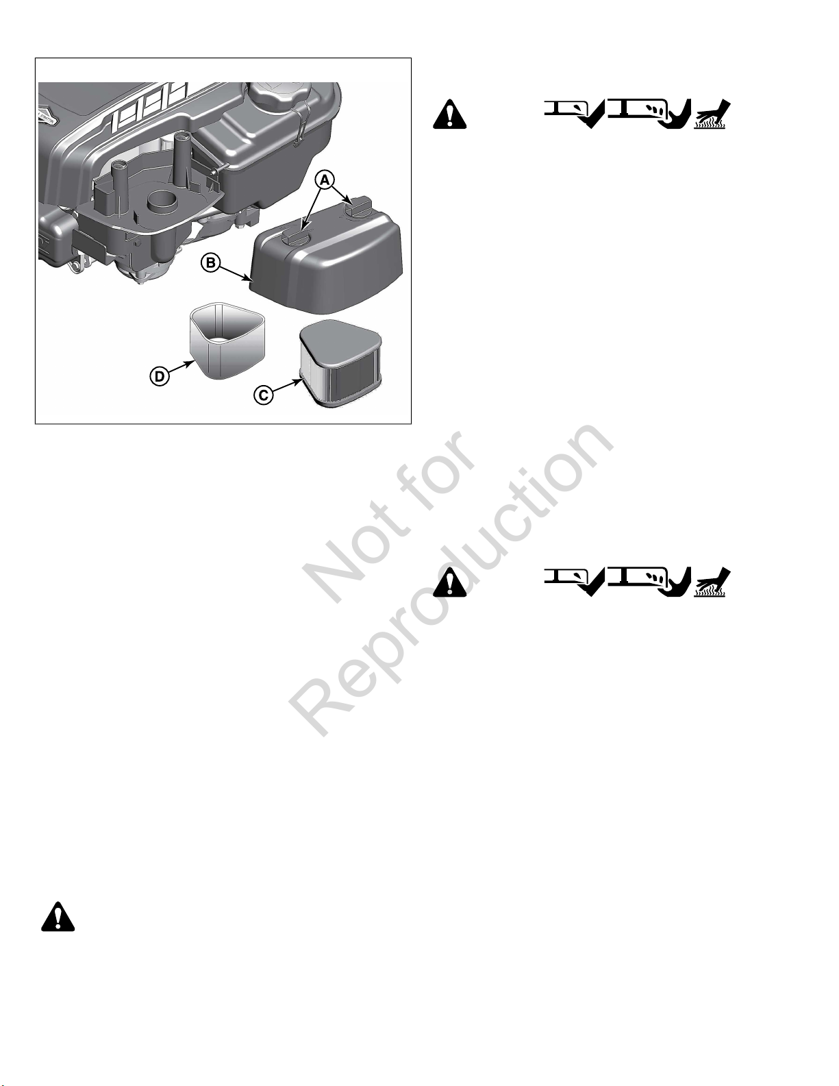
1. Loosen the fastener(s) (A, Figure 19).
17
Page 18
19
Not for
Reproduction
Clean Debris Off Mower
WARNING
Amputation Hazard
• DO NOT attempt any maintenance, adjustments or service
with engine and blade running.
• STOP engine and blade.
• Disconnect spark plug wire and secure away from spark
plug.
Burn Hazard
• Engine and components are HOT.
• Avoid serious burns, allow sufficient time for all
components to cool.
Laceration Hazard
• Wear heavy leather gloves when handling or working
around cutting blades.
• Blades are extremely sharp and can cause severe injury.
2. Remove the cover (B, Figure 19).
3. To prevent debris from falling into the carburetor, carefully
remove the pre-cleaner (D, Figure 19) and the filter (C) from
the air filter base.
4. Remove the pre-cleaner (D, Figure 19), if equipped, from
the filter (C).
5. To loosen debris, gently tap the filter (C, Figure 19) on a
hard surface. If the filter is excessively dirty, replace with a
new filter.
6. Wash the pre-cleaner (D, Figure 19), if equipped, in liquid
detergent and water. Allow the pre-cleaner to throughly air
dry. Do not oil the pre-cleaner.
7. Assemble the dry pre-cleaner (D, Figure 19), if equipped,
to the filter (C).
8. Install the filter (C, Figure 19) and the pre-cleaner (D), if
equipped, onto the air filter base. Make sure the filter fits
securely on the air filter base.
9. Install the cover (B, Figure 19) and secure with the
fastener(s) (A). Make sure the fastener(s) is tight.
Check Safety Interlock System
1. Start the mower.
2. Release the blade control. The engine must stop within 3
seconds.
1. Clean dirt and debris from the top of the mower deck.
2. Clean any debris buildup on or around the engine, etc.
While cleaning, check components for wear or damage. Replace
worn or damaged components immediately.
Storage Procedure
WARNING
Amputation Hazard
• DO NOT attempt any maintenance, adjustments or service
with engine and blade running.
• STOP engine and blade.
• Disconnect spark plug wire and secure away from spark
plug.
Burn Hazard
• Engine and components are HOT.
• Avoid serious burns, allow sufficient time for all
components to cool.
Laceration Hazard
• Wear heavy leather gloves when handling or working
around cutting blades.
• Blades are extremely sharp and can cause severe injury.
Prepare the mower for end-of-season storage as follows:
WARNING
Unsafe Operation Hazard
If the engine does not stop within 3 seconds, do not use the
mower. Bring the mower to an authorized dealer for service.
18 www.snapper.com
1. Disconnect the spark plug wire and secure away from the
spark plug.
2. Drain the fuel tank and let the engine run until all fuel is out
of the carburetor.
Page 19
Note:
Not for
Reproduction
If using a fuel stabilizer, there is no need to drain the fuel
tank. See
3. Use a brush or compressed air to remove loose debris, then
4. Tilt the mower up on its rear wheels and inspect the
5. Lubricate all exposed metal with a light coating of oil to
6. Carefully fold the handles, flexing the control cables to
7. Store the mower in a shed or other dry area, protected from
Fuel System
use a damp cloth to wipe down the unit.
underside of the deck. (Do not tilt the mower with the spark
plug or carburetor down.) Scrape away stubborn
accumulation of grass with a putty knife and/or wire brush.
prevent corrosion.
prevent cable damage.
weather.
.
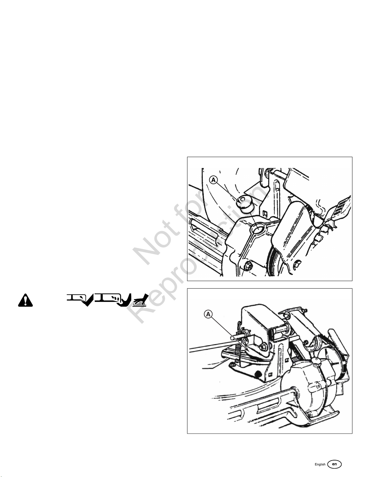
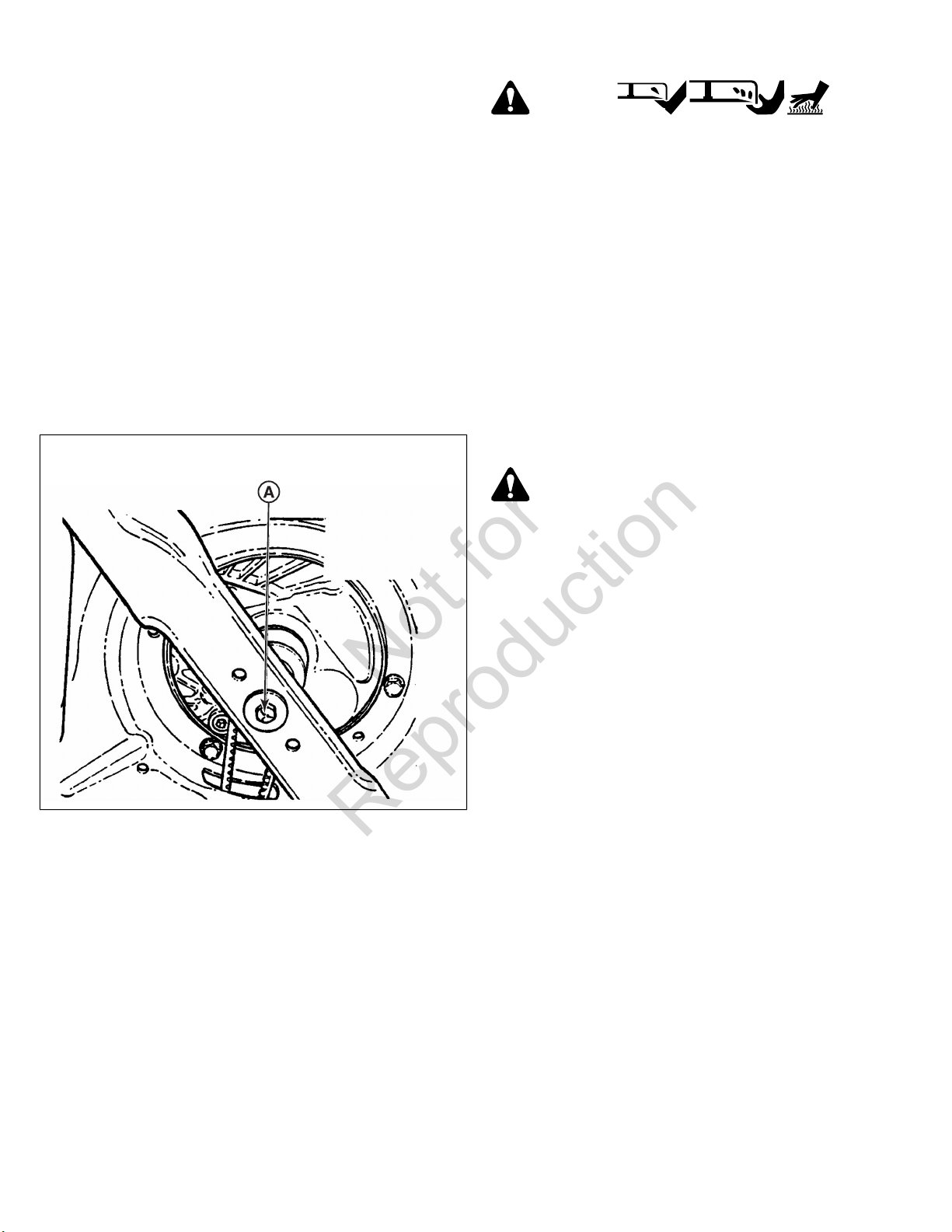
Check Grease Level in Transmission
1. Remove the transmission fill plug (A, Figure 20). Roll the
machine forward or backward while looking down into the
plug hole.
2. If liquid grease is not visible on the input gear (the small
gear below the plug hole), add an amount, to cover the
gear, of Snapper “00” grease.
Note:
Snapper “00” grease (Part No. 7029443) is available at
your dealer.
Note:
Do not spill grease or oil onto the surface of the drive disc
(A, Figure 21).
3. Reinstall the transmission plug.
4. Check the grease level after each 25 hours of operation.
Fuel System
Fuel can become stale when stored over 30 days. Stale fuel
causes acid and gum deposits to form in the fuel system or on
essential carburetor parts. To keep fuel fresh, use Briggs &
Stratton Advanced Formula Fuel Treatment & Stabilizer,
available wherever Briggs & Stratton genuine service parts are
sold.
There is no need to drain gasoline from the engine if a fuel
stabilizer is added according to instructions. Run the engine for
two (2) minutes to circulate the stabilizer throughout the fuel
system before storage.
If gasoline in the engine has not been treated with a fuel
stabilizer, it must be drained into an approved container. Run
the engine until it stops from lack of fuel. The use of a fuel
stabilizer in the storage container is recommended to maintain
freshness.
Service
WARNING
Amputation Hazard
• DO NOT attempt any maintenance, adjustments or service
with engine and blade running.
• STOP engine and blade.
• Disconnect spark plug wire and secure away from spark
plug.
20
21
Burn Hazard
• Engine and components are HOT.
• Avoid serious burns, allow sufficient time for all
components to cool.
Laceration Hazard
• Wear heavy leather gloves when handling or working
around cutting blades.
• Blades are extremely sharp and can cause severe injury.
19
Page 20
Check Mower Blade
Not for
Reproduction
Mower Blade Replacement
1. Disconnect the spark plug wire and secure the end away
from the plug.
2. Tilt the mower up on its rear wheels for access to the blade
cap screw (A, Figure 22). Do not tilt the mower with the
spark plug or carburetor down.
NOTICE
Drain the fuel tank before tipping the mower. DO NOT tip the
machine with the carburetor or spark plug down. Oil from the
crankcase will saturate the air filter and cause the engine to
be hard to start or not start at all. If contamination does occur,
the air filter will have to be replaced.
3. Check the torque of the blade cap screw. Recommended
torque: 40 lb-ft (54 Nm).
4. Check the blade for sharpness, wear and damage. See
Blade Wear Limits
.
22
WARNING
Amputation Hazard
• DO NOT attempt any maintenance, adjustments or service
with engine and blade running.
• STOP engine and blade.
• Disconnect spark plug wire and secure away from spark
plug.
Burn Hazard
• Engine and components are HOT.
• Avoid serious burns, allow sufficient time for all
components to cool.
Laceration Hazard
• Wear heavy leather gloves when handling or working
around cutting blades.
• Blades are extremely sharp and can cause severe injury.
WARNING
Unsafe Operation Hazard
Check Engine Drive Belt
• Visually check the engine drive belt for cracking, fraying,
severed or exposed belt strands. If worn or damaged,
replace the belt before operating the mower.
Check Transmission Drive Belt
• Visually check the poly-v belt for cracking, fraying, severed
or exposed belt strands. If worn or damaged, replace the
belt before operating the mower.
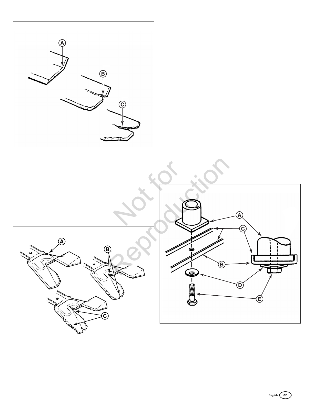
DO NOT use a cutting blade that shows signs of excessive wear
or damage.
Standard Blade Wear Limit
1. Inspect the blade (Figure 23) frequently for signs of
excessive wear or damage:
• (A) New blade
• (B) Wear limit (notch starts)
• (C) Dangerous condition! Do not use on the mower!
Replace with a new blade.
20 www.snapper.com
Page 21
23
Not for
Reproduction
Ninja Blade Wear Limit
1. Inspect the blade (Figure 24) frequently for signs of
excessive wear or damage:
NOTICE
Drain the fuel tank before tipping the mower. DO NOT tip the
machine with the carburetor or spark plug down. Oil from the
crankcase will saturate the air filter and cause the engine to
be hard to start or not start at all. If contamination does occur,
the air filter will have to be replaced.
3. Remove the blade (B, Figure 25).
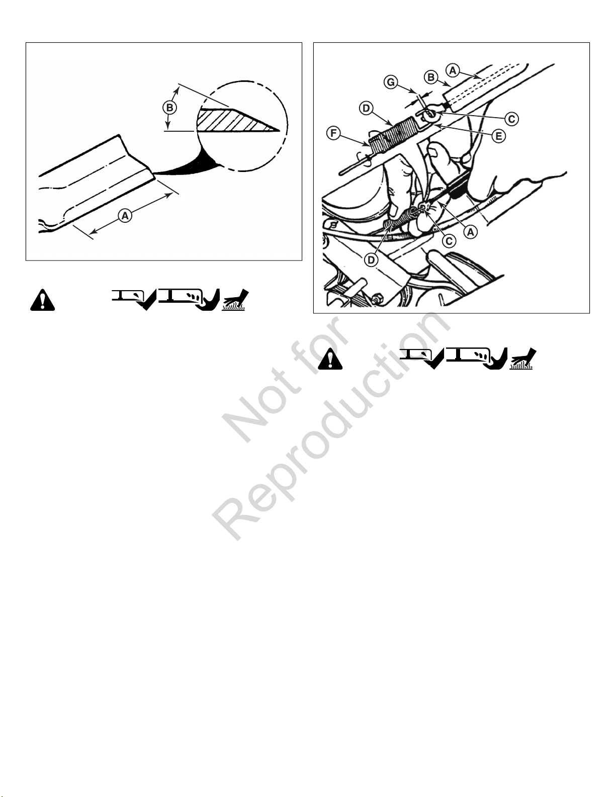
4. Sharpen the blade on a grinding wheel at an angle of 22 to
28 degrees (B, Figure 26). DO NOT sharpen the blade
beyond the original cutting edge (A).
5. Check blade for balance. If necessary, correct balance by
grinding heavy end of blade.
6. Reinstall blade (B, Figure 25). Note the correct assembly
order:
• (A) Blade hub
• (B) Blade
• (C) Blade flange (facing up)
• (D) Cone washer (concave side up)
• (E) Capscrew
7. Check torque of blade retaining cap screw. Recommended
torque: 40 lb-ft (54 Nm).
• (A) New blade
• (B) Wear limit (cracks or notches begin to appear on
tip)
• (C) Dangerous condition! Do not use on the mower!
Replace with a new blade.
24
25
Blade Sharpening
1. Disconnect the spark plug wire and secure the end away
from the plug.
2. Tilt the mower up on its rear wheels. Do not tilt the mower
with the spark plug or carburetor down.
21
Page 22
26
Not for
Reproduction
Wheel Drive Control Adjustment
WARNING
Amputation Hazard
27
• DO NOT attempt any maintenance, adjustments or service
with engine and blade running.
• STOP engine and blade.
• Disconnect spark plug wire and secure away from spark
plug.
Burn Hazard
• Engine and components are HOT.
• Avoid serious burns, allow sufficient time for all
components to cool.
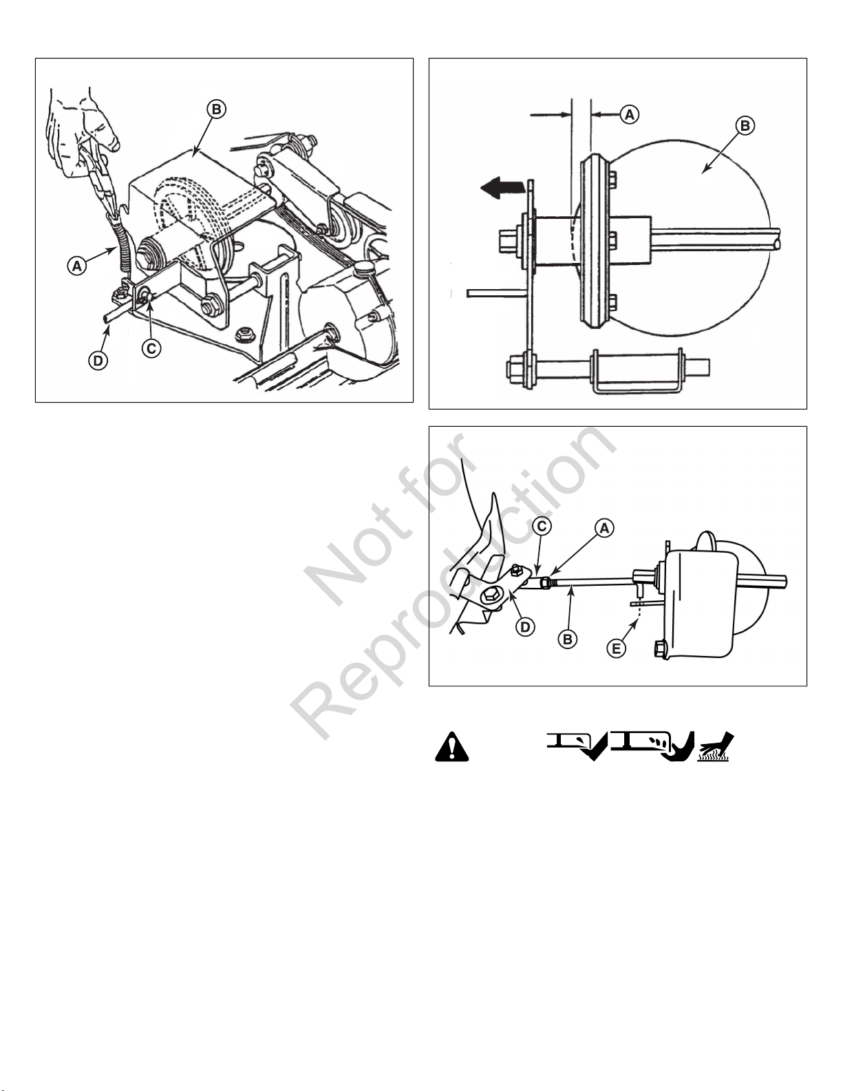
1. The wheel drive control is properly adjusted when there is
1/16” to 1/8” (1.6 - 3.2 mm) clearance (G, Figure 27)
between the inside of the spring hook (E) and the inside of
the clutch cable eye (C) with the wheel drive control
released.
2. To adjust, unhook the upper spring (D) from the cable eye
and rotate the spring in the direction required to extend or
shorten the spring length.
3. Rehook the upper spring to the cable eye and check
clearance. Repeat the procedure if required.
Note:
The vinyl spring cover (B) should be kept over the spring
at all times except for adjustments.
4. If the wheel drive control fails to return quickly to the OFF
position when released, check for binding at the cable
holdings located on the side of the right handle. The upper
clip should be located 2” (5 cm) below the upper knob; the
lower clip should be 4” (10 cm) above the lower knob. The
cable should slide freely with the clips installed at these
locations.
Driven and Drive Disc Service
WARNING
Amputation Hazard
• DO NOT attempt any maintenance, adjustments or service
with engine and blade running.
• STOP engine and blade.
• Disconnect spark plug wire and secure away from spark
plug.
Burn Hazard
• Engine and components are HOT.
• Avoid serious burns, allow sufficient time for all
components to cool.
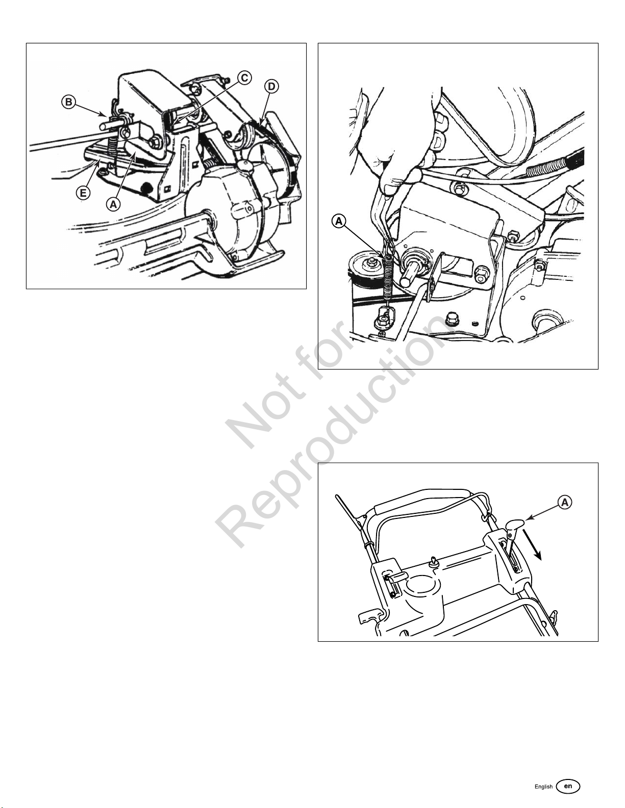
If the mower does not propel itself properly, check for the
following problems:
1. Grease on the drive disc (A, Figure 28) causing slippage.
2. Broken or disconnected drive spring (B).
3. Driven disc (C) is out of adjustment.
4. Driven disc rubber is worn - does not contact drive disc
properly.
5. Worn Poly-V belt (D) or engine drive belt (E).
22 www.snapper.com
Page 23
28
Not for
Reproduction
If any of the above (1 thru 5) are causing problems, service as
follows:
Cleaning Drive Disc and Driven Disc
If oil or grease on the drive disc or driven disc is causing
slippage, clean the discs as follows:
29
1. Wipe away any oil or grease with a clean cloth.
2. Use either an approved grease solvent or hot, soapy water
to clean drive disc or driven disc.
3. Rinse components with clean water.
4. Dry components with a clean cloth.
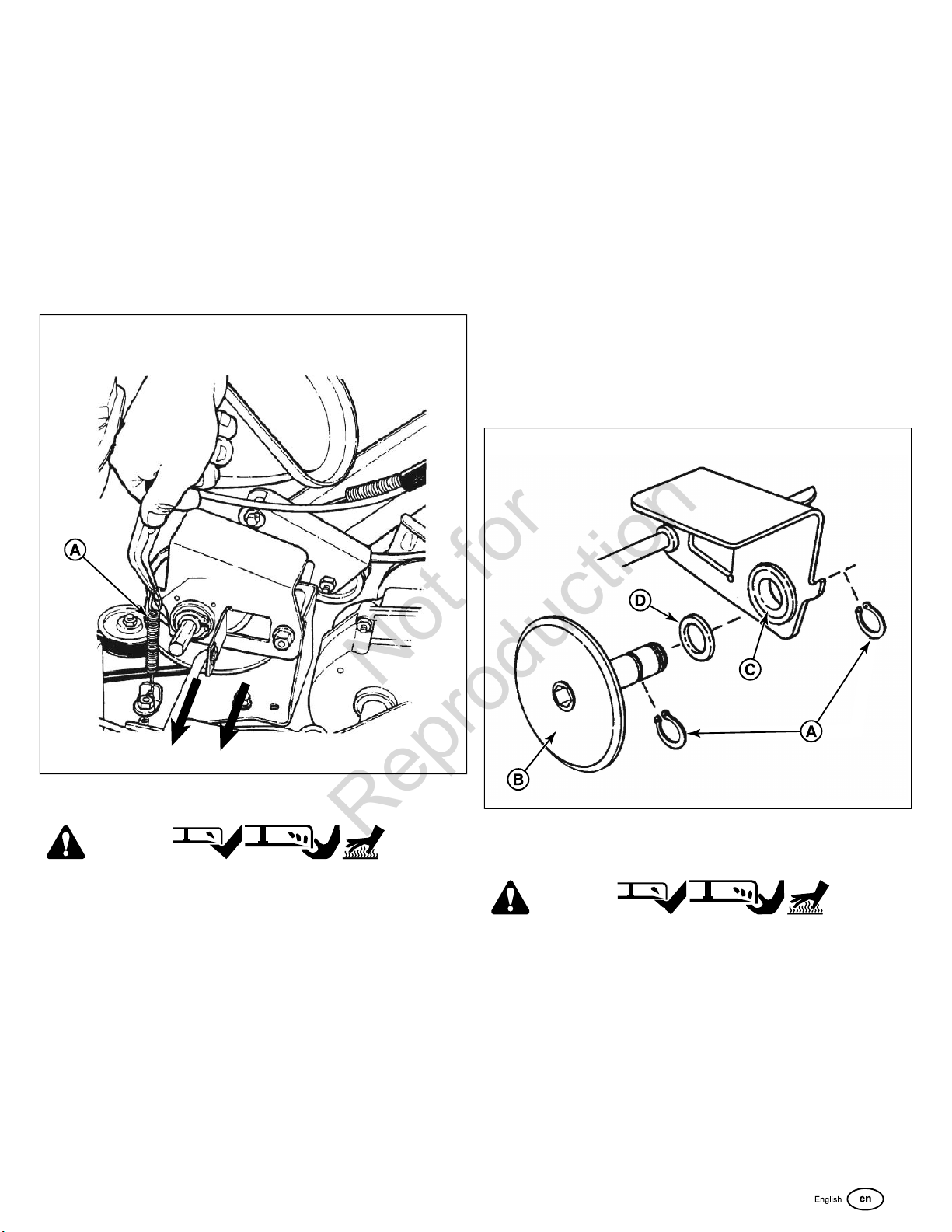
Drive Spring Repair / Replacement
If the drive spring (A, Figure 29) is loose, reconnect. If the spring
is broken, replace with a new spring.
Note:
Use a pair of needle nose pliers to install the drive spring.
If the drive system continues slipping, see
Troubleshooting
Driven Disc Adjustment
If the drive disc and driven disc are clean and the mower drive
is still slipping, adjust the driven disc as follows:
1. Move the ground speed control (A, Figure 30) into the FAST
position.
30
.
2. Remove the driven disc spring (A, Figure 31) from the driven
disc assembly (B). Also remove the pin and washer (C)
from the transfer rod (D), and remove the end of the transfer
rod from the hole in the driven disc assembly.
23
Page 24
31
Not for
Reproduction
3. Slide the driven disc assembly over to 1/8” (3.2 mm) (A,
Figure 32) from the outside edge of the drive disc (B).
4. Loosen the jam nut (A, Figure 33) securing the transfer rod
(B) to the ball joint (C) on the pivot bracket (D).
5. Turn the rod in or out of the ball joint until the end of the rod
aligns with the hole (E) in the driven disc assembly from
which the rod was removed.
32
33
Note:
Do not move the pivot bracket.
6. Reinstall the rod as removed in Step 2. Move the ground
speed control to the SLOW position, then back to the FAST
position. Recheck the 1/8” (3.2 mm) measurement described
previously. Readjust as needed. Tighten the nut when
finished.
7. Reinstall the driven disc spring to the driven disc assembly.
Driven Disc Replacement
WARNING
Amputation Hazard
• DO NOT attempt any maintenance, adjustments or service
with engine and blade running.
• STOP engine and blade.
• Disconnect spark plug wire and secure away from spark
plug.
Burn Hazard
• Engine and components are HOT.
• Avoid serious burns, allow sufficient time for all
components to cool.
If the rubber on the driven disc is badly chunked or worn, it must
be replaced. Install a new driven disc as follows:
24 www.snapper.com
Page 25
1. Remove the pin and washer (C, Figure 31) from the transfer
Not for
Reproduction
rod (D), and remove the end of the transfer rod from the
hole in the driven disc assembly.
2. Using needle nose pliers, unhook the drive spring (A, Figure
34) and slide the driven disc assembly off the hex shaft.
3. Remove the two snap rings (A, Figure 35) which secure the
rubber driven disc (B) to the driven disc assembly.
4. Install a new rubber driven disc onto the driven disc
assembly, and secure with the retaining rings.
5. Reverse the above procedures for reassembly and
installation of the driven disc assembly.
34
punch. A new bearing with four retaining screws will have to be
purchased to replace existing bearing.
If the driven disc bearing requires replacement, replace the
bearing as follows:
1. Remove the driven disc assembly. See
Replacement
2. Remove both snap rings (A, Figure 35) that secure the
rubber driven disc (B) to the thrust plate.
3. Slide the rubber driven disc hub out of the bearing.
4. Drive out the existing bearing (C).
5. Install a new bearing and secure to the thrust plate with four
retaining screws. Tighten the screws securely.
6. Reassemble the components in reverse order.
Note:
Be sure to replace the shim washer (D) when
reassembling the driven disc assembly.
.
Driven Disc
35
Driven Disc Bearing Replacement
WARNING
Amputation Hazard
• DO NOT attempt any maintenance, adjustments or service
with engine and blade running.
• STOP engine and blade.
• Disconnect spark plug wire and secure away from spark
plug.
Burn Hazard
• Engine and components are HOT.
• Avoid serious burns, allow sufficient time for all
components to cool.
The bearing on these machines is staked into the thrust plate.
The bearing will have to be driven out with a mallet and a large
Replacing the Bearing on the Pulley End of the Hex
Shaft
WARNING
Amputation Hazard
• DO NOT attempt any maintenance, adjustments or service
with engine and blade running.
• STOP engine and blade.
• Disconnect spark plug wire and secure away from spark
plug.
Burn Hazard
• Engine and components are HOT.
• Avoid serious burns, allow sufficient time for all
components to cool.
25
Page 26
The bearing on these machines is staked into the thrust plate.
Not for
Reproduction
The bearing will have to be driven out with a mallet and a large
punch. A new bearing with four retaining screws will have to be
purchased to replace existing bearing.
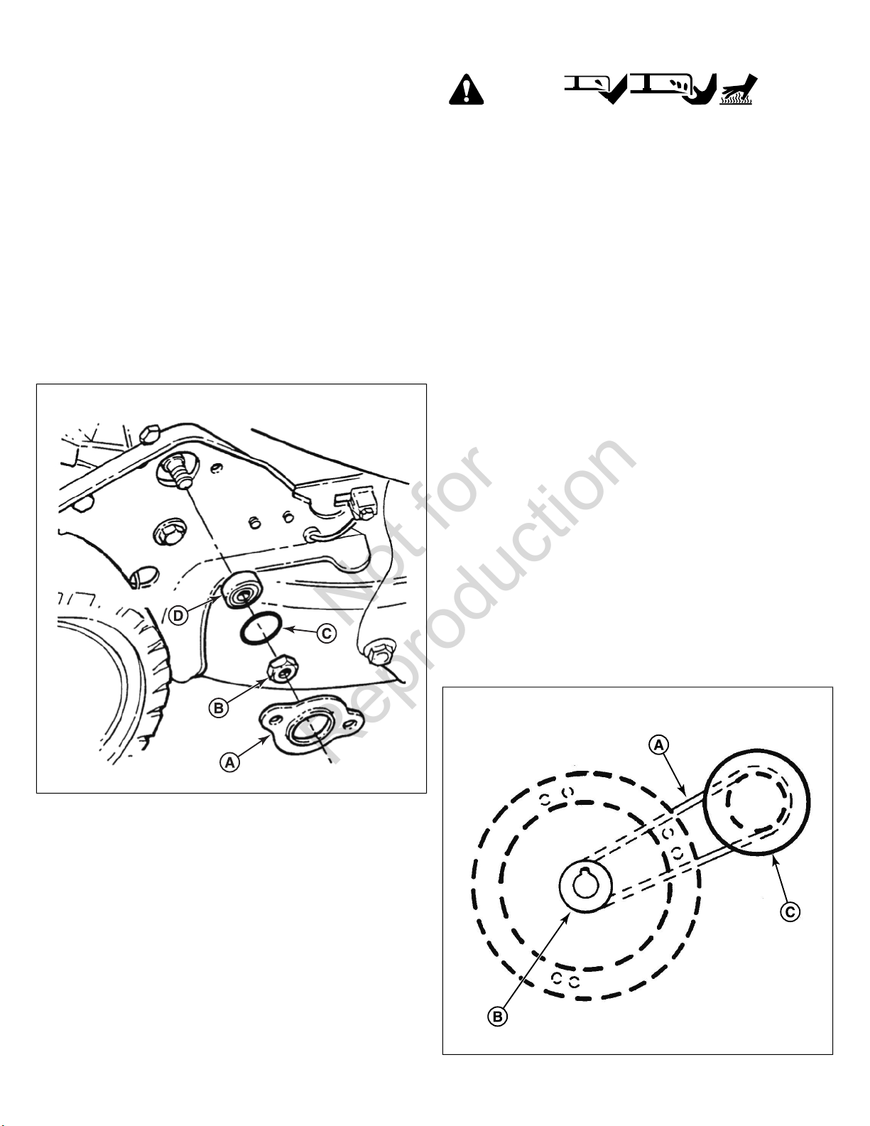
To replace the bearing on the pulley end of the hex shaft:
1. Hold the hex shaft with an adjustable wrench held next to
the pulley.
2. Remove the 3/8” hex lock nut (B, Figure 36), located on the
outside of the right wheel bracket.
3. Remove the holder (A), O-ring (C) and bearing (D).
4. Install the new bearing.
5. Carefully install the new O-ring over the outside of the new
bearing.
6. Install the bearing holder, and secure with screws.
7. Install the 3/8” hex lock nut.
36
Belt Service
WARNING
Amputation Hazard
• DO NOT attempt any maintenance, adjustments or service
with engine and blade running.
• STOP engine and blade.
• Disconnect spark plug wire and secure away from spark
plug.
Burn Hazard
• Engine and components are HOT.
• Avoid serious burns, allow sufficient time for all
components to cool.
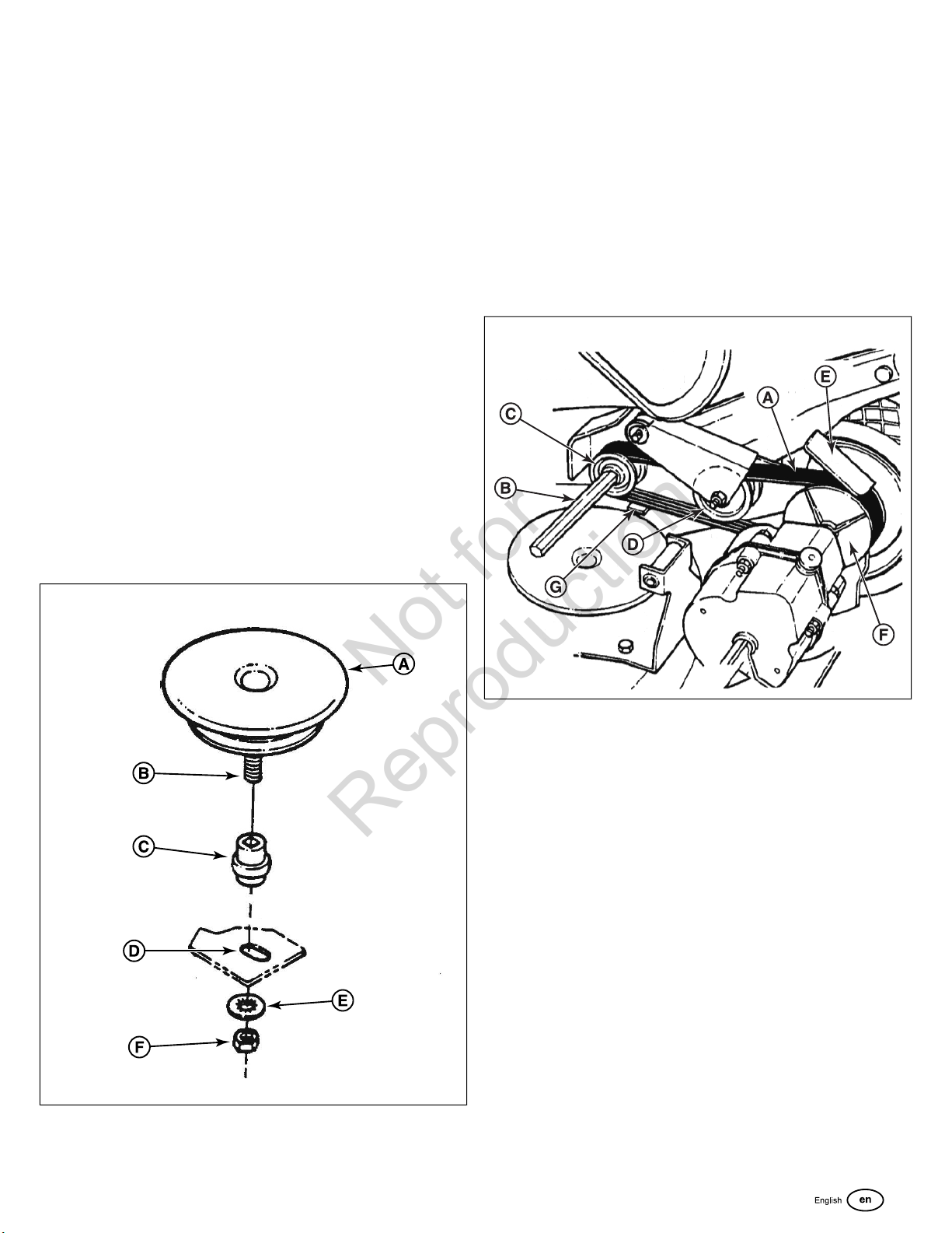
On self-propelled mowers, the engine belt (A, Figure 37)
transmits power from the engine pulley (B) to the drive disc (C).
The drive disc powers the poly-v belt, which engages the
transmission that powers the rear wheels. Should these belts
become worn, they could cause slippage, which would impair
mower performance. The condition of the engine belt and poly-v
belt should be checked after every 25 hours of mower operation.
Engine Drive Belt Replacement (Stretch Type Belts)
1. Empty the fuel tank.
2. Note the belt routing (Figure 37). There is no idler pulley on
these models to disconnect.
NOTICE
Drain the fuel tank before tipping the mower. DO NOT tip the
machine with the carburetor or spark plug down. Oil from the
crankcase will saturate the air filter and cause the engine to
be hard to start or not start at all. If contamination does occur,
the air filter will have to be replaced.
37
26 www.snapper.com
Page 27
3. Remove the driven disc. See
Not for
Reproduction
for driven disc removal procedure.
4. Drain the fuel tank before tipping the mower. Do not tilt the
mower with the spark plug or carburetor down. Tilt the
mower up on its rear wheels and remove the blade and
blade hub. Assistance from another person may be
necessary to hold the mower in the tilted position.
5. Hold the slotted end of the drive disc bolt (B, Figure 38) with
a screwdriver and remove the nut (F) and internal tooth lock
washer (E).
6. Remove the belt cover, located under the deck.
7. Lift the drive disc (A) up and remove the worn belt.
8. Loop one end of the new belt over the engine pulley and
insert the other end through the slot in the deck.
9. Loop the belt around the pulley on the bottom of the drive
disc.
10. Reinstall the drive disc and retaining hardware.
Note:
1) The square shoulder of the drive disc bolt must fit into
the square hole of the bushing (C). 2) The square end of the
bushing must fit into the bracket slot (D).
11. Reinstall the belt cover and tighten the bolts securely.
12. Reinstall the blade hub and cutter blade. Recommended
torque for the blade cap screw is 40 lb-ft (54 Nm).
Driven Disc Replacement
Transmission Poly-V Belt Replacement
1. Remove the driven disc. See
2. Note the routing of the old belt around the three pulleys
before removing it.
3. Place the new Poly-V Belt (A, Figure 39) over the end of
the hex shaft (B) and onto the drive pulley (C).
4. Work the belt onto the top of the idler pulley (D).
5. Twist the belt sideways and pull it upward between the
differential bracket (E) and driven pulley (F) and then down
into the pulley groove. Make sure the Poly-V Belt is above
the belt guide (G).
Driven Disc Replacement
39
.
38
27
Page 28

Troubleshooting
Not for
Reproduction
Starter
Models)
Engine Stalls or Stops After Running
Loss Of Traction
1. Blade control is released or is not being held securely
against handle.
Corrective ActionProbable CauseProblem
1. Fill fuel tank with fresh fuel.1. Fuel tank empty.Engine Will Not Start Using Recoil
2. Place spark plug wire onto spark plug.2. Spark plug wire disconnected.
1. Fill fuel tank with fresh fuel.1. Fuel tank empty.Engine Will Not Start (Electric Start
2. Place spark plug wire onto spark plug.2. Spark plug wire disconnected.
3. Connect wiring harness.3. Wiring harness disconnected.
4. Charge or replace battery.4. Battery dead.
1. Blade control should be held securely against handle at
all times during operation of mower.
2. Fill with fuel to proper level.2. Fuel tank empty.
3. Clean free of all debris.3. Engine air pre-cleaner and or air cleaner dirty.
4. Service spark plug.4. Spark plug defective or gap set improperly.
5. Drain and clean fuel system.5. Water, debris or stale fuel in fuel system.
1. Clean or replace filters.1. Engine air pre-cleaner or air cleaner dirty.Engine Loses Power
2. Service spark plug.2. Spark plug faulty.
3. Drain and clean fuel system.3. Water, debris or stale fuel in fuel system.
1. Service mower blade.1. Damaged, out of balance or bent mower blade.Excessive Vibration
2. Service and tighten loose parts.2. Loose blade components.
3. Replace air lifts. Tighten to proper torque.3. Loose or missing air lift (if equipped).
4. Replace belt.4. Lumpy or frayed belt.
1. Clean debris.1. Build-up of debris on or around wheel drive components.Mower Will Not Move
2. Clean or replace driven disc.2. Driven disc slipping.
3. Replace drive belt.3. Drive belt requires replacement.
4. Contact authorized dealer.4. Damaged transmission.
1. Adjust cutting height.1. Cutting height too low or high.Cutting Grass Improperly
2. Move engine speed control to ‘Fast’ position.2. Engine speed too slow.
3. Move ground speed control to a slower speed.3. Forward ground speed too fast.
4. Adjust height of cut with height adjust levers.4. Terraced cut, side to side.
5. Adjust height of cut with height adjust levers.5. Excessive deck pitch, front to rear.
6. Sharpen cutting edges or replace blade.6. Cutting blade dull or damaged.
1. Move engine speed control to ‘Fast’ position.1. Engine speed too fast.Poor Grass Discharge
2. Move ground speed control to a slower speed.2. Forward speed too fast.
3. Mow when grass is dry.3. Grass is wet.
4. Service mower blade.4. Excessively worn or damaged blade.
5. Clean deck.5. Build up of grass clippings and debris under deck.
6. Install proper blade.6. Improper blade installed on deck.
7. Install blade properly.7. Blade installed improperly on deck.
1. Contact authorized dealer.1. Leaking engine case.Oil Leaking
2. Check and tighten drain plug.2. Loose drain plug.
3. Make sure dip stick or oil filler cap is securely in place.3. Dip stick or oil filler cap loose.
28 www.snapper.com
Page 29
Warranties
Not for
Reproduction
Warranty Statement
BRIGGS & STRATTON WARRANTY POLICY (January 2014)
LIMITED WARRANTY
Briggs & Stratton warrants that, during the warranty period
specified below, it will repair or replace, free of charge, any part
that is defective in material or workmanship or both.
Transportation charges on product submitted for repair or
replacement under this warranty must be borne by purchaser.
This warranty is effective for and is subject to the time periods
and conditions stated below. For warranty service, find the
nearest Authorized Service Dealer in our dealer locator map at
www.snapper.com
Service Dealer, and then make the product available to the
Authorized Service Dealer for inspection and testing.
There is no other express warranty. Implied warranties,
including those of merchantability and fitness for a
particular purpose, are limited to the warranty period listed
below, or to the extent permitted by law. Liability for
incidental or consequential damages are excluded to the
extent exclusion is permitted by law. Some states or countries
do not allow limitations on how long an implied warranty lasts,
and some states or countries do not allow the exclusion or
limitation of incidental or consequential damages, so the above
limitation and exclusion may not apply to you. This warranty
gives you specific legal rights and you may also have other
rights which vary from state to state or country to country.**
. The purchaser must contact the Authorized
WARRANTY PERIOD
Commercial UseConsumer UseItem
3 months36 monthsEquipment
3 months36 monthsEngine*
12 months12 monthsBattery (if equipped)
commercial use, it shall thereafter be considered as a
commercial use product for purposes of this warranty.
To ensure prompt and complete warranty coverage, register
your product at the website shown above or at
www.onlineproductregistration.com, or mail the completed
registration card (if provided), or call 1-800-743-4115 (in USA).
Save your proof of purchase receipt. If you do not provide proof
of the initial purchase date at the time warranty service is
requested, the manufacturing date of the product will be used
to determine the warranty period. Product registration is not
required to obtain warranty service on Briggs & Stratton
products.
ABOUT YOUR WARRANTY
Warranty service is available only through
Service Dealers. This warranty covers only defects in materials
or workmanship. It does not cover damage caused by improper
use or abuse, improper maintenance or repair, normal wear
and tear, or stale or unapproved fuel.
Improper Use and Abuse - The proper, intended use of this
product is described in the Operator’s Manual. Using the product
in a way not described in the Operator’s Manual or using the
product after it has been damaged will not be covered under
this warranty. Warranty coverage will also not be provided if the
serial number on the product has been removed or the product
has been altered or modified in any way, or if the product has
evidence of abuse such as impact damage or water/chemical
corrosion damage.
Improper Maintenance or Repair - This product must be
maintained according to the procedures and schedules provided
in the Operator’s Manual, and serviced or repaired using genuine
Briggs & Stratton parts or equivalent. Damage caused by lack
of maintenance or use of non-original parts is not covered by
warranty.
Snapper
Authorized
* Applies to Briggs & Stratton engines only. Warranty coverage
of non-Briggs & Stratton engines is provided by that engine
manufacturer. Emissions-related components are covered by
the Emissions Warranty Statement.
** In Australia - Our goods come with guarantees that cannot
be excluded under the Australian Consumer Law. You are
entitled to a replacement or refund for a major failure and for
compensation for any other reasonably foreseeable loss or
damage. You are also entitled to have the goods repaired or
replaced if the goods fail to be of acceptable quality and the
failure does not amount to a major failure. For warranty service,
find the nearest Authorized Service Dealer in our dealer locator
map at BRIGGSandSTRATTON.COM, or by calling 1300 274
447, or by emailing or writing to
salesenquires@briggsandstratton.com.au, Briggs & Stratton
Australia Pty Ltd, 1 Moorebank Avenue, NSW, Australia, 2170.
The warranty period begins on the date of purchase by the first
retail or commercial consumer. “Consumer use” means personal
residential household use by a retail consumer. “Commercial
use” means all other uses, including use for commercial, income
producing or rental purposes. Once a product has experienced
Normal Wear and Tear - Like most mechanical devices, your
unit is subject to wear even when properly maintained. This
warranty does not cover repairs when normal use has exhausted
the life of a part or the equipment. Maintenance and wear items
such as filters, belts, cutting blades, and brake pads (except
engine brake pads) are not covered by warranty due to wear
characteristics alone, unless the cause is due to defects in
material or workmanship.
Stale or Unapproved Fuel - In order to function correctly, this
product requires fresh fuel that conforms to the criteria specified
in the Operator’s Manual. Engine or equipment damage caused
by stale fuel or the use of unapproved fuels (such as E15 or
E85 ethanol blends) is not covered by warranty.
Other Exclusions - This warranty excludes damage due to
accident, abuse, modifications, alterations, improper servicing,
freezing or chemical deterioration. Attachments or accessories
that were not originally packaged with the product are also
excluded. There is no warranty coverage on equipment used
for primary power in place of utility power or on equipment used
in life support applications. This warranty does not include used,
reconditioned, second-hand, or demonstration equipment or
engines. This warranty also excludes failures due to acts of God
29
Page 30

and other force majeure events beyond the manufacturer’s
Not for
Reproduction
control.
Briggs & Stratton Emissions Warranty
California, U.S. EPA, and Briggs & Stratton
Corporation Emissions Control Warranty
Statement - Your Warranty Rights and Obligations
For Briggs & Stratton Engine Models with "F" Trim
Designation (Model-Type-Trim Representation xxxxxx xxxx
Fx)
The California Air Resources Board, U.S. EPA, and Briggs &
Stratton (B&S) are pleased to explain the emissions control
system warranty on your Model Year 2017-2019
engine/equipment. In California, new small off-road engines
and large spark ignited engines less than or equal to 1.0 liter
must be designed, built, and equipped to meet the State's
stringent anti-smog standards. B&S must warrant the emissions
control system on your engine/equipment for the periods of time
listed below provided there has been no abuse, neglect, or
improper maintenance of your engine/equipment.
Your exhaust emissions control system may include parts such
as the carburetor or fuel injection system, ignition system, and
catalytic converter. Also included may be hoses, belts,
connectors, sensors, and other emissions-related assemblies.
Your evaporative emission control system may include parts
such as: carburetors, fuel tanks, fuel lines, fuel caps, valves,
canisters, filters, vapor hoses, clamps, connectors, and other
associated components.
Where a warrantable condition exists, B&S will repair your
engine/equipment at no cost to you including diagnosis, parts,
and labor.
Manufacturer’s Warranty Coverage:
The warranty repairs should be completed in a reasonable
amount of time, not to exceed 30 days. If you have any
questions regarding your warranty rights and responsibilities,
you should contact B&S at 1-800-444-7774 (in USA) or
BRIGGSandSTRATTON.COM.
Briggs & Stratton Emissions Control Warranty
Provisions
The following are specific provisions relative to your Emissions
Control Warranty Coverage. It is in addition to the B&S engine
warranty for non-regulated engines found in the Operator's
Manual.
1. Warranted Emissions Parts
Coverage under this warranty extends only to the parts
listed below (the emissions control systems parts) to the
extent these parts were present on the B&S engine and/or
B&S supplied fuel system.
a. Fuel Metering System
• Cold start enrichment system (soft choke)
• Carburetor or fuel injection system
• Oxygen sensor
• Electronic control unit
• Fuel pump module
• Fuel line, fuel line fittings, clamps
• Fuel tank, cap and tether
• Carbon canister
b. Air Induction System
• Air cleaner
• Intake manifold
• Purge and vent line
Small off-road engines and large spark ignited engines less
than or equal to 1.0 liter, and any related emissions components
of the equipment, are warranted for two years, or for the time
period listed in the respective engine or product warranty
statement, whichever is greater. If any emissions-related part
on your B&S engine/equipment is defective, the part will be
repaired or replaced by B&S.
Owner’s Warranty Responsibilities:
• As the engine/equipment owner, you are responsible for
the performance of the required maintenance listed in your
Operator's Manual. B&S recommends that you retain all
receipts covering maintenance on your engine/equipment,
but B&S cannot deny warranty solely for the lack of receipts
or your failure to ensure the performance of all scheduled
maintenance.
• As the engine/equipment owner, you should however be
aware that B&S may deny you warranty coverage if your
engine/equipment or a part has failed due to abuse, neglect,
improper maintenance, or unapproved modifications.
• You are responsible for presenting your engine/equipment
to a B&S distribution center, servicing dealer, or other
equivalent entity, as applicable, as soon as a problem exists.
c. Ignition System
• Spark plug(s)
• Magneto ignition system
d. Catalyst System
• Catalytic converter
• Exhaust manifold
• Air injection system or pulse value
e. Miscellaneous Items Used in Above Systems
• Vacuum, temperature, position, time sensitive
valves and switches
• Connectors and assemblies
2. Length of Coverage
Coverage is for a period of two years from date of original
purchase, or for the time period listed in the respective
engine or product warranty statement, whichever is greater.
B&S warrants to the original purchaser and each
subsequent purchaser that the engine is designed, built,
30 www.snapper.com
Page 31

and equipped so as to conform with all applicable
Not for
Reproduction
regulations adopted by the Air Resources Board; that it is
free from defects in material and workmanship that could
cause the failure of a warranted part; and that it is identical
in all material respects to the engine described in the
manufacturer's application for certification. The warranty
period begins on the date the engine is originally purchased.
The warranty on emissions-related parts is as follows:
• Any warranted part that is not scheduled for
replacement as required maintenance in the Operator's
Manual supplied, is warranted for the warranty period
stated above. If any such part fails during the period of
warranty coverage, the part will be repaired or replaced
by B&S at no charge to the owner. Any such part
repaired or replaced under the warranty will be
warranted for the remaining warranty period.
• Any warranted part that is scheduled only for regular
inspection in the Operator's Manual supplied, is
warranted for the warranty period stated above. Any
such part repaired or replaced under warranty will be
warranted for the remaining warranty period.
• Any warranted part that is scheduled for replacement
as required maintenance in the Operator's Manual
supplied, is warranted for the period of time prior to the
first scheduled replacement point for that part. If the
part fails prior to the first scheduled replacement, the
part will be repaired or replaced by B&S at no charge
to the owner. Any such part repaired or replaced under
warranty will be warranted for the remainder of the
period prior to the first scheduled replacement point for
the part.
• Add-on or modified parts that are not exempted by the
Air Resources Board may not be used. The use of any
non-exempted add-on or modified parts by the owner
will be grounds for disallowing a warranty claim. The
manufacturer will not be liable to warrant failures of
warranted parts caused by the use of a non-exempted
add-on or modified part.
3. Consequential Coverage
Coverage shall extend to the failure of any engine
components caused by the failure of any warranted
emissions parts.
4. Claims and Coverage Exclusions
Warranty claims shall be filed according to the provisions
of the B&S engine warranty policy. Warranty coverage does
not apply to failures of emissions parts that are not original
equipment B&S parts or to parts that fail due to abuse,
neglect, or improper maintenance as set forth in the B&S
engine warranty policy. B&S is not liable for warranty
coverage of failures of emissions parts caused by the use
of add-on or modified parts.
Look For Relevant Emissions Durability Period
and Air Index Information On Your Small Off-Road
Engine Emissions Label
Engines that are certified to meet the California Air Resources
Board (CARB) small off-road Emissions Standard must display
information regarding the Emissions Durability Period and the
Air Index. Briggs & Stratton makes this information available to
the consumer on our emissions labels. The engine emissions
label will indicate certification information.
The Emissions Durability Period describes the number of
hours of actual running time for which the engine is certified to
be emissions compliant, assuming proper maintenance in
accordance with the Operator's Manual. The following categories
are used:
Moderate:
Engines at or less than 80 cc displacement are certified to be
emissions compliant for 50 hours of actual engine running time.
Engines greater than 80 cc displacement are certified to be
emissions compliant for 125 hours of actual engine running
time.
Intermediate:
Engines at or less than 80 cc displacement are certified to be
emissions compliant for 125 hours of actual engine running
time. Engines greater than 80 cc displacement are certified to
be emissions compliant for 250 hours of actual engine running
time.
Extended:
Engines at or less than 80 cc displacement are certified to be
emissions compliant for 300 hours of actual engine running
time. Engines greater than 80 cc displacement are certified to
be emissions compliant for 500 hours of actual engine running
time.
For example, a typical walk-behind lawn mower is used 20 to
25 hours per year. Therefore, the Emissions Durability Period
of an engine with an intermediate rating would equate to 10 to
12 years.
Briggs & Stratton engines are certified to meet the United States
Environmental Protection Agency (USEPA) Phase 2 or Phase
3 emissions standards. The Emissions Compliance Period
referred to on the Emissions Compliance label indicates the
number of operating hours for which the engine has been shown
to meet Federal emissions requirements.
For engines at or less than 80 cc displacement:
Category C = 50 hours, Category B = 125 hours, Category A =
300 hours
For engines greater than 80 cc displacement and less than
225 cc displacement:
Category C = 125 hours, Category B = 250 hours, Category A
= 500 hours
For engines of 225 cc or more displacement:
31
Page 32

Category C = 250 hours, Category B = 500 hours, Category A
Not for
Reproduction
= 1000 hours
80008256 (Rev F)
California, U.S. EPA, and Briggs & Stratton
Corporation Emissions Control Warranty
Statement - Your Warranty Rights and Obligations
For Briggs & Stratton Engine Models with "B" or "G" Trim
Designation (Model-Type-Trim Representation xxxxxx xxxx
Bx or xxxxxx xxxx Gx)
The California Air Resources Board, U.S. EPA, and Briggs &
Stratton (B&S) are pleased to explain the emissions control
system warranty on your Model Year 2017-2019 engine. In
California, new small off-road engines and large spark ignited
engines less than or equal to 1.0 liter must be designed, built,
and equipped to meet the State's stringent anti-smog standards.
B&S must warrant the emissions control system on your engine
for the periods of time listed below provided there has been no
abuse, neglect, or improper maintenance of your engine.
Your exhaust emissions control system may include parts such
as the carburetor or fuel injection system, ignition system, and
catalytic converter. Also included may be hoses, belts,
connectors, sensors, and other emissions-related assemblies.
Where a warrantable condition exists, B&S will repair your
engine at no cost to you including diagnosis, parts, and labor.
Briggs & Stratton Emissions Control Warranty
Provisions
The following are specific provisions relative to your Emissions
Control Warranty Coverage. It is in addition to the B&S engine
warranty for non-regulated engines found in the Operator's
Manual.
1. Warranted Emissions Parts
Coverage under this warranty extends only to the parts
listed below (the emissions control systems parts) to the
extent these parts were present on the B&S engine.
a. Fuel Metering System
• Cold start enrichment system (soft choke)
• Carburetor or fuel injection system
• Oxygen sensor
• Electronic control unit
• Fuel pump module
b. Air Induction System
• Air cleaner
• Intake manifold
c. Ignition System
• Spark plug(s)
• Magneto ignition system
Manufacturer’s Warranty Coverage:
Small off-road engines and large spark ignited engines less
than or equal to 1.0 liter, and any related emissions components
of the equipment, are warranted for two years, or for the time
period listed in the respective engine or product warranty
statement, whichever is greater. If any emissions-related part
on your B&S engine is defective, the part will be repaired or
replaced by B&S.
Owner’s Warranty Responsibilities:
• As the engine owner, you are responsible for the
performance of the required maintenance listed in your
Operator's Manual. B&S recommends that you retain all
receipts covering maintenance on your engine, but B&S
cannot deny warranty solely for the lack of receipts or your
failure to ensure the performance of all scheduled
maintenance.
• As the engine owner, you should however be aware that
B&S may deny you warranty coverage if your engine or a
part has failed due to abuse, neglect, improper maintenance,
or unapproved modifications.
• You are responsible for presenting your engine to a B&S
distribution center, servicing dealer, or other equivalent
entity, as applicable, as soon as a problem exists. The
warranty repairs should be completed in a reasonable
amount of time, not to exceed 30 days. If you have any
questions regarding your warranty rights and responsibilities,
you should contact B&S at 1-800-444-7774 (in USA) or
BRIGGSandSTRATTON.COM.
d. Catalyst System
• Catalytic converter
• Exhaust manifold
• Air injection system or pulse value
e. Miscellaneous Items Used in Above Systems
• Vacuum, temperature, position, time sensitive
valves and switches
• Connectors and assemblies
2. Length of Coverage
Coverage is for a period of two years from date of original
purchase, or for the time period listed in the respective
engine or product warranty statement, whichever is greater.
B&S warrants to the original purchaser and each
subsequent purchaser that the engine is designed, built,
and equipped so as to conform with all applicable
regulations adopted by the Air Resources Board; that it is
free from defects in material and workmanship that could
cause the failure of a warranted part; and that it is identical
in all material respects to the engine described in the
manufacturer's application for certification. The warranty
period begins on the date the engine is originally purchased.
The warranty on emissions-related parts is as follows:
• Any warranted part that is not scheduled for
replacement as required maintenance in the Operator's
Manual supplied, is warranted for the warranty period
32 www.snapper.com
Page 33

stated above. If any such part fails during the period of
Not for
Reproduction
warranty coverage, the part will be repaired or replaced
by B&S at no charge to the owner. Any such part
repaired or replaced under the warranty will be
warranted for the remaining warranty period.
• Any warranted part that is scheduled only for regular
inspection in the Operator's Manual supplied, is
warranted for the warranty period stated above. Any
such part repaired or replaced under warranty will be
warranted for the remaining warranty period.
• Any warranted part that is scheduled for replacement
as required maintenance in the Operator's Manual
supplied, is warranted for the period of time prior to the
first scheduled replacement point for that part. If the
part fails prior to the first scheduled replacement, the
part will be repaired or replaced by B&S at no charge
to the owner. Any such part repaired or replaced under
warranty will be warranted for the remainder of the
period prior to the first scheduled replacement point for
the part.
• Add-on or modified parts that are not exempted by the
Air Resources Board may not be used. The use of any
non-exempted add-on or modified parts by the owner
will be grounds for disallowing a warranty claim. The
manufacturer will not be liable to warrant failures of
warranted parts caused by the use of a non-exempted
add-on or modified part.
3. Consequential Coverage
Coverage shall extend to the failure of any engine
components caused by the failure of any warranted
emissions parts.
4. Claims and Coverage Exclusions
Warranty claims shall be filed according to the provisions
of the B&S engine warranty policy. Warranty coverage does
not apply to failures of emissions parts that are not original
equipment B&S parts or to parts that fail due to abuse,
neglect, or improper maintenance as set forth in the B&S
engine warranty policy. B&S is not liable for warranty
coverage of failures of emissions parts caused by the use
of add-on or modified parts.
Look For Relevant Emissions Durability Period
and Air Index Information On Your Small Off-Road
Engine Emissions Label
Engines that are certified to meet the California Air Resources
Board (CARB) small off-road Emissions Standard must display
information regarding the Emissions Durability Period and the
Air Index. Briggs & Stratton makes this information available to
the consumer on our emissions labels. The engine emissions
label will indicate certification information.
Engines at or less than 80 cc displacement are certified to be
emissions compliant for 50 hours of actual engine running time.
Engines greater than 80 cc displacement are certified to be
emissions compliant for 125 hours of actual engine running
time.
Intermediate:
Engines at or less than 80 cc displacement are certified to be
emissions compliant for 125 hours of actual engine running
time. Engines greater than 80 cc displacement are certified to
be emissions compliant for 250 hours of actual engine running
time.
Extended:
Engines at or less than 80 cc displacement are certified to be
emissions compliant for 300 hours of actual engine running
time. Engines greater than 80 cc displacement are certified to
be emissions compliant for 500 hours of actual engine running
time.
For example, a typical walk-behind lawn mower is used 20 to
25 hours per year. Therefore, the Emissions Durability Period
of an engine with an intermediate rating would equate to 10 to
12 years.
Briggs & Stratton engines are certified to meet the United States
Environmental Protection Agency (USEPA) Phase 2 or Phase
3 emissions standards. The Emissions Compliance Period
referred to on the Emissions Compliance label indicates the
number of operating hours for which the engine has been shown
to meet Federal emissions requirements.
For engines at or less than 80 cc displacement:
Category C = 50 hours, Category B = 125 hours, Category A =
300 hours
For engines greater than 80 cc displacement and less than
225 cc displacement:
Category C = 125 hours, Category B = 250 hours, Category A
= 500 hours
For engines of 225 cc or more displacement:
Category C = 250 hours, Category B = 500 hours, Category A
= 1000 hours
80008114 (Rev F)
The Emissions Durability Period describes the number of
hours of actual running time for which the engine is certified to
be emissions compliant, assuming proper maintenance in
accordance with the Operator's Manual. The following categories
are used:
Moderate:
33
Page 34

Slope Guide
Not for
Reproduction
WARNING
Amputation Hazard and Rollover Hazard
To prevent death or serious injury:
• Mow across slopes, not up and down slopes.
• Do not mow slopes that are more than 10 degrees.
• Be careful when you turn on slopes. Turn the unit
gradually to maintain control.
Slope Guide
1. Fold this page along the dotted line (A). The angle of the
fold shows a slope of 10 degrees.
2. Hold the page in front of you so that its left edge is parallel
to a tree trunk or other vertical structure.
3. Compare the slope you want to mow with the angle of the
fold. If the slope is more than the angle of the fold, do not
mow.
34 www.snapper.com
Page 35

Specifications
Not for
Reproduction
Specifications
Mower
Engine
7800979-00
7800979A-00
7800980-00
7800980A-00
7800981-00
7800981A-00
7800982-00
7800982A-00
21 / 5321 / 53Deck Size (in / cm)
1.25 - 4 / 3,18 - 10,161.25 - 4 / 3,18 - 10,16Height of Cut (in / cm)
Gear---Transmission Type
1.2 - 4 / 1,9 - 6,4---Ground Speed (mph / kph)
40 / 5440 / 54Blade Torque (lb-ft / Nm)
8.58.5Gross Engine Power *
190190Engine Displacement (cc)
1.2 / 1,11.2 / 1,1Fuel Tank Capacity (qt / l)
18 - 20 / 0,54 - 0,5918 - 20 / 0,54 - 0,59Oil Capacity (oz / l)
0.020 / 0,510.020 / 0,51Spark Plug Gap (in / mm)
180 / 20180 / 20Spark Plug Torque (lb-in / Nm)
* See
Power Ratings
Power Ratings: The gross power rating for individual gasoline
engine models is labeled in accordance with SAE (Society of
Automotive Engineers) code J1940 Small Engine Power &
Torque Rating Procedure, and is rated in accordance with SAE
J1995. Torque values are derived at 2600 RPM for those
engines with “rpm” called out on the label and 3060 RPM for all
others; horsepower values are derived at 3600 RPM. The gross
power curves can be viewed at
www.BRIGGSandSTRATTON.COM. Net power values are
taken with exhaust and air cleaner installed whereas gross
power values are collected without these attachments. Actual
gross engine power will be higher than net engine power and
is affected by, among other things, ambient operating conditions
and engine-to-engine variability. Given the wide array of
products on which engines are placed, the gasoline engine may
not develop the rated gross power when used in a given piece
of power equipment. This difference is due to a variety of factors
including, but not limited to, the variety of engine components
(air cleaner, exhaust, charging, cooling, carburetor, fuel pump,
etc.), application limitations, ambient operating conditions
(temperature, humidity, altitude), and engine-to-engine
variability. Due to manufacturing and capacity limitations, Briggs
& Stratton may substitute an engine of higher rated power for
this engine.
.
35
Page 36

Índice de contenidos:
Not for
Reproduction
Seguridad del operador......................................................36
Características y controles................................................42
ADVERTENCIA
indica una situación de riesgo que, de no evitarse, podría
provocar la muerte o lesiones de gravedad.
Operación.............................................................................43
Mantenimiento.....................................................................49
Solución de problemas.......................................................64
Garantías..............................................................................66
Guía de pendientes.............................................................72
Especificaciones ................................................................73
Las imágenes en este documento son representativas y su
propósito es complementar la copia de instrucciones que
acompañan. Su unidad puede verse diferente a las imágenes
mostradas.
del operador.
Gracias por comprar este producto Snapper Walkbehind Mower.
Nos complace que haya depositado su confianza en Snapper
marca. Si se usa y se le da mantenimiento según las
instrucciones en los manuales, su Snapper le proporcionará
muchos años de servicio confiable.
Este manual contiene información de seguridad para que usted
conozca los peligros y riesgos propios de este sistema y cómo
evitarlos. Este Walkbehind Mower está diseñado para utilizarse
tal y como se describe en el manual del operador y no puede
usarse para ningún otro fin. Es importante que lea y entienda
perfectamente estas instrucciones antes de intentar arrancar
o usar este equipo. Conserve estas instrucciones originales
para futuras consultas.
Se debe realizar el ensamblaje final de este producto antes de
utilizarlo. Consulte la guía de configuración para obtener
instrucciones sobre el procedimiento de ensamblaje final. Siga
las instrucciones detalladamente.
IZQUIERDAyDERECHA
se ven desde la posición
Seguridad del operador
PRECAUCIÓN
indica un riesgo que, de no evitarse, podría provocar lesiones
leves o moderadas.
AVISO
indica una situación que puede provocar daños a los equipos,
a la propiedad personal o al ambiente, o que puede provocar
que el equipo funcione indebidamente.
Definiciones símbolos de seguridad
Se pueden encontrar los siguientes símbolos de seguridad en
la unidad.
Lea el manual del operador antes de intentar operar el cortacésped.
Corte el césped a lo ancho de las pendientes, no hacia arriba o
hacia abajo.
Para evitar lesiones a otros, no utilice el equipo cuando hay otras
personas, especialmente niños, alrededor.
Para reducir la posibilidad de incendios, espere al menos 2 minutos
antes de recargar combustible.
Para evitar lesiones graves o la muerte, mantenga las manos y
los pies alejados de la cubierta del cortacésped en todo momento
durante la operación.
Para evitar lesiones causadas por objetos arrojados, no opere el
cortacésped a menos que todos los componentes de trituración,
descarga o ensacado estén colocados en su lugar adecuado.
Advertencia sobre el extintor de chispas
de California
Definiciones de seguridad
Para su seguridad, la seguridad de otros y para proteger el
rendimiento del equipo, siga las precauciones que se indican
en todo el manual antes de la operación, durante la operación
y durante los procedimientos de mantenimiento periódico.
Indica un posible riesgo para su integridad física.
PELIGRO
indica una situación de riesgo que, de no evitarse, provocará
la muerte o lesiones de gravedad.
36 www.snapper.com
ADVERTENCIA
Es una violación del Código de Recursos Públicos de
California, Sección 4442, utilizar u operar el motor en cualquier
espacio con árboles, maleza o grama, a menos que el sistema
de escape esté equipado con un extintor de chispas, como
lo define la Sección 4442, mantenido en correcto
funcionamiento. Otros estados o jurisdicciones federales
pueden tener leyes similares. Póngase en contacto con el
vendedor, el distribuidor o el fabricante del equipo original
para obtener un extintor de chispas diseñado para el sistema
de escape instalado en este motor.
Page 37

ADVERTENCIA
3.5 ft
(1,5 m)
20.0 ft
(6,0 m)
Not for
Reproduction
Los bornes, los terminales y los accesorios relacionados
de las baterías contienen plomo y componentes de plomo,
sustancias químicas que el estado de California sabe que
causan cáncer, defectos de nacimiento u otros daños
reproductivos. Lávese las manos después de manipular
estos elementos.
Propuesta 65 de California
ADVERTENCIA
Este producto puede exponerlo a sustancias químicas entre
las que se incluyen emisiones de escape de motor de
gasolina, reconocidas por el Estado de California como
causantes de cáncer; y monóxido de carbono, reconocido
por el Estado de California como causante de defectos de
nacimiento u otros problemas reproductivos. Para obtener
más información, visite www.P65Warnings.ca.gov .
Operación segura
Los equipos eléctricos son tan seguros como lo sea la forma
en que el operador los use. ¡Si se usan de manera incorrecta
o si no se realiza el mantenimiento adecuado, pueden ser
peligrosos! Recuerde, usted es responsable de su seguridad
y la de quienes lo rodean.
El manual del operador contiene información de seguridad
importante que debe saber ANTES de operar la unidad, así
como también, DURANTE la operación.
El manual incluye técnicas de operación segura, una explicación
de las características y controles del producto, además de
información de mantenimiento para ayudarlo a aprovechar al
máximo el equipo en que ha invertido su dinero.
Asegúrese de leer completamente las reglas de seguridad y la
información que se encuentra en las siguientes páginas.
Además, lea la sección de Operación por completo.
Niños
Pueden ocurrir accidentes trágicos con niños. No permita que
estén cerca del área de operación. Los niños suelen sentirse
atraídos por la unidad y por la actividad de cortar el césped.
Nunca dé por hecho que los niños vayan a permanecer en el
último lugar en el que los vio. Si existe riesgo de que entren
niños al área donde usted corta el césped, pida a otro adulto
responsable que los cuide.
Operación en pendientes
Use el sentido común y piense en lo que hace. Si no está seguro
de que la actividad que está a punto de realizar pueda ser
llevada a cabo de forma segura con el equipo que ha elegido,
pregunte a un profesional: comuníquese con su distribuidor
autorizado local.
Lea el manual
Puede sufrir lesiones graves o incluso morir si usa esta unidad
en inclinaciones demasiado empinadas. Usar la unidad en una
pendiente demasiado empinada o donde no tenga la estabilidad
o tracción adecuada puede hacer que pierda el control o que
se resbale y caiga.
No debe operar la unidad en inclinaciones con una pendiente
superior a 10 grados, lo que es una elevación de 1,5 m en 6,0
37
Page 38

m. Siempre corte el césped a lo ancho de las pendientes, nunca
Not for
Reproduction
hacia arriba y hacia abajo.
Además, tenga en cuenta que la superficie donde cortará el
césped puede afectar enormemente el control. Las hojas o el
césped mojados pueden afectar gravemente su estabilidad y
la tracción en una pendiente.
Si no se siente seguro operando la unidad en una inclinación,
no lo haga. No vale la pena arriesgarse.
Piezas móviles
Este equipo tiene piezas móviles que pueden dañarlo a usted
o a los demás. Sin embargo, si se mantiene correctamente
detrás del manillar y sigue todas las reglas en este libro, es
seguro operar la unidad.
El cortacésped tiene una cuchilla que gira, la cual puede
amputar manos y pies. ¡No permita que nadie se acerque al
equipo cuando esté funcionando!
Para ayudarlo a usted, el operador, a usarlo de manera segura,
este equipo cuenta con un sistema de seguridad que funciona
con el operador presente. NO intente alterar ni forzar el sistema.
Consulte inmediatamente a su proveedor si el sistema no pasa
todas las pruebas del sistema de bloqueo de seguridad de este
manual.
Objetos arrojados
La acumulación de césped y residuos puede provocar un
incendio. Asegúrese de limpiar la acumulación de césped y
residuos con un cepillo o con aire comprimido, antes y después
de la operación.
Combustible y mantenimiento
La gasolina es sumamente inflamable. Sus vapores también
son sumamente inflamables y pueden desplazarse hasta fuentes
de ignición lejanas. Solo se debe emplear gasolina como
combustible y no como disolvente o limpiador. Nunca se debe
almacenar en un lugar donde los vapores se puedan acumular
o desplazar a una fuente de ignición como una luz piloto. El
combustible debe almacenarse en un contenedor de gasolina
sellado, de plástico y aprobado o en el tanque de combustible
del tractor con su tapa debidamente cerrada. Se debe limpiar
inmediatamente los derrames de combustible.
El mantenimiento adecuado es esencial para la seguridad y
rendimiento de la unidad. Asegúrese de realizar los
procedimientos de mantenimiento que se indican en este
manual, especialmente el de probar periódicamente el sistema
de seguridad.
Mensajes de seguridad general
ADVERTENCIA
¡Esta potente máquina cortadora es capaz de amputar las
manos y los pies, y puede lanzar objetos que pueden provocar
lesiones y daños! El incumplimiento de las siguientes
instrucciones de SEGURIDAD podría provocar lesiones
graves o la muerte al operador u otras personas. El propietario
de la máquina debe comprender estas instrucciones y solo
Esta unidad tiene una cuchilla giratoria. Esta cuchilla puede
recoger y lanzar residuos, lo cual puede provocar lesiones
graves a quienes estén cerca. Asegúrese de limpiar el área
donde cortará el césped ANTES de comenzar a hacerlo.
No opere esta unidad sin que el recogedor de césped o el
protector de descarga (deflector) esté en su lugar.
¡Además, no permita que haya personas en el área mientras
la unidad está funcionando! Si alguien ingresa al área, apague
la unidad inmediatamente hasta que la persona se vaya.
Acumulación de residuos
38 www.snapper.com
debe permitir que personas que comprenden estas
instrucciones operen la máquina. Cada persona que opere
la máquina debe tener pleno uso de sus capacidades físicas
y mentales y no debe estar bajo la influencia de ninguna
sustancia que pueda perjudicar su visión, destreza o juicio.
Page 39

ADVERTENCIA
Not for
Reproduction
Peligro de gas tóxico
La descarga de escape del motor contiene monóxido de
carbono, un gas tóxico que puede matar en minutos. NO
puede verlo, es inodoro e insípido. Incluso si no huele los
gases del escape, puede estar expuesto al monóxido de
carbono. Si comienza a sentir náuseas, sentirse mareado o
débil cuando utiliza este producto, apáguelo y tome aire fresco
INMEDIATAMENTE. Consulte a un médico. Puede haberse
intoxicado con monóxido de carbono.
• Opere este producto SOLAMENTE al aire libre, lejos de
ventanas, puertas y ventilaciones, para reducir el riesgo
de que el monóxido de carbono se acumule y pueda
circular a espacios habitados.
• Instale alarmas de monóxido de carbono con baterías o
enchufe (batería de respaldo) siguiendo las instrucciones
del fabricante. Las alarmas de humo no pueden detectar
el monóxido de carbono.
• NO opere este producto dentro de hogares, garajes,
sótanos, espacios reducidos, cobertizos u otros espacios
parcialmente cerrados, incluso si usa ventiladores o deja
las puertas y ventanas abiertas. El monóxido de carbono
se puede acumular rápidamente en estos espacios y
puede permanecer durante horas, incluso después de
que se apaga este producto.
• SIEMPRE coloque este producto en la dirección del viento
y apunte el escape del motor lejos de espacios habitados.
Protección para los niños
Pueden ocurrir accidentes graves si el operador no está atento
ante la presencia de niños. Los niños suelen sentirse atraídos
por la máquina y por la actividad del cortacésped. Nunca dé
por hecho que los niños vayan a permanecer en el último lugar
en el que los vio.
1. MANTENGA a los niños fuera del área de corte y bajo la
vigilancia atenta de un adulto responsable que no sea el
operador.
2. NO permita que haya niños en el jardín mientras se opera
la máquina, y APÁGUELA si alguien ingresa al área.
3. NO permita que preadolescentes operen la máquina.
4. Solo PERMITA que adultos responsables y adolescentes
con criterio maduro bajo supervisión adulta operen la
máquina.
5. NO tire del cortacésped hacia atrás a menos que sea
absolutamente necesario. MIRE Y OBSERVE detrás y abajo
para ver si hay niños, mascotas y peligros antes y mientras
da marcha atrás.
6. TENGA ESPECIAL CUIDADO al acercarse a esquinas
ciegas, arbustos, árboles u otros objetos que puedan
dificultar la visión.
Operación en pendientes
1. Las pendientes son un factor de gran importancia en los
accidentes de resbalamiento y caída, lo que puede provocar
lesiones graves. Todas las pendientes exigen precauciones
especiales. Si no se siente seguro sobre una pendiente,
NO corte el césped allí.
2. Corte el césped a lo ancho en las pendientes, nunca hacia
arriba y hacia abajo. Tenga mucho PRECAUCIÓN cuando
cambie de dirección en pendientes. NO corte el césped en
pendientes o en otras áreas donde haya dudas sobre la
estabilidad o la tracción. Consulte la Guía de pendientes
en el reverso de este manual.
3. Tenga especial cuidado con recogedores de césped u otros
accesorios; estos afectan la manipulación y la estabilidad
de la máquina.
Preparación
1. Lea, comprenda y siga las instrucciones y advertencias en
este manual y en el cortacésped, el motor y los accesorios.
Conozca los controles y el uso adecuado del cortacésped
antes de comenzar.
2. Solo personas maduras y responsables deberán operar la
máquina y solo después de recibir una instrucción
adecuada.
3. Hay datos que indican que operadores mayores de 60 años
están involucrados en un gran porcentaje de lesiones
asociadas a equipos cortacésped. Estos operadores deben
evaluar su capacidad de operar el cortacésped de manera
lo suficientemente segura para protegerse a sí mismos y
a los demás contra lesiones graves.
4. Manipule el combustible con sumo cuidado. Los
combustibles son inflamables y sus vapores son explosivos.
Use solo un recipiente para combustible aprobado. NO
retire la tapa del combustible ni agregue combustible con
el motor en marcha. Agregue combustible en exteriores
solo con el motor detenido y frío. Limpie el combustible y
el aceite derramados de la máquina. NO fume.
5. Revise el área donde se cortará el césped y retire todos
los objetos, como juguetes, cables, rocas, ramas y otros
objetos que puedan provocar lesiones si la cuchilla los
expulsa o si interfieren con el corte del césped. Además,
observe la ubicación de agujeros, tocones y otros posibles
peligros.
6. Mantenga a las personas y las mascotas alejadas del área
de corte de césped. Inmediatamente DETENGA la cuchilla,
detenga el motor y detenga el cortacésped si alguien
ingresa al área.
7. Verifique con frecuencia la ubicación y el funcionamiento
correctos de las pantallas, los deflectores, los interruptores,
los controles de cuchilla y otros dispositivos de seguridad.
8. Asegúrese de que todas las calcomanías de seguridad se
puedan leer claramente. Cámbielas si están dañadas.
9. Protéjase cuando corte el césped y use lentes de seguridad,
pantalones largos y calzado resistente. NO corte el césped
descalzo o con sandalias.
39
Page 40

10. Sepa cómo DETENER la cuchilla y el motor rápidamente
Not for
Reproduction
para prepararse en caso de emergencias.
11. Tenga especial cuidado cuando cargue o descargue la
máquina de remolques o camiones.
12. Revise con frecuencia los componentes del recogedor de
césped en busca de señales de desgaste o deterioro y
reemplácelos según sea necesario para evitar lesiones por
objetos expulsados a través de puntos débiles o rotos.
Manipulación segura de la gasolina
Con el fin de evitar lesiones corporales o daños a la propiedad,
tenga extremo cuidado al manipular la gasolina. El combustible
es extremadamente inflamable y sus vapores son explosivos.
1. Apague cigarrillos, puros, pipas y cualquier otra fuente de
ignición.
2. Use solo un recipiente para combustible aprobado.
3. NO retire la tapa del combustible ni agregue combustible
con el motor en marcha. Deje que el motor se enfríe antes
de recargar combustible.
4. NO cargue combustible en interiores.
5. NO almacene la máquina ni el recipiente de combustible
en interiores donde haya llamas, chispas o luces piloto
como las de los calentadores de agua u otros aparatos.
6. NO llene recipientes de combustible dentro de un vehículo
o en el lecho de un camión o remolque con revestimiento
de plástico. Siempre coloque los recipientes sobre el suelo,
lejos del vehículo, antes de llenarlos.
7. Retire el equipamiento alimentado con gasolina del vehículo
o el remolque y cargue el combustible en el suelo. Si esto
no es posible, entonces cargue combustible con un
recipiente portátil, en lugar de una boquilla de surtidor de
gasolina.
8. NO arranque equipos alimentados con gasolina en
vehículos o remolques cerrados.
9. Mantenga la boquilla en contacto con el borde de la boca
del tanque o recipiente de combustible en todo momento
y hasta haber completado el llenado. NO use un dispositivo
para trabar boquillas en posición abierta.
10. Si derrama combustible sobre su ropa, cámbiese de
inmediato.
11. NO llene demasiado el tanque de combustible. Vuelva a
colocar la tapa del combustible y ajústela firmemente.
Funcionamiento
1. NO coloque las manos o pies cerca o debajo de piezas
giratorias. Manténgase alejado del área de descarga
mientras el motor está en funcionamiento.
2. DETENGA el motor cuando cruce entradas, caminos o
calles de grava y en todas las condiciones donde los objetos
arrojados puedan ser un peligro.
3. Corte el césped solo durante el día o con luz artificial
potente.
4. NO opere el cortacésped mientras esté bajo los efectos del
alcohol o las drogas.
5. Después de golpear un objeto extraño o si el cortacésped
vibra anormalmente, DETENGA el motor, desconecte y fije
el cable de la bujía. Inspeccione el cortacésped en busca
de daños y repárelos antes de comenzar.
6. NO corte el césped cerca de puntos de descenso, cunetas
o terraplenes. El operador puede perder la estabilidad o el
equilibrio.
7. ESTÉ ALERTA a los agujeros y otros peligros ocultos. El
césped alto puede ocultar obstáculos. Manténgase alejado
de zanjas, tramos inundados, alcantarillas, rejas y objetos
sobresalientes.
8. NO corte el césped cuando esté húmedo. Siempre tenga
en cuenta su estabilidad. Afirme bien el manillar y camine,
nunca corra. Resbalarse podría provocar lesiones.
9. SIEMPRE manténgase detrás del manillar cuando el motor
esté en funcionamiento.
10. NO deje la máquina con el motor en funcionamiento.
DETENGA LA CUCHILLA y DETENGA EL MOTOR antes
de dejar la posición del operador por cualquier motivo.
11. Antes de limpiar, reparar o inspeccionar, asegúrese de
DETENER el motor, la cuchilla y todas las piezas móviles.
Desconecte y fije el cable de la bujía lejos de la bujía para
evitar un arranque accidental.
12. DETENGA el motor y espere hasta que la cuchilla se
DETENGA completamente antes de retirar la bolsa para
césped o de quitar el césped.
13. NO opere el cortacésped sin el recogedor de césped
completo, la protección posterior u otros dispositivos de
seguridad en su lugar y en funcionamiento. NO apunte la
descarga hacia las personas, automóviles que pasan,
ventanas o puertas.
14. NO descargue el material contra una pared u obstrucción.
Los materiales pueden rebotar hacia el operador.
15. Reduzca la velocidad antes de realizar giros.
16. Tenga precaución con el tráfico cuando se encuentre cerca
de calzadas o cruce por ellas.
17. NO opere el motor en áreas cerradas. Los gases de escape
del motor contienen monóxido de carbono, un veneno letal.
18. Solo use accesorios aprobados por el fabricante. Consulte
las instrucciones del fabricante para conocer la operación
e instalación adecuada de los accesorios.
Mantenimiento y almacenamiento
1. NO almacene el cortacésped ni el recipiente de combustible
en interiores donde los gases puedan alcanzar llamas,
chispas o luces piloto como las de los calentadores de
agua, hornos, secadoras de ropa u otros aparatos a gas.
Permita que el motor se enfríe antes de almacenar la
máquina en un lugar cerrado. Almacene el recipiente de
combustible fuera del alcance de los niños, en un lugar
deshabitado y bien ventilado.
40 www.snapper.com
Page 41

2. Mantenga el cortacésped y el motor sin césped, hojas o
Not for
Reproduction
exceso de grasa, con el fin de reducir el peligro de incendio
y el sobrecalentamiento del motor.
3. Cuando vacíe el tanque de combustible, vacíe el
combustible en un recipiente aprobado en exteriores y lejos
de cualquier llama.
4. Mantenga los pernos, especialmente los pernos de la
cuchilla, las tuercas y los tornillos ajustados
adecuadamente. Revise que todos los pasadores de aletas
estén en la posición correcta.
5. Siempre proporcione ventilación adecuada cuando haga
funcionar el motor. Los gases de escape del motor
contienen monóxido de carbono, un veneno letal.
6. Realice mantenimiento y ajustes al motor solo cuando esté
detenido. Retire el cable de la bujía y fíjelo lejos de la bujía
para evitar un arranque accidental.
7. NO cambie los ajustes de velocidad del regulador del motor
ni exceda la velocidad nominal del motor.
8. Revise el conjunto de bolsa de césped con frecuencia, en
busca de desgaste o deterioro, con el fin de evitar objetos
arrojados y la exposición a las piezas móviles. Reemplace
la bolsa con una nueva si hay costuras sueltas o rasgones
evidentes. Reemplace el deslizador o el adaptador de la
bolsa si está roto o agrietado.
9. Las cuchillas del cortacésped son afiladas y pueden cortar.
Envuelva las cuchillas o use guantes de cuero gruesos y
tenga PRECAUCIÓN cuando las manipule.
10. NO pruebe si hay chispas mediante la conexión a tierra de
la bujía cerca del orificio de la bujía; esta podría encender
el gas que sale del motor.
11. Solicite que un distribuidor autorizado realice mantenimiento
a la máquina al menos una vez al año y que el distribuidor
instale todos los dispositivos de seguridad nuevos.
12. Utilice solamente piezas de repuesto o similares autorizadas
por la fábrica al hacer reparaciones.
Calcomanías de seguridad y de operación
Leer este manual y las instrucciones de seguridad que
contiene le proporcionará el conocimiento básico necesario
para operar este cortacésped con seguridad y eficacia. Sin
embargo, también se han colocado varias calcomanías de
seguridad y operación en el cortacésped, a modo de
recordatorio de esta información importante durante la
operación.
Las calcomanías indicadas a continuación están ubicadas en
el cortacésped. Se deben leer, comprender y acatar
cuidadosamente las advertencias de seguridad y las
instrucciones de operación que contienen. No obedecer estas
importantes advertencias e instrucciones puede provocar
lesiones corporales graves o la muerte.
Si cualquiera de estas calcomanías se pierde o se daña,
sustitúyala de inmediato. Comuníquese con su distribuidor
para obtener calcomanías de repuesto.
Compare la figura 1 con la tabla a continuación.
1
A
B
C
Control de transmisión
• Apriete el control
de transmisión
contra el manillar
para activar la
tracción de las
ruedas.
OPC (control de la
cuchilla)
• Apriete el control
de la cuchilla
para arrancar y
hacer funcionar
el motor y la
cuchilla.
• Suelte el control
de la cuchilla
para detener el
motor y la
cuchilla.
Control de velocidad
de desplazamiento
• Mueva el control
de velocidad de
desplazamiento
hacia Rápido
(Conejo) para
aumentar la
velocidad de
desplazamiento.
• Mueva el control
de velocidad de
desplazamiento
hacia Lento
(Tortuga) para
disminuir la
velocidad de
desplazamiento.
41
Page 42

D
Not for
Reproduction
E
ADVERTENCIA:
Es posible que
necesite un
supresor de
chispas.
ADVERTENCIA: Evite
lesiones graves o la
muerte.
I
Control de velocidad
del motor
• Mueva el control
de velocidad del
motor en la
dirección
indicada para
aumentar o
disminuir la
velocidad del
motor.
F
PELIGRO: Mantenga
las manos y los pies
alejados.
Características y controles
Nota:
G
G
H
PELIGRO: Peligro de
amputación y objetos
arrojados.
PELIGRO: Peligro de
amputación y objetos
arrojados.
ADVERTENCIA:
Cáncer y problemas
reproductivos.
Las figuras e ilustraciones de este manual solo se
proporcionan como referencia y pueden diferir de su modelo
específico. Comuníquese con su distribuidor si tiene preguntas.
Compare la figura 2 con la tabla a continuación.
2
Cubierta de mantilloA
Seguro de ajuste de altura posterior (2)B
Tapa de llenado de aceite y varilla de aceiteC
Manilla de arranque con cuerdaD
42 www.snapper.com
Page 43

Control de velocidad del motorE
Not for
Reproduction
Control de transmisiónF
Control de la cuchillaG
Control de velocidad de desplazamientoH
Tapa de llenado de combustibleI
Seguro de ajuste de altura delantero (2)J
Operación
Antes de comenzar
1. Revise las protecciones, los deflectores, la bolsa para
césped y las cubiertas para asegurarse de que estén en
su lugar y firmemente apretados.
2. Revisar el control de la cuchilla (A, Figura 3), control de
transmisión (B), y control de velocidad de desplazamiento
(C) para asegurar que funcionan libremente.
4
3
3. Revise la altura de corte. Ajuste a la altura deseada. Ver
Ajuste de altura de corte
4. Revise el aceite del motor:
• Asegúrese de que el cortacésped esté en una superficie
nivelada.
• Limpie el área de llenado de aceite y retire la suciedad.
• Retire la varilla indicadora de nivel de aceite (A, Figura
4) y límpiela con un paño limpio.
• Inserte y apriete la varilla de nivel de aceite.
• Retire la varilla y revise el nivel de aceite. Debería estar
en la parte superior del indicador de lleno (B) en la
varilla de aceite.
• Si está bajo, agregue aceite lentamente en el orificio
de llenado de aceite del motor. Ver
de aceite
aceite, espere un minuto y vuelva a revisar el nivel del
aceite.
• Vuelva a colocar la varilla de nivel de aceite y apriétela.
No llene en exceso. Después de agregar
.
Recomendaciones
5. Agregue combustible en el tanque:
• Asegúrese de que el cortacésped esté en el exterior,
donde los vapores se puedan disipar de manera
segura.
• Retire la tapa de llenado de combustible (C, Figura 4).
• Llene el tanque con combustible. Ver
Recomendaciones de combustible
expansión del combustible, no llene el tanque por arriba
de la parte inferior del cuello de llenado (D).
• Vuelva a colocar la tapa de llenado de combustible.
6. Limpie las superficies exteriores de la cubierta de corte y
del motor para quitar cualquier acumulación de combustible
derramado, suciedad, césped, aceite, etc. Mantenga limpias
la rejilla de admisión de aire del motor y las aletas de
enfriamiento en todo momento.
7. Cargue la batería. Ver
Carga de la batería
Para permitir la
.
Recomendaciones de aceite
Se recomienda el uso de aceites certificados y garantizados
Briggs & Stratton para obtener el mejor rendimiento. Otros
aceites detergentes de alta calidad son aceptables si cuentan
con la clasificación de servicio SF, SG, SH, SJ o superior. No
use aditivos especiales.
Las temperaturas exteriores determinarán la viscosidad
adecuada del aceite para el motor. Use la tabla para seleccionar
la mejor viscosidad para el rango de temperatura exterior
esperado.
43
Page 44

SAE 30 - El uso de aceite SAE 30 en temperaturas inferiores a 4 °C
Not for
Reproduction
A.
(40 °F) producirá dificultad de arranque.
10W-30: Sobre los 27 °C, el uso de 10W-30 puede provocar un
B.
aumento en el consumo de aceite. Revise el nivel de aceite con
más frecuencia.
5W-30 sintéticoC.
5W-30D.
Recomendaciones de combustible
El combustible debe cumplir con los requisitos siguientes:
• Gasolina sin plomo limpia y nueva.
• Debe tener un mínimo de 87 octanos/87 AKI (91 RON).
Para uso en grandes alturas, consulte a continuación.
• El uso de gasolina hasta con el 10 % de ethanol (gasohol)
es aceptable.
AVISO
No mezcle la gasolina con aceite ni modifique el motor para
usarlo con combustibles alternativos. El uso de combustibles
no aprobados provocará daños en los componentes del motor,
y la garantía no los cubrirá..
Para evitar la formación de carbonilla en el sistema de
combustible, siempre que agregue combustible, mézclelo con
un estabilizador. Ver Almacenamiento. No todos los
combustibles son iguales. Si ocurren problemas de desempeño
o durante el arranque, cambie de proveedor de combustible o
de marca. Este motor está certificado para funcionar con
gasolina. El sistema de control de emisiones para este motor
es EM (Modificaciones del motor).
No use gasolinas no aprobadas, como E15 y E85.
Arranque del cortacésped
ADVERTENCIA
Peligro de gas tóxico
La descarga de escape del motor contiene monóxido de
carbono, un gas tóxico que puede matar en minutos. NO
puede verlo, es inodoro e insípido. Incluso si no huele los
gases del escape, puede estar expuesto al monóxido de
carbono. Si comienza a sentirse con náuseas, mareado o
débil cuando utiliza este producto, apáguelo y tome aire fresco
INMEDIATAMENTE. Consulte a un médico. Puede haberse
intoxicado con monóxido de carbono.
• Opere este producto SOLAMENTE al aire libre, lejos de
ventanas, puertas y ventilaciones, para reducir el riesgo
de que el monóxido de carbono se acumule y pueda
circular a espacios habitados.
• Instale alarmas de monóxido de carbono con baterías o
enchufe (batería de respaldo) siguiendo las instrucciones
del fabricante. Las alarmas de humo no pueden detectar
el monóxido de carbono.
• NO opere este producto dentro de hogares, garajes,
sótanos, espacios reducidos, cobertizos u otros espacios
parcialmente cerrados, incluso si usa ventiladores o deja
las puertas y ventanas abiertas. El monóxido de carbono
se puede acumular rápidamente en estos espacios y
puede permanecer durante horas, incluso después de
que se apaga este producto.
• SIEMPRE coloque este producto en la dirección del viento
y apunte el escape del motor lejos de espacios habitados.
El motor del cortacésped está equipado con el sistema Ready
Start™ de Briggs & Stratton. Este cuenta con un estrangulador
automático controlado por temperatura. No se necesitan pasos
adicionales para arrancar un motor frío.
1. Mueva el control de velocidad del motor (A, Figura 5si está
equipado) hacia la posición Rápido (‘Conejo’).
2. Apriete el control de la cuchilla (B) contra el manillar.
3. Arranque el cortacésped:
Gran altitud
En alturas de más de 5.000 pies (1524 metros), una gasolina
con un mínimo de 85 octano/85 AKI(89 RON) es aceptable.
Para motores carburados es necesario el ajuste para gran altitud
a fin de conservar el rendimiento. El funcionamiento sin este
ajuste genera una disminución del rendimiento, un aumento
del consumo de combustible y un incremento en las emisiones.
Para obtener información sobre el ajuste de alta altitud, póngase
en contacto con un distribuidor de servicio autorizado de Briggs
& Stratton. No se recomienda operar el motor a alturas inferiores
a los 762 metros (2500 pies) con el ajuste para gran altura.
Para los motores de con inyección electrónica de combustible
(EFI), no es necesario ningún ajuste para gran altitud.
44 www.snapper.com
• Modelos de arranque manual: Tire de la manilla de
arranque con cuerda (C) para arrancar el motor.
• Modelos de arranque eléctrico: Inserte la llave (D) en
el interruptor de arranque eléctrico. Gire la llave para
arrancar el motor. Use ciclos de arranque cortos, con
un máximo de cinco segundos, y espere 1 minuto entre
los ciclos de arranque.
4. Para detener el motor (y la cuchilla), suelte el control de la
cuchilla.
5. Después de que arranque el motor, permita que el motor
se caliente brevemente hasta que funcione sin problemas,
antes de comenzar con la operación del cortacésped.
Page 45

5
Not for
Reproduction
Propulsión del cortacésped
1. Arranque el cortacésped.
2. Mueva el control de velocidad de desplazamiento (A, Figura
6) a la posición de velocidad deseada.
3. Apriete el control de transmisión de las ruedas (B) contra
el manillar para activar la tracción de las ruedas y propulsar
el cortacésped hacia adelante. La velocidad hacia adelante
se puede ajustar mientras el cortacésped está en
movimiento; para esto, cambie la posición del control de
velocidad de desplazamiento.
Ajuste de la altura del manillar
ADVERTENCIA
Peligro de amputación
• NO intente realizar mantenimiento, ajustes o reparaciones
con el motor y la cuchilla en funcionamiento.
• DETENGA el motor y la cuchilla.
• Desconecte el cable de la bujía y fíjelo lejos de la bujía.
Peligro de quemaduras
• El motor y los componentes están CALIENTES.
• Para evitar quemaduras graves, espere suficiente tiempo
a que todos los componentes se enfríen.
La altura del manillar del cortacésped se puede ajustar de la
siguiente manera:
1. Afloje las tuercas inferiores (A, Figura 7) en cada manillar
inferior.
2. Mueva el conjunto de manillar (B) hacia arriba o hacia abajo
hasta lograr la posición deseada.
3. Apriete las tuercas inferiores en la parte inferior de cada
lado del manillar para mantener la posición deseada.
7
6
Detención del cortacésped
1. Para detener el movimiento hacia adelante del cortacésped,
suelte el control de transmisión de las ruedas.
2. Para detener el motor y la cuchilla, suelte el control de la
cuchilla.
3. Modelos de arranque eléctrico: Retire la llave del interruptor
de arranque eléctrico.
45
Page 46

Ajuste de altura de corte
Not for
Reproduction
ADVERTENCIA
Peligro de amputación
• NO intente realizar mantenimiento, ajustes o reparaciones
con el motor y la cuchilla en funcionamiento.
• DETENGA el motor y la cuchilla.
• Desconecte el cable de la bujía y fíjelo lejos de la bujía.
Peligro de quemaduras
• El motor y los componentes están CALIENTES.
• Para evitar quemaduras graves, espere suficiente tiempo
a que todos los componentes se enfríen.
Operación de mantillo
Para obtener mejores resultados de mantillo, corte el césped
hasta un máximo de 1/3 de la longitud de la cuchilla y recíclelo
SOLO cuando esté seco.
1. Ajuste todas las ruedas en la posición de corte más alta
(ranura 7). Ver
2. Mueva el control de velocidad del motor a la posición
Rápido (Conejo).
3. Mueva el control de velocidad de desplazamiento al ajuste
de velocidad más bajo.
4. Continúe con el corte de césped lentamente. Si el césped
está muy denso, baje cada seguro de las ruedas posteriores
una ranura más baja que los seguros de las ruedas
delanteras para mejorar el rendimiento del mantillo.
Ajuste de altura de corte
.
1. Tire del seguro de ajuste de altura (A, Figura 8) hacia afuera
y mueva a la altura de corte deseada.
8
2. Ajuste todas las ruedas en la misma altura de corte. La
posición de corte más alta es la ranura 7 (Figura 9). La
posición de corte más baja es la ranura 1.
9
Nota:
La cubierta de mantillo debe permanecer en la máquina
en todo momento, a menos que se desee una operación de
descarga alternativa, como la descarga lateral o el ensacado.
Retiro de la cubierta de mantillo
(Accesorio opcional en algunos modelos)
ADVERTENCIA
Peligro de amputación
• NO intente realizar mantenimiento, ajustes o reparaciones
con el motor y la cuchilla en funcionamiento.
• DETENGA el motor y la cuchilla.
• Desconecte el cable de la bujía y fíjelo lejos de la bujía.
Peligro de quemaduras
• El motor y los componentes están CALIENTES.
• Para evitar quemaduras graves, espere suficiente tiempo
a que todos los componentes se enfríen.
1. Retire las tuercas de perilla (A, Figura 10) y las arandelas
de seguridad con dientes internos/externos (B) fijando la
cubierta de mantillo (C) en la cubierta del cortacésped.
2. Retire la cubierta.
46 www.snapper.com
Page 47

10
Not for
Reproduction
11
Instalación del deflector de descarga
ADVERTENCIA
Peligro de amputación
• NO intente realizar mantenimiento, ajustes o reparaciones
con el motor y la cuchilla en funcionamiento.
• DETENGA el motor y la cuchilla.
• Desconecte el cable de la bujía y fíjelo lejos de la bujía.
Peligro de quemaduras
• El motor y los componentes están CALIENTES.
• Para evitar quemaduras graves, espere suficiente tiempo
a que todos los componentes se enfríen.
1. Retire la cubierta de mantillo. Ver
2. Instalar el deflector (A, Figura 11) de la cubierta en lugar
de la cubierta de mantillo, asegúrese que:
• El orificio delantero (B) situado en el lado delantero
externo del deflector debe encajar sobre el perno sin
cabeza en el que estaba sujeta originalmente la
cubierta de mantillo;
• La ranura (C) situada en la parte superior del deflector
se debe deslizar por debajo de la tuerca de sujeción
situada en la parte superior de la plataforma (debajo
de la esquina delantera derecha del motor);
• La ranura (D) situada en la parte posterior interior del
deflector se debe deslizar e insertar en el perno sin
cabeza situado detrás de la parte posterior de la
apertura de descarga, en la que originalmente estaba
sujeta la cubierta de mantillo.
3. Instale las arandelas de seguridad con dientes internos y
externos y las tuercas de la perilla en los pernos sin cabeza
y apriete firmemente.
Operación de mantillo
ADVERTENCIA
Peligro de objetos expulsados
NO opere la máquina sin el recogedor de césped completo
o las protecciones en su lugar. Los componentes del
recogedor de césped están sujetos a deterioro durante el uso
normal. Inspeccione con frecuencia y reemplace
inmediatamente los componentes dañados o desgastados.
Instalación del adaptador de la bolsa para
césped
(Accesorio opcional en algunos modelos)
ADVERTENCIA
Peligro de amputación
.
• NO intente realizar mantenimiento, ajustes o reparaciones
con el motor y la cuchilla en funcionamiento.
• DETENGA el motor y la cuchilla.
• Desconecte el cable de la bujía y fíjelo lejos de la bujía.
Peligro de quemaduras
• El motor y los componentes están CALIENTES.
• Para evitar quemaduras graves, espere suficiente tiempo
a que todos los componentes se enfríen.
1. Retire la cubierta de mantillo. Ver
mantillo
2. Instale el adaptador (A, Figura 12) de la cubierta en lugar
de la cubierta de mantillo, asegúrese que:
• El orificio delantero (B) situado en el lado delantero
.
externo del adaptador debe encajar sobre el perno sin
cabeza en el que estaba sujeta originalmente la
cubierta de mantillo.
Retiro de la cubierta de
47
Page 48

• La ranura (C) situada en la parte superior del adaptador
Not for
Reproduction
se debe deslizar por debajo de la tuerca de sujeción
situada en la parte superior de la plataforma (debajo
de la esquina delantera derecha del motor).
• La ranura (D) situada en el la parte posterior del
adaptador se debe deslizar e insertar en el perno sin
cabeza situado detrás de la parte posterior de la
apertura de descarga, en la que originalmente estaba
sujeta la cubierta de mantillo.
3. Instale las arandelas de seguridad con dientes internos y
externos y las tuercas de la perilla en los pernos sin cabeza
y apriete firmemente.
4. Dirija la cuerda de retroceso alrededor del exterior de la
polea de guía de la cuerda (E).
1. Instale el tapón de mantillo (A, Figura 13) si se desea el
mantillo luego de que se instale el adaptador de la bolsa.
Instale el tapón de mantillo completa y firmemente en el
adaptador de la bolsa (B).
2. Instale la bolsa para césped como un resguardo y para fijar
aún más el tapón de mantillo.
ADVERTENCIA
Peligro de objetos arrojados
Instale la bolsa para césped cuando use el tapón para
mantillo. No hacerlo puede provocar lesiones corporales o la
muerte.
Nota:
Es posible que deba aflojar la cuerda de retroceso. Ver
Arranque del cortacésped
.
12
3. Ver
Operación de mantillo
.
13
Instalación de la bolsa para césped
(Accesorio opcional en algunos modelos)
Instalación del tapón de mantillo
(Accesorio opcional en algunos modelos)
ADVERTENCIA
Peligro de amputación
• NO intente realizar mantenimiento, ajustes o reparaciones
con el motor y la cuchilla en funcionamiento.
• DETENGA el motor y la cuchilla.
• Desconecte el cable de la bujía y fíjelo lejos de la bujía.
Peligro de quemaduras
• El motor y los componentes están CALIENTES.
• Para evitar quemaduras graves, espere suficiente tiempo
a que todos los componentes se enfríen.
48 www.snapper.com
1. Instale el adaptador de la bolsa para césped. Ver
ADVERTENCIA
Peligro de amputación
• NO intente realizar mantenimiento, ajustes o reparaciones
con el motor y la cuchilla en funcionamiento.
• DETENGA el motor y la cuchilla.
• Desconecte el cable de la bujía y fíjelo lejos de la bujía.
Peligro de quemaduras
• El motor y los componentes están CALIENTES.
• Para evitar quemaduras graves, espere suficiente tiempo
a que todos los componentes se enfríen.
Instalación del adaptador de la bolsa para césped
.
Page 49

2. Instalar la bolsa para césped deslizando el conector (A,
Not for
Reproduction
Figura 14) sobre el reborde del adaptador.
3. Coloque los ganchos de la bolsa para césped (B) en la
barra transversal en la parte media del manillar.
14
4. Cargue la batería por un período de 16 a 24 horas. (Cargar
la batería por más tiempo no la dañará).
5. Desenchufe el cargador del tomacorriente de pared.
6. Desenchufe el cargador de la toma del cargador.
7. Vuelva a colocar la tapa para el polvo en la toma del
cargador.
15
ADVERTENCIA
Peligro de operación no segura
Las bolsas del recogedor de césped están hechas de tela
tejida y están sujetas a deterioro y desgaste durante el uso
normal. Revise la condición de la bolsa antes de cada uso.
Reemplace inmediatamente las bolsas del recogedor que
estén desgastadas o dañadas solo con bolsas de repuesto
originales. El recogedor de césped es un equipo opcional en
algunos modelos.
Carga de la batería
(Accesorio opcional en algunos modelos)
La batería que se proporciona con el cortacésped está sellada
y no necesita mantenimiento. No requiere cuidados especiales,
además de mantenerla cargada adecuadamente. Solo use el
cargador que se proporciona con el cortacésped cuando cargue
la batería.
Cargue la batería después de cada uso y si la batería se ha
almacenado por más de 30 días. El tiempo necesario para
cargar la batería varía, pero generalmente 16 a 24 horas serán
suficientes para que la batería esté completamente cargada.
ADVERTENCIA
Peligro de explosión
Evite heridas graves y daños a la propiedad.
• NO intente cargar esta batería con un cargador para
automóviles o con un cargador rápido para baterías.
• NO intente arrancar con puente un cortacésped que tiene
una batería sin carga.
• Siempre use el cargador que se proporciona con este
cortacésped para cargar la batería.
1. Retire la tapa para el polvo de la toma del cargador (A,
Figura 15).
2. Enchufe el cargador de la batería (B) en la toma del
cargador.
3. Enchufe el cargador en un tomacorriente de pared de 120
voltios.
Mantenimiento
Servicio de control de emisiones
Cualquier establecimiento o individuo especializado en la
reparación de motores que no sean de automoción puede
encargarse del mantenimiento, la sustitución y la reparación
de los dispositivos y sistemas de control de emisiones. Sin
embargo, para recibir el servicio de control de emisiones "sin
49
Page 50

cargo", debe realizarlo un distribuidor autorizado por la fábrica.
Not for
Reproduction
Ver Declaraciones de Control de Emisiones.
Tabla de mantenimiento
ADVERTENCIA
Peligro de amputación
• NO intente realizar mantenimiento, ajustes o reparaciones
con el motor y la cuchilla en funcionamiento.
• DETENGA el motor y la cuchilla.
• Desconecte el cable de la bujía y fíjelo lejos de la bujía.
Peligro de quemaduras
MOTOR
Consulte con el distribuidor anualmente para
Inspeccionar el silenciador y el supresor de chispas (si está equipado)
Reemplace la bujía
Cambie el filtro de aceite (si tiene)
Limpiar el sistema de enfriamiento de aire del motor
*Lo que ocurra primero
** Limpie con mayor frecuencia en condiciones polvorientas o
cuando haya desechos transportados por aire
Cambie el aceite del motor
• El motor y los componentes están CALIENTES.
• Para evitar quemaduras graves, espere suficiente tiempo
a que todos los componentes se enfríen.
Peligro de laceración
• Use guantes gruesos de cuero cuando manipule o trabaje
alrededor de las cuchillas de corte.
• Las cuchillas son extremadamente afiladas y pueden
provocar lesiones graves.
CORTACÉSPED
Cada 8 horas o a diario
Revise el sistema de interbloqueo de seguridad
Limpie los residuos del cortacésped
Cada 25 horas o anualmente *
Compruebe si hay piezas sueltas en el cortacésped
Consulte con el distribuidor anualmente para
Lubricar el cortacésped
Revisar la cuchilla del cortacésped **
Verifique el tiempo de detención de la cuchilla del cortacésped
Revisar la correa de transmisión
Limpie la batería y los cables
*Lo que ocurra primero
**Revise la cuchilla con mayor frecuencia en regiones con
suelos arenosos o condiciones muy polvorientas
MOTOR
Primeras 5 horas
Cambie el aceite del motor
Cada 8 horas o a diario
Compruebe el nivel de aceite del motor
Cada 25 horas o anualmente *
Limpie el filtro de aire y el prelimpiador del motor (si está equipado) **
Cada 50 horas o anualmente *
Cambie el aceite del motor
Reemplace el filtro de aceite (si tiene)
Anualmente
Reemplace el filtro de aire
Reemplace el pre-filtro (si tiene)
ADVERTENCIA
Peligro de amputación
• NO intente realizar mantenimiento, ajustes o reparaciones
con el motor y la cuchilla en funcionamiento.
• DETENGA el motor y la cuchilla.
• Desconecte el cable de la bujía y fíjelo lejos de la bujía.
Peligro de quemaduras
• El motor y los componentes están CALIENTES.
• Para evitar quemaduras graves, espere suficiente tiempo
a que todos los componentes se enfríen.
Peligro de laceración
• Use guantes gruesos de cuero cuando manipule o trabaje
alrededor de las cuchillas de corte.
• Las cuchillas son extremadamente afiladas y pueden
provocar lesiones graves.
1. Vacíe completamente el tanque de combustible.
2. Retire la varilla indicadora de nivel de aceite (A, Figura 16),
luego, coloque el cortacésped sobre uno de sus lados.
Espere a que el aceite salga del tubo de llenado de aceite
y se vierta sobre un contenedor apropiado. Deseche el
aceite usado adecuadamente.
3. Coloque el cortacésped en posición vertical y llene el motor
con aceite para motor hasta la marca que indica “lleno” de
la varilla. Consulte la sección titulada “Recomendaciones
de aceite”. No llene en exceso.
50 www.snapper.com
Page 51

16
Not for
Reproduction
AVISO
Vacíe completamente el tanque de combustible antes de
inclinar el cortacésped. NO incline la máquina con el
carburador o la bujía hacia abajo. El aceite del cárter saturará
el filtro del aire y dificultará o imposibilitará el arranque del
motor. Si se produce algún tipo de contaminación, tendrá que
reemplazar el filtro del aire.
AVISO
No use aire presurizado ni solventes para limpiar el filtro. El
aire presurizado puede dañar el filtro y los solventes lo
disuelven.
1. Retire el(los) sujetador(es) (A, Figura 17) y quite la tapa del
filtro de aire (B).
2. Retire el prelimpiador (C) y el filtro (D).
3. Para soltar la suciedad, golpee suavemente el filtro sobre
una superficie dura. Si el filtro está excesivamente sucio,
cámbielo por otro nuevo.
4. Lave el prefiltro con detergente líquido y agua. Luego deje
que se seque completamente al aire. No aplique aceite en
el prelimpiador.
5. Monte el prelimpiador seco en el filtro de aire.
6. Instale el filtro y el prelimpiador en la base (E). Asegúrese
de que el filtro encaje firmemente en la base.
7. Instale la cubierta del filtro de aire y fíjela con el sujetador.
Asegúrese de que el sujetador esté ajustado.
17
Cambio del filtro de aceite
(Si está equipado)
1. Vacíe el aceite del motor. Ver
2. Retire el filtro de aceite (B, Figura 16) y deséchelo
adecuadamente.
3. Antes de instalar el nuevo filtro de aceite, lubrique
ligeramente la empaquetadura del filtro de aceite con aceite
limpio y fresco.
4. Instale el filtro de aceite con la mano hasta que la junta
haga contacto con el adaptador del filtro de aceite, luego
apriételo 1/2 a 3/4 de vuelta.
5. Agregue aceite. Ver
6. Arranque y haga funcionar el motor. A medida que el motor
se calienta, revise si hay fugas de aceite.
7. Detenga el motor y revise el nivel de aceite. Debería estar
en la parte superior del indicador de lleno en la varilla de
aceite.
Cambie el aceite del motor
Cambie el aceite del motor
.
Mantenimiento del filtro de aire
ADVERTENCIA
Peligro de incendio
Nunca encienda o haga funcionar el motor sin el conjunto del
purificador de aire (si tiene) o el filtro de aire (si tiene).
.
Mantenimiento del filtro de aire
Consulte la figura: 18, 19
ADVERTENCIA
El combustible y sus vapores son extremamente
inflamables y explosivos.
El fuego o la explosión pueden causar quemaduras graves
o la muerte.
• Nunca encienda ni haga funcionar el motor sin retirar el
conjunto del purificador de aire o el filtro de aire, si posee.
51
Page 52

AVISO
Not for
Reproduction
filtro. El aire presurizado puede dañar el filtro y los solventes
lo disuelven.
Consulte la sección
requisitos de servicio.
Varios modelos usan filtros de espuma o de papel. Algunos
modelos además pueden tener un pre-purificador adicional que
puede lavarse y volver a usar. Compare las ilustraciones de
este manual con el tipo instalado en su motor y realice el
mantenimiento como se indica a continuación.
No use aire presurizado ni solventes para limpiar el
Plan de mantenimiento
para conocer los
Filtro de aire
1. Quite el(los) sujetador(es) (A, Figura 18).
18
Filtro de aire de papel
1. Afloje los sujetadores (A, Figura 19).
19
2. Retire la cubierta (B, Figura 18).
3. Para evitar que caigan residuos en el carburador, retire con
cuidado el elemento de espuma (C, Figura 18) de la base
del filtro de aire.
4. Retire el elemento de espuma (C, Figura 18), si posee, en
detergente líquido y agua. Seque (presionado) el elemento
de espuma con un paño limpio.
5. Retire el elemento de espuma (C, Figura 18) con aceite
limpio de motor. Para quitar el exceso de aceite de motor,
escurra el elemento de espuma en un paño limpio.
6. Instale el elemento de espuma (C, Figura 18) sobre la base
del filtro de aire.
7. Instale la cubierta (B, Figura 18) y ajústela con los
sujetadores (A).
2. Retire la cubierta (B, Figura 19).
3. Para evitar que caigan residuos en el carburador, retire con
cuidado el pre-filtro (D, Figura 19) y el filtro de aire (C) de
la base del filtro de aire.
4. Retire el prefiltro (D, Figura 19), si posee, desde el filtro
(C).
5. Golpetee el filtro suavemente para desprender los residuos
(C, Figura 19) contra una superficie dura Si el filtro está
excesivamente sucio, cámbielo por otro nuevo.
6. Lave el prefiltro (D, Figura 19), si posee, en detergente
líquido y agua. Luego deje que el pre-filtro se seque al aire
completamente. No aplique aceite en el prefiltro.
7. Monte el prefiltro seco (D, Figura 19), si posee, para el filtro
(C).
8. Instale el filtro (C, Figura 19) y el pre-filtro (D), si tiene, sobre
la base del filtro de aire. Asegúrese de que el filtro se fije
de forma segura sobre su base.
9. Instale la cubierta (B, Figura 19) y ajústela con los
sujetadores (A). Asegúrese de que los sujetadores estén
bien ajustados.
Verificación del sistema de interbloqueo
de seguridad
1. Arranque el cortacésped.
2. Suelte el control de la cuchilla. El motor debe detenerse en
3 segundos.
52 www.snapper.com
Page 53

ADVERTENCIA
Not for
Reproduction
Peligro de operación no segura
Si el motor no se detiene completamente dentro de 3
segundos, no utilice el cortacésped. Devuelva el cortacésped
a un distribuidor autorizado para realizar mantenimiento.
Limpieza de los residuos del cortacésped
ADVERTENCIA
Peligro de amputación
• NO intente realizar mantenimiento, ajustes o reparaciones
con el motor y la cuchilla en funcionamiento.
• DETENGA el motor y la cuchilla.
• Desconecte el cable de la bujía y fíjelo lejos de la bujía.
Peligro de quemaduras
• El motor y los componentes están CALIENTES.
• Para evitar quemaduras graves, espere suficiente tiempo
a que todos los componentes se enfríen.
Peligro de laceración
• Use guantes gruesos de cuero cuando manipule o trabaje
alrededor de las cuchillas de corte.
• Las cuchillas son extremadamente afiladas y pueden
provocar lesiones graves.
1. Limpie la suciedad y los residuos de la parte superior de la
cubierta del cortacésped.
2. Limpie cualquier acumulación de residuos que haya en o
alrededor del motor, etc.
Mientras realiza la limpieza, revise los componentes en busca
de daños o desgaste. Reemplace inmediatamente los
componentes desgastados o dañados.
Procedimiento de almacenamiento
ADVERTENCIA
Peligro de amputación
• NO intente realizar mantenimiento, ajustes o reparaciones
con el motor y la cuchilla en funcionamiento.
• DETENGA el motor y la cuchilla.
• Desconecte el cable de la bujía y fíjelo lejos de la bujía.
Peligro de quemaduras
• El motor y los componentes están CALIENTES.
• Para evitar quemaduras graves, espere suficiente tiempo
a que todos los componentes se enfríen.
Peligro de laceración
• Use guantes gruesos de cuero cuando manipule o trabaje
alrededor de las cuchillas de corte.
• Las cuchillas son extremadamente afiladas y pueden
provocar lesiones graves.
Prepare el cortacésped para su almacenamiento de fin de
temporada de la siguiente manera:
1. Desconecte el cable de la bujía y fíjelo lejos de la bujía.
2. Vacíe el tanque de combustible y deje que el motor funcione
hasta que el carburador quede sin combustible.
Nota:
Si se utiliza un estabilizador de combustible, no es
necesario vaciar el tanque de combustible. Ver
combustible
3. Use un cepillo o aire comprimido para quitar los residuos
sueltos y luego use un paño húmedo para limpiar la unidad.
4. Incline el cortacésped hacia arriba sobre sus ruedas
posteriores e inspeccione la parte inferior de la cubierta.
(No incline el cortacésped con la bujía o el carburador hacia
abajo). Raspe las acumulaciones difíciles de césped con
una espátula o un cepillo de alambre.
5. Lubrique todo el metal expuesto con una capa delgada de
aceite para impedir la corrosión.
6. Doble cuidadosamente el manillar, y flexione los cables de
control para evitar que se dañen.
7. Almacene el cortacésped en un cobertizo u otra área seca
que esté protegido contra las inclemencias del tiempo.
.
Sistema de
Sistema de combustible
El combustible puede echarse a perder si se almacena durante
más de 30 días. El combustible pasado provoca la formación
de residuos ácidos y de carbonilla en el sistema de combustible
o en los componentes básicos del carburador. Para mantener
el combustible fresco, utilice Estabilizador y tratamiento de
combustible con fórmula avanzada de Briggs & Stratton,
disponible en los lugares de venta de piezas de servicio
originales de Briggs & Stratton.
No es necesario vaciar el motor de gasolina si se agrega
estabilizador de combustible conforme a las instrucciones. Haga
53
Page 54

funcionar el motor durante dos (2) minutos para que el
Not for
Reproduction
estabilizador circule por todo el sistema de combustible antes
del almacenamiento.
Si no se ha agregado un estabilizador de combustible a la
gasolina del motor, deberá drenarla completamente en un
contenedor aprobado. Deje funcionar el motor hasta que se
detenga por falta de combustible. Se recomienda usar un
estabilizador de combustible en el contenedor de
almacenamiento para mantener el combustible en perfecto
estado.
Desconexión
ADVERTENCIA
Peligro de amputación
• NO intente realizar mantenimiento, ajustes o reparaciones
con el motor y la cuchilla en funcionamiento.
• DETENGA el motor y la cuchilla.
• Desconecte el cable de la bujía y fíjelo lejos de la bujía.
Peligro de quemaduras
• El motor y los componentes están CALIENTES.
• Para evitar quemaduras graves, espere suficiente tiempo
a que todos los componentes se enfríen.
20
21
Peligro de laceración
• Use guantes gruesos de cuero cuando manipule o trabaje
alrededor de las cuchillas de corte.
• Las cuchillas son extremadamente afiladas y pueden
provocar lesiones graves.
Revisión del nivel de grasa en la transmisión
1. Retire el tapón de llenado de la transmisión (A, Figura 20).
Ruede la máquina hacia delante o hacia atrás mientras
mira el orificio del tapón.
2. Si no se ve grasa líquida en el engranaje de entrada (el
engranaje pequeño situado debajo del orificio del tapón),
agregue una determinada cantidad de grasa Snapper “00”
para cubrir el engranaje.
Nota:
La grasa Snapper “00” (n.º de pieza 7029443) está
disponible a través de su distribuidor.
Nota:
No derrame grasa o aceite en la superficie del disco de
transmisión (A, Figura 21).
3. Vuelva a instalar el tapón de la transmisión.
4. Revise el nivel de grasa después de cada 25 horas de
funcionamiento.
Revisión de la cuchilla del cortacésped
1. Desconecte el cable de la bujía y fije el extremo lejos de la
bujía.
2. Incline hacia arriba el cortacésped sobre sus ruedas
posteriores para acceder al tornillo de cabeza de la cuchilla
(A, Figura 22). No incline el cortacésped con la bujía o el
carburador hacia abajo.
AVISO
Vacíe el tanque de combustible antes de inclinar el
cortacésped. NO incline la máquina con el carburador o la
bujía hacia abajo. El aceite del cárter saturará el filtro del aire
y dificultará o imposibilitará el arranque del motor. Si se
produce algún tipo de contaminación, tendrá que reemplazar
el filtro del aire.
3. Revise la torsión del tornillo de cabeza de la cuchilla. Torque
recomendado: 40 54 Nm.
54 www.snapper.com
Page 55

4. Revise si la cuchilla está afilada, desgastada o tiene daños.
Not for
Reproduction
Ver
Límites de desgaste de la cuchilla
.
22
Revisión de la correa de transmisión del motor
• Inspeccione visualmente la correa de transmisión del motor
por si estuviese agrietada, deshilachada o expuesta. Si
está desgastada o dañada, reemplace la correa antes de
poner en funcionamiento el cortacésped.
Revisión de la correa de transmisión
• Inspeccione visualmente la correa Poly-V por si estuviese
agrietada, deshilachada o expuesta. Si está desgastada o
dañada, reemplace la correa antes de poner en
funcionamiento el cortacésped.
Reemplazo de la cuchilla del cortacésped
ADVERTENCIA
Peligro de amputación
• NO intente realizar mantenimiento, ajustes o reparaciones
con el motor y la cuchilla en funcionamiento.
• DETENGA el motor y la cuchilla.
• Desconecte el cable de la bujía y fíjelo lejos de la bujía.
Peligro de quemaduras
• El motor y los componentes están CALIENTES.
• Para evitar quemaduras graves, espere suficiente tiempo
a que todos los componentes se enfríen.
Peligro de laceración
• Use guantes gruesos de cuero cuando manipule o trabaje
alrededor de las cuchillas de corte.
• Las cuchillas son extremadamente afiladas y pueden
provocar lesiones graves.
ADVERTENCIA
Peligro de operación no segura
NO use una cuchilla de corte que muestre señales de desgaste
o daños excesivos.
Límites de desgaste de la cuchilla estándar
1. Inspeccionar la cuchilla (Figura 23) frecuentemente en
busca de señales de daños o desgaste excesivos:
• (A) Cuchilla nueva
• (B) Límite de desgaste (inicio de la ranura)
• (C) ¡Condición peligrosa! ¡No la use en el cortacésped!
Cambie la cuchilla por una nueva.
55
Page 56

23
Not for
Reproduction
2. Incline el cortacésped hacia arriba sobre sus ruedas
posteriores. No incline el cortacésped con la bujía o el
carburador hacia abajo.
AVISO
Vacíe el tanque de combustible antes de inclinar el
cortacésped. NO incline la máquina con el carburador o la
bujía hacia abajo. El aceite del cárter saturará el filtro del aire
y dificultará o imposibilitará el arranque del motor. Si se
produce algún tipo de contaminación, tendrá que reemplazar
el filtro del aire.
3. Retire la cuchilla (B, Figura 25).
4. Afile la cuchilla con una lima a un ángulo que oscile entre
los 22 y los 28 grados (B, Figura 26). NO afile la cuchilla
más allá del borde de corte original (A).
5. Revise la cuchilla y asegúrese de que esté equilibrada. Si
fuese necesario, afile mucho el extremo de la cuchilla para
corregir el equilibrio.
6. Vuelva a colocar la cuchilla (B, Figura 25). Tenga en cuenta
el orden correcto del montaje:
Límite de desgaste de la cuchilla Ninja
1. Inspeccionar la cuchilla (Figura 24) frecuentemente en
busca de señales de daños o desgaste excesivos:
• (A) Cuchilla nueva
• (B) Límite de desgaste (comienzan a aparecer grietas
o ranuras en la punta)
• (C) ¡Condición peligrosa! ¡No la use en el cortacésped!
Cambie la cuchilla por una nueva.
24
• (A) Cubo de la cuchilla
• (B) Cuchilla
• (C) Reborde de la cuchilla (orientado hacia arriba)
• (D) Arandela cónica (lado cóncavo hacia arriba)
• (E) Tornillo de cabeza
7. Revise la torsión del tornillo de sujeción de la cuchilla.
Torque recomendado: 54 Nm.
25
Afilado de la cuchilla
1. Desconecte el cable de la bujía y fije el extremo lejos de la
bujía.
56 www.snapper.com
Page 57

26
Not for
Reproduction
Ajuste del control de transmisión de las ruedas
ADVERTENCIA
Peligro de amputación
cable debe deslizarse sin ninguna obstrucción con los
sujetadores instalados en estas ubicaciones.
27
• NO intente realizar mantenimiento, ajustes o reparaciones
con el motor y la cuchilla en funcionamiento.
• DETENGA el motor y la cuchilla.
• Desconecte el cable de la bujía y fíjelo lejos de la bujía.
Peligro de quemaduras
• El motor y los componentes están CALIENTES.
• Para evitar quemaduras graves, espere suficiente tiempo
a que todos los componentes se enfríen.
1. El control de transmisión de las ruedas está adecuadamente
ajustado cuando hay 1/16” a 1/8” (1.6 - 3.2 mm) de espacio
(G, Figura 27) entre el gancho del resorte interno (E) y el
interior del anillo del cable del embrague (C) con el control
de transmisión de las ruedas liberado.
2. Para ajustar, desenganche el resorte superior (D) del anillo
del cable y gire el resorte en la dirección necesaria para
alargar o acortar la longitud del resorte.
3. Vuelva a enganchar el resorte superior al anillo del cable
y revise la distancia. Repita el procedimiento si es
necesario.
Nota:
La cubierta de vinilo del resorte (B) debe permanecer
sobre el resorte en todo momento, excepto para los ajustes.
4. Si el control de transmisión de las ruedas no vuelve
rápidamente a la posición APAGADO cuando se libera,
asegúrese de que no esté agarrado en los sujetacables
situados en el lado derecho del manillar. El sujetador
superior debe estar ubicado a 5 cm (2 pulgadas) por debajo
de la perilla superior; el sujetador inferior debe estar ubicado
a 10 cm (4 pulgadas) por encima de la perilla inferior. El
Mantenimiento del disco impulsado y de
transmisión
ADVERTENCIA
Peligro de amputación
• NO intente realizar mantenimiento, ajustes o reparaciones
con el motor y la cuchilla en funcionamiento.
• DETENGA el motor y la cuchilla.
• Desconecte el cable de la bujía y fíjelo lejos de la bujía.
Peligro de quemaduras
• El motor y los componentes están CALIENTES.
• Para evitar quemaduras graves, espere suficiente tiempo
a que todos los componentes se enfríen.
Si el cortacésped no se propulsa a sí mismo correctamente,
revise si existen los siguientes problemas:
1. Hay grasa en el disco de transmisión (A, Figura 28)
causando el deslizamiento.
2. El resorte de transmisión está roto o desconectado (B).
3. El disco impulsado (C) está desajustado.
4. La goma del disco impulsado está desgastada; no hace un
contacto adecuado con el disco de transmisión.
5. La correa Poly-V (D) o la correa de transmisión del motor
(E) están desgastadas.
57
Page 58

28
Not for
Reproduction
Si alguna de las causas anteriores (del 1 al 5) está ocasionando
problemas, realice lo siguiente:
Limpieza del disco de transmisión y del disco
impulsado
Si el aceite o la grasa del disco de transmisión o del disco
impulsado están causando el deslizamiento, limpie los discos
de la siguiente manera:
1. Limpie cualquier resto de aceite o grasa con un paño limpio.
2. Utilice un disolvente para grasas aprobado o agua caliente
con jabón para limpiar el disco de transmisión o el disco
impulsado.
3. Enjuague los componentes con agua.
4. Seque los componentes con un paño limpio.
29
Ajuste del disco impulsado
Si el disco de transmisión y el disco impulsado están limpios y
la transmisión del cortacésped sigue patinando, ajuste el disco
impulsado de la siguiente manera:
1. Mueva el control de velocidad de desplazamiento (A, Figura
30) a la posición RÁPIDO.
30
Reparación o reemplazo del resorte de transmisión
Si el resorte de transmisión (A, Figura 29) está suelto, vuelva
a conectarlo. Si el resorte está roto, reemplácelo con uno nuevo.
Nota:
Utilice unos alicates de punta para instalar el resorte de
transmisión.
Si el sistema de transmisión sigue patinando, consulte
de problemas
.
58 www.snapper.com
Solución
2. Retire el resorte del disco impulsado (A, Figura 31) del
conjunto del disco impulsado (B). También, retire el pasador
y la arandela (C) de la varilla de transferencia (D), y retire
el extremo de la varilla de transferencia del orificio en el
conjunto del disco impulsado.
Page 59

31
Not for
Reproduction
3. Deslice el conjunto del disco impulsado 3.2 mm (A, Figura
32) desde el borde exterior del disco de transmisión (B).
4. Afloje la contratuerca (A, Figura 33) fijando la varilla de
transmisión (B) a la junta esférica (C) en el soporte de giro
(D).
5. Gire la varilla hacia dentro o hacia fuera de la junta esférica
hasta que el extremo de la varilla se alinee con el orificio
(E) en el conjunto del disco impulsado del que se extrajo
la varilla.
32
33
Nota:
No mueva el soporte de giro.
6. Vuelva a instalar la varilla como se retiró en el Paso 2.
Mueva el control de velocidad de desplazamiento a la
posición de velocidad LENTA, y luego a la posición
RÁPIDA. Vuelva a revisar la medición de 3,2 mm que se
describió anteriormente. Vuelva a ajustar según sea
necesario. Cuando termine, apriete la tuerca.
7. Vuelva a instalar el resorte del disco impulsado en el
conjunto de disco impulsado.
Reemplazo del disco impulsado
ADVERTENCIA
Peligro de amputación
• NO intente realizar mantenimiento, ajustes o reparaciones
con el motor y la cuchilla en funcionamiento.
• DETENGA el motor y la cuchilla.
• Desconecte el cable de la bujía y fíjelo lejos de la bujía.
Peligro de quemaduras
• El motor y los componentes están CALIENTES.
• Para evitar quemaduras graves, espere suficiente tiempo
a que todos los componentes se enfríen.
Se debe reemplazar si la goma del disco impulsado está rota
o desgastada. Instale un nuevo disco impulsado de la siguiente
manera:
59
Page 60

1. Retire el pasador y la arandela (C, Figura 31) de la varilla
Not for
Reproduction
de transferencia (D), y retire el extremo de la varilla de
transferencia del orificio en el conjunto del disco impulsado.
2. Con alicates de punta, desenganche el resorte de
transmisión (A, Figura 34) y deslice el conjunto de disco
impulsado para sacarlo del eje hexagonal.
3. Retire los dos anillos de retención (A, Figura 35) que fijan
el disco impulsado de goma (B) en el conjunto de disco
impulsado.
4. Instale un nuevo disco impulsado de goma en el conjunto
de disco impulsado y fíjelo con los anillos de retención.
5. Invierta los procedimientos anteriores para volver a montar
e instalar el conjunto de disco impulsado.
34
grande. Se deberá comprar un nuevo cojinete con cuatro
tornillos de retención para reemplazar el cojinete existente.
Si el cojinete del disco impulsado requiere reemplazo, hágalo
de la siguiente manera:
1. Retire el conjunto de disco impulsado. Ver
disco impulsado
2. Retire ambos anillos de retención (A, Figura 35) que fijan
el disco impulsado de goma (B) en la placa de empuje.
3. Deslice el cubo del disco impulsado de goma fuera del
cojinete.
4. Retire el cojinete existente (C).
5. Instale un nuevo cojinete y fíjelo a la placa de empuje con
los cuatro tornillos de retención. Apriete bien los tornillos.
6. Vuelva a montar los componentes en orden inverso.
Nota:
Asegúrese de cambiar la arandela de cuña (D) cuando
vuelva a montar el conjunto de disco impulsado.
.
Reemplazo del
35
Reemplazo del cojinete del disco impulsado
Reemplazo del cojinete en el extremo de la polea del
ADVERTENCIA
Peligro de amputación
• NO intente realizar mantenimiento, ajustes o reparaciones
con el motor y la cuchilla en funcionamiento.
• DETENGA el motor y la cuchilla.
• Desconecte el cable de la bujía y fíjelo lejos de la bujía.
Peligro de quemaduras
• El motor y los componentes están CALIENTES.
• Para evitar quemaduras graves, espere suficiente tiempo
a que todos los componentes se enfríen.
El cojinete en estas máquinas está estacado en la placa de
empuje. Se deberá sacar el cojinete con un mazo y un punzón
60 www.snapper.com
eje hexagonal
ADVERTENCIA
Peligro de amputación
• NO intente realizar mantenimiento, ajustes o reparaciones
con el motor y la cuchilla en funcionamiento.
• DETENGA el motor y la cuchilla.
• Desconecte el cable de la bujía y fíjelo lejos de la bujía.
Peligro de quemaduras
• El motor y los componentes están CALIENTES.
• Para evitar quemaduras graves, espere suficiente tiempo
a que todos los componentes se enfríen.
Page 61

El cojinete en estas máquinas está estacado en la placa de
Not for
Reproduction
empuje. Se deberá sacar el cojinete con un mazo y un punzón
grande. Se deberá comprar un nuevo cojinete con cuatro
tornillos de retención para reemplazar el cojinete existente.
Reemplazo del cojinete en el extremo de la polea del eje
hexagonal:
1. Afirme el eje hexagonal con una llave ajustable afirmada
cerca de la polea.
2. Retire la contratuerca hexagonal de 3/8” (B, Figura 36),
ubicada en el exterior del soporte derecho de la rueda.
3. Retire el soporte (A), la junta tórica (C) y el cojinete (D).
4. Instale el nuevo cojinete.
5. Con cuidado, instale la nueva junta tórica en el exterior del
nuevo cojinete.
6. Instale el soporte del cojinete y fíjelo con tornillos.
7. Instale la contratuerca hexagonal de 3/8”.
36
Mantenimiento de la correa
ADVERTENCIA
Peligro de amputación
• NO intente realizar mantenimiento, ajustes o reparaciones
con el motor y la cuchilla en funcionamiento.
• DETENGA el motor y la cuchilla.
• Desconecte el cable de la bujía y fíjelo lejos de la bujía.
Peligro de quemaduras
• El motor y los componentes están CALIENTES.
• Para evitar quemaduras graves, espere suficiente tiempo
a que todos los componentes se enfríen.
En cortacéspedes autopropulsados, la correa del motor (A,
Figura 37) transmite energía desde la polea del motor (B) hacia
el disco de transmisión (C). El disco de transmisión activa la
correa Poly-V, la que activa la transmisión que activa las ruedas
posteriores. Si estas correas se desgastan, pueden provocar
deslizamiento, lo que afectaría el rendimiento del cortacésped.
Se debe revisar la condición de la correa del motor y la correa
Poly-V cada 25 horas de funcionamiento del cortacésped.
Reemplazo de la correa de transmisión del motor
(correas de tipo estirable)
1. Vacíe el tanque de combustible.
2. Observe el encaminamiento de la correa (Figura 37). En
estos modelos, no hay una polea tensora para desconectar.
AVISO
Vacíe el tanque de combustible antes de inclinar el
cortacésped. NO incline la máquina con el carburador o la
bujía hacia abajo. El aceite del cárter saturará el filtro del aire
y dificultará o imposibilitará el arranque del motor. Si se
produce algún tipo de contaminación, tendrá que reemplazar
el filtro del aire.
61
Page 62

37
Not for
Reproduction
12. Vuelva a instalar el cubo de la cuchilla y la cuchilla de corte.
La torsión recomendada para el tornillo de cabeza de la
cubierta es de 54 N.m.
38
3. Retire el disco impulsado. Ver
impulsado
disco impulsado.
4. Vacíe el tanque de combustible antes de inclinar el
cortacésped. No incline el cortacésped con la bujía o el
carburador hacia abajo. Incline el cortacésped hacia arriba
sobre sus ruedas posteriores y retire la cuchilla y el cubo
de la cuchilla. Es posible que necesite ayuda de otra
persona para mantener el cortacésped en la posición
inclinada.
5. Afirme el extremo ranurado del perno del disco de
transmisión (B, Figura 38) con un destornillador y retire la
tuerca (F) y la arandela de seguridad con dientes internos
(E).
6. Retire la cubierta de la correa, ubicada bajo la cubierta.
7. Levante el disco de transmisión (A) y retire la correa
desgastada.
8. Haga un bucle con un extremo de la correa nueva en la
polea del motor e inserte el otro extremo a través de la
ranura en la cubierta.
9. Haga un bucle con la correa alrededor de la polea en la
parte inferior del disco de transmisión.
10. Vuelva a instalar el disco de transmisión y las piezas de
retención.
para conocer el procedimiento de retiro del
Reemplazo del disco
Reemplazo de la correa de transmisión Poly-V
1. Retire el disco impulsado. Ver
impulsado
2. Observe el encaminamiento de la correa antigua alrededor
de las tres poleas antes de retirarla.
3. Coloque la nueva correa Poly-V (A, Figura 39) sobre el
extremo del eje hexagonal (B) y en la polea de transmisión
(C).
4. Lleve la correa hasta el extremo de la polea tensora (D).
5. Gire la correa de lado y tire de ella hacia arriba, entre el
soporte del diferencial (E) y la polea impulsada (F) y luego
hacia abajo, en la ranura de la polea. Asegúrese de que la
correa Poly-V esté sobre la guía de la correa (G).
.
Reemplazo del disco
Nota:
1) El reborde cuadrado del perno del disco de transmisión
debe calzar en el orificio cuadrado del casquillo (C). 2) El
extremo cuadrado del casquillo debe calzar en la ranura del
soporte (D).
11. Vuelva a instalar la cubierta de la correa y apriete
firmemente los pernos.
62 www.snapper.com
Page 63

39
Not for
Reproduction
63
Page 64

Solución de problemas
Not for
Reproduction
utiliza el motor de arranque de
retroceso
arranque eléctrico)
El motor se ahoga o se detiene
después de empezar a funcionar
El motor pierde potencia
El cortacésped no se moverá
Pérdida de tracción
1. Se soltó el control de la cuchilla o no está bien sujeto contra
el manillar.
sucios.
inadecuadamente.
sistema de combustible.
sucios.
sistema de combustible.
3. El elevador por aire (si está equipado) está suelto o falta.
componentes de transmisión de las ruedas.
2. La velocidad del motor es demasiado lenta.
3. La velocidad de desplazamiento hacia adelante es
demasiado rápida.
4. Cortes escalonados, de lado a lado.
5. Inclinación excesiva de la cubierta, de adelante hacia atrás.
1. La velocidad del motor es demasiado rápida.La descarga de césped es deficiente
2. La velocidad de desplazamiento hacia adelante es
demasiado rápida.
la cubierta.
Medida correctivaCausa probableProblema
1. Llene el tanque de combustible con combustible fresco.1. El tanque de combustible está vacío.El motor no arranca cuando se
2. Coloque el cable de la bujía en la bujía.2. El cable de la bujía está desconectado.
1. Llene el tanque de combustible con combustible fresco.1. El tanque de combustible está vacío.El motor no arranca (modelos de
2. Coloque el cable de la bujía en la bujía.2. El cable de la bujía está desconectado.
3. Conecte el haz de cables.3. El haz de cables está desconectado.
4. Cargue o cambie la batería.4. La batería está descargada.
1. El control de la cuchilla debe sujetarse firmemente contra
el manillar en todo momento durante el funcionamiento del
cortacésped.
2. Llene con combustible hasta el nivel correcto.2. El tanque de combustible está vacío.
3. Limpie todos los desechos.3. El prelimpiador de aire o el filtro de aire del motor están
4. Realice mantenimiento a la bujía.4. La bujía está defectuosa o la brecha se ajustó
5. Vacíe y limpie el sistema de combustible.5. Hay agua, desechos o combustible en mal estado en el
1. Limpie o cambie los filtros.1. El prelimpiador de aire o el filtro de aire del motor están
2. Realice mantenimiento a la bujía.2. La bujía está defectuosa.
3. Vacíe y limpie el sistema de combustible.3. Hay agua, desechos o combustible en mal estado en el
1. Realice mantenimiento a la cuchilla del cortacésped.1. Cuchilla del cortacésped dañada, desequilibrada o doblada.Vibración excesiva
2. Repare y apriete las piezas sueltas.2. Los componentes de la cuchilla están sueltos.
3. Cambie los elevadores por aire. Apriete según la torsión
correcta.
4. Cambie la correa.4. La correa tiene protuberancias o está deshilachada.
1. Limpie los desechos.1. Acumulación de residuos en o alrededor de los
2. Limpie o reemplace el disco impulsado.2. Deslizamiento del disco impulsado.
3. Reemplace la correa de transmisión.3. Se debe reemplazar la correa de transmisión.
4. Comuníquese con un distribuidor autorizado.4. La transmisión está dañada.
1. Ajuste la altura de corte.1. La altura de corte es demasiado alta o demasiado baja.El corte de césped no es adecuado
2. Mueva el control de velocidad del motor a la posición
“Rápido”.
3. Mueva el control de velocidad de desplazamiento a una
velocidad más lenta.
4. Ajuste la altura de corte con las palancas de ajuste de la
altura.
5. Ajuste la altura de corte con las palancas de ajuste de la
altura.
6. Afile los bordes de corte o reemplace la cuchilla.6. La cuchilla de corte está desafilada o dañada.
1. Mueva el control de velocidad del motor a la posición
“Rápido”.
2. Mueva el control de velocidad de desplazamiento a una
velocidad más lenta.
3. Corte el césped cuando esté seco.3. El césped está húmedo.
4. Realice mantenimiento a la cuchilla del cortacésped.4. La cuchilla de corte está demasiado desgastada o dañada.
5. Limpie la cubierta.5. Hay acumulación de recortes de césped y desechos bajo
6. Instale la cuchilla correcta.6. Se instaló una cuchilla incorrecta en la cubierta.
7. Instale la cuchilla correctamente.7. La cuchilla se instaló de manera incorrecta en la cubierta.
64 www.snapper.com
Page 65

3. Varilla de aceite o la tapa de llenado de aceite suelta.
Not for
Reproduction
Medida correctivaCausa probableProblema
1. Comuníquese con un distribuidor autorizado.1. La carcasa del motor tiene fugas.Fuga de aceite
2. Revise y apriete el tapón de drenaje.2. Afloje el tapón de drenaje.
3. Asegúrese de que la varilla de aceite o la tapa de llenado
aceite esté firmemente en su lugar.
65
Page 66

Garantías
Not for
Reproduction
Declaración de garantía
POLÍTICA DE GARANTÍA (Enero 2014) de los PRODUCTOS Briggs &
GARANTÍA LIMITADA
Briggs & Stratton garantiza que, durante el período de garantía
especificado a continuación, reparará o sustituirá, sin cargo,
cualquier pieza con defecto de material o mano de obra o
ambos. El comprador será responsable por pagar los cargos
de transporte relativos a productos enviados para reparación
o sustitución bajo esta garantía. Esta garantía es válida por los
plazos citados a continuación y está sujeta a las condiciones
indicadas a continuación. Para obtener servicio de garantía,
encuentre el distribuidor de servicio autorizado más cercano
en nuestro mapa de localización de distribuidores en
www.snapper.com
el distribuidor de servicio autorizado y entregarle el producto
para la inspección y prueba.
No existe ninguna otra garantía explícita. Las garantías
implícitas, incluidas las de comerciabilidad y aptitud para
una finalidad específica, están limitadas al período de
garantía mencionado a continuación, o en la medida que
lo permita la ley. La responsabilidad de daños fortuitos o
consecuentes queda excluida en la medida que dicha
exclusión esté permitida por ley. Algunos estados o países
no contemplan limitaciones en cuanto a la duración de una
garantía implícita, y otros estados o países no permiten la
exclusión o limitación de daños consecuentes o incidentales,
en cuyo caso la limitación y la exclusión anteriores pueden no
ser aplicables para usted. Esta garantía le otorga determinados
derechos legales y es posible que tenga otros derechos que
pueden variar de un país o estado a otro.**
* Solo aplicable a los motores Briggs & Stratton. La cobertura
de garantía de motores diferentes a los Briggs y Stratton la
suministra el fabricante del motor. Los componentes
relacionados con las emisiones se tratan en la Declaración de
Garantía sobre las Emisiones.
** En Australia, nuestros productos vienen con garantías que
no pueden excluirse bajo la Ley Australiana del Consumidor.
Usted tiene derecho a una sustitución o a un reembolso por
una avería importante y a compensación por cualquier otra
pérdida o daño razonablemente previsibles. También tiene
derecho a una reparación o sustitución de productos si estos
no son de una calidad aceptable y la avería no asciende a una
avería más importante. Para recibir servicio de garantía,
contacte al distribuidor de servicio autorizado más cercano en
nuestro mapa de localización de distribuidores en
BRIGGSandSTRATTON.COM, marque el 1300 247 447, envíe
un correo electrónico a
Stratton (Enero de 2014)
El comprador debe ponerse en contacto con
PERÍODO DE GARANTÍA
Uso ComercialUso privadoÍtem
3 meses36 mesesEquipo
3 meses36 mesesMOTOR*
12 meses12 mesesBatería (si tuviera)
salesenquires@briggsandstratton.com.au o una carta a Briggs
& Stratton Australia Pty Ltd, 1 Moorebank Avenue, NSW,
Australia, 2170.
El período de garantía comienza en la fecha de la compra por
el primer consumidor minorista o comercial. "Uso del
consumidor" significa uso doméstico residencial personal por
un consumidor minorista. "Uso comercial" significa cualquier
otro uso, incluidos los usos con fines comerciales, de generación
de ingresos o alquiler. Una vez que el producto haya sido usado
de forma comercial, será considerado a partir de ese momento
como un producto de uso comercial para los efectos de esta
garantía.
A fin de asegurar una cobertura inmediata y completa, debe
registrar su producto en la página web mostrada anteriormente,
en la página www.onlineproductregistration.com, enviando la
ficha de registro llena (si existe) o llame al número
1-800-743-4115 (en EE. UU.).
Guarde su recibo de compra. Si usted no provee un
comprobante de la fecha de compra inicial al solicitar servicio
de garantía, se utilizará la fecha de fabricación del producto
para determinar el periodo para la garantía. No se requiere el
registro de producto para obtener servicio de garantía en los
productos de Briggs & Stratton.
ACERCA DE SU GARANTÍA
El servicio de garantía solo está disponible a través de
Distribuidores de servicio autorizados. Esta garantía solo cubre
defectos de materiales o mano de obra. No cubre daños
causados por uso indebido o maltrato, mantenimiento o
reparación inadecuados, desgaste natural por uso, o el uso de
un combustible viciado o inadecuado.
Uso indebido o abuso - El uso adecuado, para el cual está
diseñado este producto se describe en el Manual del operador.
La presente garantía no cubrirá el uso del producto de alguna
forma no especificada en el manual del operario o si este es
utilizado después de haberse dañado. La garantía tampoco
aplicará si el número de serial del producto ha sido borrado, si
el producto ha sido alterado o modificado de cualquier forma,
o si el producto presenta evidencias de maltrato como impactos
o daños de corrosión por agua/químicos.
Mantenimiento o reparación no apropiada - Este producto
debe recibir mantenimiento según los procedimientos y
cronogramas provistos en el Manual del operador, y se le debe
dar servicio o reparar utilizando partes Briggs & Stratton
genuinas o equivalentes. El daño causado por la falta de
mantenimiento o uso de piezas no originales no está cubierto
por la garantía.
Desgate normal -Como muchos de los dispositivos mecánicos,
su unidad está sujeta a desgaste cuando se hace un servicio
adecuado. Esta garantía no cubre las reparaciones cuando el
uso regular ha agotado la vida útil del equipo o de alguna de
sus piezas. La garantía no cubre los artículos fungibles y que
requieren reparación como los filtros, las correas, cuchillas y
pastillas de freno (a excepción de las pastillas del motor)
solamente por razones de desgaste, a menos que existan
defectos de material o de mano de obra.
Snapper
66 www.snapper.com
Page 67

Combustible descompuesto o no aprobado - Para funcionar
Not for
Reproduction
correctamente, este producto requiere el uso de combustible
fresco que cumpla con los criterios especificados en el Manual
del Operario. Esta garantía no cubre el daño generado por el
uso de combustibles viejos o inadecuados (como las mezclas
de etanol E15 o E85).
Otras exclusiones - Esta garantía no cubre los daños debidos
a accidentes, usos inadecuados, modificaciones, alteraciones,
mantenimiento inadecuado, congelación o deterioro químico.
Se excluyen también los aditamentos o accesorios que no
venían embalados con el producto. No existe la cobertura de
garantía cuando el equipo es utilizado con una fuente primaria
eléctrica en lugar de la red de servicios públicos, o un equipo
empleado para el mantenimiento de las funciones vitales. Esta
garantía no incluye a equipos o motores usados,
reacondicionados, de segunda mano o para demostración. Esta
garantía excluye las fallas por casos fortuitos y otros casos de
fuerza mayor que el fabricante no puede controlar.
Garantía sobre emisiones de Briggs &
Stratton
Declaración de garantía sobre el control de
emisiones de la EPA de EE. UU. y Briggs &
Stratton Corporation Sus derechos y obligaciones
bajo la garantía
Para los modelos de motores Briggs & Stratton con
designación de versión "F" (Modelo-Tipo Representación
de versión xxxxxx xxxx Fx)
La Junta de Recursos del Aire de California (California Air
Resources Board), la EPA de EE.UU. y Briggs & Stratton (B&S)
se complacen en explicar la garantía del sistema de control de
emisiones de su modelo de motor / equipo de los años
2017-2019. En California, los nuevos motores pequeños todo
terreno y los grandes motores de encendido por chispa de 1.0
litro o menos deben estar designados, construidos y equipados
conforme a las estrictas normas estatales contra la
contaminación. B&S está obligado a garantizar el sistema de
control de emisiones de su motor/equipo durante los períodos
que se indican a continuación, siempre y cuando no haya habido
abuso, negligencia o mantenimiento inadecuado de su
motor/equipo.
Su sistema de control de emisiones de escape puede incluir
piezas tales como el carburador o el sistema de inyección de
combustible, el sistema de encendido y el convertidor catalítico.
También pueden estar incluidas las mangueras, correas,
conectores, sensores y otros conjuntos relacionados con las
emisiones. Su sistema de control de emisiones evaporatorias
puede incluir piezas como: carburadores, tanques de
combustible, mangueras de combustible, tapas de combustible,
válvulas, recipientes, filtros, mangueras de vapor, abrazaderas,
conectores y otros componentes asociados.
Donde exista una condición cubierta por la garantía, B&S
reparará su motor/equipo sin costo alguno, incluido el
diagnóstico, las piezas y la mano de obra.
Los motores pequeños todo terreno y los grandes motores de
encendido por chispa de 1.0 litro o menos, y todos los
componentes del equipo relacionados con las emisiones, están
cubiertos por la garantía de dos años, o por el período indicado
en la declaración de garantía del motor o del producto
correspondiente, donde prevalecerá el plazo que sea mayor.
Si cualquier pieza relacionada con las emisiones en su
motor/equipo resulta defectuosa, la pieza será reparada o
sustituida por B&S.
Responsabilidades del propietario bajo la garantía:
• Como propietario del motor/equipo, usted es responsable
de la realización del mantenimiento necesario indicado en
el Manual del operador. B&S recomienda que guarde todos
los recibos que cubren el mantenimiento de su
motor/equipo, pero B&S no puede negar la garantía
únicamente debido a la falta de recibos o a su imposibilidad
de garantizar la realización de todo el mantenimiento
programado.
• Como propietario del motor/equipo, usted debe ser
consciente de que B&S puede negarle la cobertura de la
garantía si su motor/equipo o una pieza de este ha fallado
debido a abuso, negligencia, mantenimiento inadecuado o
modificaciones no autorizadas.
• Usted es responsable de presentar su motor/equipo en un
centro de distribución, concesionario de servicio u otra
entidad equivalente de B&S, según sea el caso, tan pronto
como se presente el problema. Las reparaciones bajo la
garantía deben completarse en un período de tiempo
razonable y no superior a 30 días. Si tiene alguna pregunta
con respecto a sus derechos y responsabilidades bajo la
garantía, debe ponerse en contacto con B&S llamando al
1-800-444-7774 (en EE. UU.) o visitando el sitio
BRIGGSandSTRATTON.COM.
Disposiciones para Garantía sobre control de
emisiones de Briggs & Stratton
Las siguientes son disposiciones específicas relacionadas con
la Cobertura de la garantía sobre control de emisiones. Esto
es adicional a la garantía de los motores B&S para motores no
regulados, la cual figura en el Manual del Operador.
1. Piezas de emisiones garantizadas
La cobertura de esta garantía se extiende sólo a las partes
que figuran a continuación (piezas del sistema de control
de emisiones) siempre que tales piezas estuvieran
presentes en el motor de B&S y / o en el sistema de
combustible suministrado por B&S.
a. Sistema de Medición de Combustible
• Sistema de enriquecimiento para arranque en frío
(estrangulador suave)
• Carburador o sistema de inyección de combustible
• Sensor de oxígeno
• Unidad de control electrónica
• Módulo de la bomba de combustible
Cobertura de la garantía del fabricante:
67
Page 68

• Conducto de combustible, acoplamientos del
Not for
Reproduction
conducto de combustible, abrazaderas
• Tanque de combustible, tapa y correa
• Canastilla de carbono
b. Sistema de inducción de aire
• Filtro de Aire
• Múltiple de admisión
• Línea de purga y ventilación
c. Sistema de encendido
• Bujía(s)
• Sistema de encendido con magneto
d. Sistema catalítico
• Convertidor catalítico
• Múltiple de escape
• Sistema de inyección de aire o valor de impulso
e. Elementos diversos utilizados en los sistemas
anteriores
• Vacío, temperatura, posición, válvulas e
interruptores sensibles al tiempo
• Conectores y conjuntos
2. Duración de la cobertura
La cobertura se extiende por un período de dos años desde
la fecha de compra original, o por el periodo que aparece
en la respectiva declaración de garantía del motor o del
producto, lo que resulte mayor. B&S garantiza al comprador
original y a cada comprador subsiguiente que el motor ha
sido diseñado, construido y equipado de manera que
cumpla con todas las normas adoptadas por la Junta de
Recursos Ambientales de California (CARB); que está libre
de defectos de materiales y mano de obra que podrían
causar la falla de una pieza garantizada; y que es idéntico
en todos los aspectos importantes al motor descrito en la
solicitud para certificación del fabricante. El período de
garantía comienza en la fecha de la compra original del
motor.
La garantía de las piezas relacionadas con las emisiones
es la siguiente:
• Cualquier pieza garantizada cuyo reemplazo no esté
programado como parte del mantenimiento requerido
en el Manual del operador suministrado, está
garantizada por el período de garantía antes
mencionado. Si tal pieza falla durante el período de
cobertura de la garantía, la pieza será reparada o
sustituida por B&S, sin costo para el propietario.
Cualquier pieza reparada o reemplazada bajo la
garantía estará garantizada por lo que reste del período
de garantía.
• Cualquier pieza garantizada que sólo esté programada
para inspección periódica en el Manual del operador
suministrado, está garantizada por el período de
garantía antes mencionado. Cualquier pieza reparada
o reemplazada bajo la garantía estará garantizada por
lo que reste del período de garantía.
• Cualquier pieza garantizada que esté programada para
ser reemplazada como parte del mantenimiento
requerido en el Manual del Operador suministrado, está
garantizada por el período antes del primer punto de
reemplazo programado para esa pieza. Si la pieza falla
antes del primer reemplazo programado, la pieza será
reparada o sustituida por B&S, sin costo para el
propietario. Cualquier pieza reparada o reemplazada
bajo garantía quedará garantizada por el resto del
período anterior al primer reemplazo programado para
la pieza.
• No se pueden utilizar de piezas adicionadas o
modificadas que no estén exentas de acuerdo con la
Junta de Recursos Atmosféricos. El uso de cualquier
pieza no exenta adicional o modificada por parte del
propietario será causa suficiente para anular un reclamo
en garantía. El fabricante no será responsable de las
fallas de piezas garantizadas causadas por el uso de
piezas adicionadas o modificadas.
3. Cobertura consecuente
La cobertura se ampliará a los fallos de cualesquier
componentes del motor causados por la falla de cualquier
pieza garantizada en cuanto a emisiones.
4. Reclamaciones y Exclusiones a la cobertura
Las reclamaciones por garantía deberán ser presentadas
de acuerdo con las disposiciones de la política de garantía
de motores de B&S. La cobertura de garantía no aplica a
fallas de piezas de emisiones que no sean piezas originales
de los equipos de B&S o a piezas que fallen debido a
abuso, negligencia o mantenimiento incorrecto según lo
establecido en la política de garantía de motores de B&S.
B&S no es responsable de la cobertura en garantía de fallas
de piezas de emisiones causadas por el uso de piezas
adicionadas o modificadas.
Consulte la información relevante sobre el
período de durabilidad de emisiones y el índice
de aire en la etiqueta de emisiones de su pequeño
motor todo terreno.
Los motores con certificación de cumplimiento de la Norma
sobre emisiones para pequeños todo-terreno de la California
Air Resources Board (CARB) deben mostrar información sobre
el Período de durabilidad de las emisiones y el Índice de calidad
del aire. Briggs & Stratton pone esta información a disposición
del consumidor sobre nuestros rótulos de emisiones. La etiqueta
de emisiones del motor contiene la información de certificación.
El Período de Durabilidad de Emisiones indica el número de
horas efectivas durante las cuales el motor puede funcionar
cumpliendo las normas sobre emisiones, siempre que se
realicen las operaciones de mantenimiento que se detallan en
el Manual del operador. Se utilizan las siguientes categorías:
68 www.snapper.com
Page 69

Moderado:
Not for
Reproduction
Motores con un desplazamiento de 80 cc o menos cuentan con
certificación de conformidad de emisiones para 50 horas de
tiempo de funcionamiento efectivo del motor. Motores con un
desplazamiento mayor a 80 cc cuentan con certificación de
conformidad de emisiones para 125 horas de tiempo de
funcionamiento efectivo del motor.
Intermedio:
Motores con un desplazamiento de 80 cc o menos cuentan con
certificación de conformidad de emisiones para 125 horas de
tiempo de funcionamiento efectivo del motor. Motores con un
desplazamiento mayor a 80 cc cuentan con certificación de
conformidad de emisiones para 250 horas de tiempo de
funcionamiento efectivo del motor.
Extendido:
Motores con un desplazamiento de 80 cc o menos cuentan con
certificación de conformidad de emisiones para 300 horas de
tiempo de funcionamiento efectivo del motor. Motores con un
desplazamiento mayor a 80 cc cuentan con certificación de
conformidad de emisiones para 500 horas de tiempo de
funcionamiento efectivo del motor.
La Junta de Recursos del Aire de California (California Air
Resources Board), la EPA de EE.UU. y Briggs & Stratton (B&S)
se complacen en explicar la garantía del sistema de control de
emisiones de su modelo de motor de los años 2017-2019. En
California, los nuevos motores pequeños todo terreno y los
grandes motores de encendido por chispa de 1.0 litro o menos
deben estar designados, construidos y equipados conforme a
las estrictas normas estatales contra la contaminación. B&S
está obligado a garantizar el sistema de control de emisiones
de su motor durante los períodos que se indican a continuación,
siempre que no haya habido abuso, negligencia o
mantenimiento inadecuado de su motor.
Su sistema de control de emisiones de escape puede incluir
piezas tales como el carburador o el sistema de inyección de
combustible, el sistema de encendido y el convertidor catalítico.
También pueden estar incluidas las mangueras, correas,
conectores, sensores y otros conjuntos relacionados con las
emisiones.
Donde exista una condición cubierta por la garantía, B&S
reparará su motor/equipo sin costo alguno, incluido el
diagnóstico, las piezas y la mano de obra.
Cobertura de la garantía del fabricante:
Por ejemplo, un cortacésped de empuje manual típico se utiliza
de 20 a 25 horas al año. Por lo tanto, el Período de Durabilidad
de Emisiones de un motor con una clasificación de intermedio
equivaldría a unos 10 a 12 años.
Los motores Briggs & Stratton cuentan con la certificación de
la Agencia de Protección Ambiental de los Estados Unidos
(USEPA) respecto de los estándares de emisiones de fase 2
o la fase 3. El Período de Cumplimiento de las Emisiones que
figura en la etiqueta de emisiones indica la cantidad de horas
para las que se ha demostrado que el motor en funcionamiento
cumple con los requerimientos federales de emisiones.
Para motores con desplazamiento de 80 cc o menos:
Categoría C = 50 horas, Categoría B = 125 horas, Categoría
A = 300 horas
Para motores con desplazamiento mayor a 80 cc o menor
a 225 cc:
Categoría C = 125 horas, Categoría B = 250 horas, Categoría
A = 500 horas
Para motores con desplazamiento de 225 cc o mayor:
Categoría C = 250 horas, Categoría B = 500 horas, Categoría
A = 1000 horas
80008256 (Rev F)
Declaración de garantía sobre el control de
emisiones de la EPA de EE. UU. y Briggs &
Stratton Corporation Sus derechos y obligaciones
bajo la garantía
Para modelos de motor de Briggs & Stratton con
designación de código "B" o "G" (Declaración de
Modelo-Tipo-Código xxxxxx xxxx Bx o xxxxxx xxxx Gx)
Los motores pequeños todo terreno y los grandes motores de
encendido por chispa de 1.0 litro o menos, y todos los
componentes del equipo relacionados con las emisiones, están
cubiertos por la garantía de dos años, o por el período indicado
en la declaración de garantía del motor o del producto
correspondiente, donde prevalecerá el plazo que sea mayor.
Si cualquier pieza relacionada con las emisiones en su
motor/equipo resulta defectuosa, la pieza será reparada o
sustituida por B&S.
Responsabilidades del propietario bajo la garantía:
• Como propietario del motor, usted es responsable de la
realización del mantenimiento necesario indicado en el
Manual del operador. B&S recomienda que guarde todos
los recibos que cubren el mantenimiento de su motor, pero
B&S no puede negar la garantía únicamente debido a la
falta de recibos o a su imposibilidad de garantizar la
realización de todo el mantenimiento programado.
• Como propietario del motor, debe ser consciente de que
B&S puede negarle la cobertura de garantía si su motor o
una pieza del mismo falló debido a abuso, negligencia,
mantenimiento inadecuado o modificaciones no autorizadas.
• Usted es responsable por presentar su motor en un centro
de distribución, concesionario de servicio u otra entidad
equivalente de B&S, según sea el caso, tan pronto como
se presente el problema. Las reparaciones bajo la garantía
deben completarse en un período de tiempo razonable y
no superior a 30 días. Si tiene alguna pregunta con respecto
a sus derechos y responsabilidades bajo la garantía, debe
ponerse en contacto con B&S llamando al 1-800-444-7774
(en EE. UU.) o visitando el sitio
BRIGGSandSTRATTON.COM.
69
Page 70

Disposiciones para Garantía sobre control de
Not for
Reproduction
emisiones de Briggs & Stratton
Las siguientes son disposiciones específicas relacionadas con
la Cobertura de la garantía sobre control de emisiones. Esto
es adicional a la garantía de los motores B&S para motores no
regulados, la cual figura en el Manual del Operador.
1. Piezas de emisiones garantizadas
La cobertura de esta garantía se extiende sólo a las partes
que figuran a continuación (piezas del sistema de control
de emisiones) siempre que tales piezas estuvieran
presentes en el motor de B&S.
a. Sistema de Medición de Combustible
• Sistema de enriquecimiento para arranque en frío
(estrangulador suave)
• Carburador o sistema de inyección de combustible
• Sensor de oxígeno
• Unidad de control electrónica
• Módulo de la bomba de combustible
b. Sistema de inducción de aire
• Filtro de Aire
• Múltiple de admisión
c. Sistema de encendido
• Bujía(s)
• Sistema de encendido con magneto
d. Sistema catalítico
• Convertidor catalítico
• Múltiple de escape
• Sistema de inyección de aire o valor de impulso
e. Elementos diversos utilizados en los sistemas
anteriores
• Vacío, temperatura, posición, válvulas e
interruptores sensibles al tiempo
• Conectores y conjuntos
2. Duración de la cobertura
La cobertura se extiende por un período de dos años desde
la fecha de compra original, o por el periodo que aparece
en la respectiva declaración de garantía del motor o del
producto, lo que resulte mayor. B&S garantiza al comprador
original y a cada comprador subsiguiente que el motor ha
sido diseñado, construido y equipado de manera que
cumpla con todas las normas adoptadas por la Junta de
Recursos Ambientales de California (CARB); que está libre
de defectos de materiales y mano de obra que podrían
causar la falla de una pieza garantizada; y que es idéntico
en todos los aspectos importantes al motor descrito en la
solicitud para certificación del fabricante. El período de
garantía comienza en la fecha de la compra original del
motor.
La garantía de las piezas relacionadas con las emisiones
es la siguiente:
• Cualquier pieza garantizada cuyo reemplazo no esté
programado como parte del mantenimiento requerido
en el Manual del operador suministrado, está
garantizada por el período de garantía antes
mencionado. Si tal pieza falla durante el período de
cobertura de la garantía, la pieza será reparada o
sustituida por B&S, sin costo para el propietario.
Cualquier pieza reparada o reemplazada bajo la
garantía estará garantizada por lo que reste del período
de garantía.
• Cualquier pieza garantizada que sólo esté programada
para inspección periódica en el Manual del operador
suministrado, está garantizada por el período de
garantía antes mencionado. Cualquier pieza reparada
o reemplazada bajo la garantía estará garantizada por
lo que reste del período de garantía.
• Cualquier pieza garantizada que esté programada para
ser reemplazada como parte del mantenimiento
requerido en el Manual del Operador suministrado, está
garantizada por el período antes del primer punto de
reemplazo programado para esa pieza. Si la pieza falla
antes del primer reemplazo programado, la pieza será
reparada o sustituida por B&S, sin costo para el
propietario. Cualquier pieza reparada o reemplazada
bajo garantía quedará garantizada por el resto del
período anterior al primer reemplazo programado para
la pieza.
• No se pueden utilizar de piezas adicionadas o
modificadas que no estén exentas de acuerdo con la
Junta de Recursos Atmosféricos. El uso de cualquier
pieza no exenta adicional o modificada por parte del
propietario será causa suficiente para anular un reclamo
en garantía. El fabricante no será responsable de las
fallas de piezas garantizadas causadas por el uso de
piezas adicionadas o modificadas.
3. Cobertura consecuente
La cobertura se ampliará a los fallos de cualesquier
componentes del motor causados por la falla de cualquier
pieza garantizada en cuanto a emisiones.
4. Reclamaciones y Exclusiones a la cobertura
Las reclamaciones por garantía deberán ser presentadas
de acuerdo con las disposiciones de la política de garantía
de motores de B&S. La cobertura de garantía no aplica a
fallas de piezas de emisiones que no sean piezas originales
de los equipos de B&S o a piezas que fallen debido a
abuso, negligencia o mantenimiento incorrecto según lo
establecido en la política de garantía de motores de B&S.
B&S no es responsable de la cobertura en garantía de fallas
de piezas de emisiones causadas por el uso de piezas
adicionadas o modificadas.
Consulte la información relevante sobre el
período de durabilidad de emisiones y el índice
70 www.snapper.com
Page 71

de aire en la etiqueta de emisiones de su pequeño
Not for
Reproduction
motor todo terreno.
Los motores con certificación de cumplimiento de la normativa
sobre emisiones del California Air Resources Board (CARB)
deben mostrar información sobre el período de durabilidad de
las emisiones y el índice de calidad del aire. Briggs & Stratton
pone esta información a disposición del consumidor sobre
nuestros rótulos de emisiones. La etiqueta de emisiones del
motor contiene la información de certificación.
El Período de Durabilidad de Emisiones indica el número de
horas efectivas durante las cuales el motor puede funcionar
cumpliendo las normas sobre emisiones, siempre que se
realicen las operaciones de mantenimiento que se detallan en
el Manual del operador. Se utilizan las siguientes categorías:
Moderado:
Motores con un desplazamiento de 80 cc o menos cuentan con
certificación de conformidad de emisiones para 50 horas de
tiempo de funcionamiento efectivo del motor. Motores con un
desplazamiento mayor a 80 cc cuentan con certificación de
conformidad de emisiones para 125 horas de tiempo de
funcionamiento efectivo del motor.
Intermedio:
Para motores con desplazamiento de 225 cc o mayor:
Categoría C = 250 horas, Categoría B = 500 horas, Categoría
A = 1000 horas
80008114 (Rev F)
Motores con un desplazamiento de 80 cc o menos cuentan con
certificación de conformidad de emisiones para 125 horas de
tiempo de funcionamiento efectivo del motor. Motores con un
desplazamiento mayor a 80 cc cuentan con certificación de
conformidad de emisiones para 250 horas de tiempo de
funcionamiento efectivo del motor.
Extendido:
Motores con un desplazamiento de 80 cc o menos cuentan con
certificación de conformidad de emisiones para 300 horas de
tiempo de funcionamiento efectivo del motor. Motores con un
desplazamiento mayor a 80 cc cuentan con certificación de
conformidad de emisiones para 500 horas de tiempo de
funcionamiento efectivo del motor.
Por ejemplo, un cortacésped de empuje manual típico se utiliza
de 20 a 25 horas al año. Por lo tanto, el Período de Durabilidad
de Emisiones de un motor con una clasificación de intermedio
equivaldría a unos 10 a 12 años.
Los motores Briggs & Stratton cuentan con la certificación de
la Agencia de Protección Ambiental de los Estados Unidos
(USEPA) respecto de los estándares de emisiones de fase 2
o la fase 3. El Período de Cumplimiento de las Emisiones que
figura en la etiqueta de emisiones indica la cantidad de horas
para las que se ha demostrado que el motor en funcionamiento
cumple con los requerimientos federales de emisiones.
Para motores con desplazamiento de 80 cc o menos:
Categoría C = 50 horas, Categoría B = 125 horas, Categoría
A = 300 horas
Para motores con desplazamiento mayor a 80 cc o menor
a 225 cc:
Categoría C = 125 horas, Categoría B = 250 horas, Categoría
A = 500 horas
71
Page 72

Guía de pendientes
Not for
Reproduction
ADVERTENCIA
Peligro de amputación y peligro de vuelco
Para evitar la muerte o lesiones graves:
• Corte el césped hacia los costados, no en pendientes
hacia arriba y hacia abajo.
• No corte en pendientes de más de 10 grados.
• Tenga cuidado al girar en las pendientes. Gire la unidad
gradualmente para mantener el control.
Guía de pendientes
1. Doble esta página a lo largo de la línea de puntos (A). El
ángulo del doblez muestra una pendiente de 10 grados.
2. Sostenga la hoja frente a usted, de modo que el borde
izquierdo esté paralelo verticalmente al tronco de un árbol
u otra estructura vertical.
3. Compare el ángulo del doblez con la pendiente que desea
cortar. Si la pendiente es mayor que el ángulo del doblez,
no corte.
72 www.snapper.com
Page 73

Especificaciones
Not for
Reproduction
Especificaciones
Cortacésped
(km/h)
Motor
combustible (L)
* Ver
Clasificación de potencia
Potencia nominal: La clasificación de potencia bruta para los
modelos con motor de gasolina individual se designa de acuerdo
con el código J1940 de la SAE (Sociedad de Ingenieros
Automotrices) "Procedimiento de Clasificación de Potencia y
Torque del Motor Pequeño", y la clasificación se obtiene de
acuerdo con el código J1995 de la SAE. Los valores de torque
se obtienen a 2600 RPM para los motores con “rpm” indicado
en la etiqueta y 3060 RPM para todos los demás; los valores
de potencia se obtienen a 3600 RPM. Las curvas de potencia
bruta se pueden ver en www.BRIGGSandSTRATTON.COM.
Los valores de potencia neta se obtienen con un purificador de
aire y un escape instalados, mientras que los valores de
potencia bruta se recopilan sin estos accesorios. La potencia
bruta real del motor es mayor que la potencia neta del motor y
depende, entre otros factores, de las condiciones ambientales
de uso y de las variaciones entre los motores. Dada la amplia
gama de productos donde se colocan los motores, el motor de
gasolina puede no desarrollar la potencia bruta nominal cuando
se usa en un equipo de potencia determinado. Esta diferencia
se debe, entre otros factores, a: la variedad de los componentes
de motor (filtro de aire, escape, carga, refrigeración, carburador,
bomba de combustible, etc.), limitaciones de la aplicación,
condiciones ambientales de uso (temperatura, humedad, altitud)
y variaciones entre distintos motores de un mismo modelo. A
causa de las limitación de fabricación y de capacidad, Briggs
& Stratton podrá sustituir este motor por un motor con mayor
clasificación de potencia.
7800979-00, 7800979A-00
.
7800980-00, 7800980A-00,
7800981-00, 7800981A-00,
7800982-00, 7800982A-00
21 / 5321 / 53Tamaño de la cubierta (cm)
1.25 - 4 / 3,18 - 10,161.25 - 4 / 3,18 - 10,16Altura de corte (cm)
Engranaje---Tipo de Transmisión
1.2 - 4 / 1,9 - 6,4---Velocidad de desplazamiento
40 / 5440 / 54Torsión de la cuchilla (N.m)
8.58.5El motor pierde potencia *
190190Cilindrada del Motor (cc)
1.2 / 1,11.2 / 1,1Capacidad del tanque de
18 - 20 / 0,54 - 0,5918 - 20 / 0,54 - 0,59Capacidad de aceite (L)
0.020 / 0,510.020 / 0,51Brecha de la bujía (mm)
180 / 20180 / 20Torsión de la bujía (N.m)
73
Page 74

Table des matières:
Not for
Reproduction
Sécurité de l’utilisateur.......................................................74
Caractéristiques et commandes........................................80
Utilisation.............................................................................81
Entretien...............................................................................87
Dépannage.........................................................................101
Garanties............................................................................102
Guide de pente..................................................................108
Fiche technique ................................................................109
Les images dans ce document sont représentatives, et sont
prévues pour complémenter les instructions qu'elles
accompagnent. Votre appareil peut varier des images affichées.
GAUCHEetDROIT
Nous vous remercions d’avoir acheté ce produit de marque
SnapperWalkbehind Mower. Nous sommes heureux que vous
ayez placé votre confiance dans la Snapper. S’il est utilisé et
entretenu selon les instructions des manuels, votre produit de
la Snapper vous procurera de nombreuses années de service
fiable.
Les manuels contiennent des informations de sécurité pour
vous faire connaître les dangers et les risques associés à cette
unité et la façon de les éviter. Cette Walkbehind Mower a été
conçue pour être utilisée comme décrite dans le manuel
d'utilisation et n'est pas destinée à d'autres fins. Il est important
que vous lisiez et compreniez parfaitement les instructions avant
d’essayer de mettre en marche ou de faire fonctionner cet
équipement. Conserver ces instructions d’origine pour vous y
reporter dans le futur.
Ce produit demande un assemblage final avant d’être utilisé.
Reportez-vous au guide de montage pour les instructions sur
les procédures d’assemblage final. Suivre complètement les
directives.
sont vues de la position de l’opérateur.
AVERTISSEMENT
Indique une situation dangereuse qui, si non évitée, pourrait
causer la mort ou des blessures graves.
ATTENTION :
Indique une situation dangereuse qui, si non évitée, pourrait
causer la mort ou des blessures mineures ou modérées.
AVIS :
Indique une situation qui peut causer des dommages à
l'équipement, à la propriété et/ou à l'environnement, ou causer
un mauvais fonctionnement de l'équipement.
Définition des symboles de sécurité
Les symboles de sécurité suivants peuvent se retrouver sur la
tondeuse
Lire le manuel d'utilisation avant de tenter de faire fonctionner la
tondeuse.
Tondre les pentes en travers, pas de haut en bas.
Pour éviter des blessures aux autres, en particulier les enfants, ne
pas tondre lorsque ces personnes sont alentours.
Pour réduire le risque d'incendie, attendre au moins 2 minutes
avant de remplir le réservoir.
Pour éviter des blessures sérieuses ou la mort, tenir les mains et
les pieds loin du châssis de la tondeuse en tout temps durant le
fonctionnement.
Pour éviter des blessures dues à des objets projetés, ne pas faire
fonctionner la tondeuse à moins que tous les composants de
paillage, d'éjection ou de sac soient dans leur emplacement
approprié. leur emplacement approprié.
Sécurité de l’utilisateur
Définitions sur la sécurité
Pour votre sécurité et celle des autres ainsi que pour protéger
la performance de l'équipement, suivre les précautions
énumérées dans le manuel avant de l'opérer, pendant l'opération
et les procédures d'entretien périodiques.
Le symbole d’alerte de sécurité indique un risque de blessure
corporelle possible.
DANGER
Indique une situation dangereuse qui, si non évitée, causera la
mort ou des blessures graves.
74 www.snapper.com
Avertissement de la Californie concernant
le pare-étincelles
AVERTISSEMENT
L’utilisation ou le fonctionnement du moteur sur des terrains
forestiers, broussailleux ou herbeux constituent une violation
de la Section 4442 du Code des ressources publiques de
Californie, à moins que le système d’échappement ne soit
équipé d’un pare-étincelles, comme le définit la Section 4442,
maintenu en bon état de marche. D’autres provinces ou
juridictions fédérales peuvent avoir des lois similaires.
Communiquez avec le fabricant, le détaillant ou le revendeur
d’origine de l’équipement pour obtenir un pare-étincelles conçu
pour le système d’échappement installé sur ce moteur.
Page 75

AVERTISSEMENT
3.5 ft
(1,5 m)
20.0 ft
(6,0 m)
Not for
Reproduction
Les bornes de batterie, les cosses et autres accessoires
associés contiennent du plomb et des composés de
plomb, des substances chimiques reconnues par l’État
de la Californie comme pouvant causer le cancer, des
anomalies congénitales ou autres problèmes de
reproduction. Se laver les mains après la manipulation.
Proposition 65 Californie
AVERTISSEMENT
Ce produit peut vous exposer à des agents chimiques, y
compris les échappements des moteurs à essence, connus
dans l’État de la Californie pour causer le cancer ainsi que le
monoxyde de carbone, connu dans l’État de la Californie pour
causer des malformations congénitales ou les dommages à
l’appareil reproducteur. Pour obtenir de plus amples
renseignements, visitez le www.P65Warnings.ca.gov.
Sécurité de fonctionnement
Un équipement électrique est aussi sécuritaire que l’est son
utilisateur. Il peut être dangereux s’il n’est pas utilisé à bon
escient ou s’il n’est pas correctement entretenu. Garder en
mémoire que l’utilisateur est responsable de sa sécurité et de
celle de ceux qui sont à ses côtés.
Le manuel d’utilisation contient des renseignements importants
sur la sécurité qu’il faut connaître AVANT d’utiliser la tondeuse
ainsi que PENDANT son utilisation.
Ce manuel comporte des techniques de fonctionnement
sécuritaires, une explication des caractéristiques et des
commandes de la tondeuse, et des informations relatives à
l’entretien pour pour vous aider à profiter au maximum de votre
investissement dans cet équipement.
S’assurer de lire, dans son intégralité, la section sur les règles
et informations relatives à la sécurité figurant dans les pages
suivantes. Lire également la section Fonctionnement dans son
intégralité.
Enfants
Des accidents tragiques peuvent se produire avec des enfants.
Ne jamais leur permettre de se tenir à proximité de la zone de
fonctionnement. Les enfants sont souvent attirés par la tondeuse
et l’activité de tonte. Ne jamais supposer que les enfants
resteront là où ils ont été vus pour la dernière fois. S’il existe
un risque que des enfants puissent venir à proximité de l’endroit
où l’on tond, demander à un autre adulte responsable de les
surveiller.
Fonctionnement en pente
Faire preuve de bon sens et bien penser à ce que l’on fait. En
cas de doute sur une opération à effectuer sans danger avec
l'équipement choisi, s'adresser à un professionnel : contacter
votre concessionnaire local agréé.
Lire le manuel
Il existe un danger grave de blessure, voire de mort, en cas
d’utilisation de cette tondeuse sur une pente trop abrupte.
L'utilisation de la tondeuse sur une pente trop abrupte ou sur
laquelle la traction ou l'équilibre est inadéquat peut entraîner la
perte de contrôle ou le renversement de la machine.
75
Page 76

Vous ne devriez pas utiliser la tondeuse sur des pentes de plus
Not for
Reproduction
de 10 degrés, ce qui signifie une élévation de 3,5 pi (1,5 m) sur
20 pi (6 m) Tondre les pentes en travers et jamais de haut en
bas.
De plus, ne jamais laisser qui que ce soit près de la tondeuse
quand elle est en marche. Si quelqu’un se trouve dans la zone,
arrêter immédiatement la tondeuse et attendre que cette
personne quitte.
Noter aussi que la surface de tonte peut avec une incidence
importante sur le contrôle de la tondeuse. De l'herbe ou des
feuilles mouillées peuvent affecter sérieusement
l’équilibre de l’utilisateur et la traction sur une pente.
En cas de doute sur l’utilisation de la machine sur un plan
incliné, ne pas l’utiliser. Ça ne vaut pas le coup.
Pièces mobiles
Cette tondeuse comporte des pièces mobiles qui peuvent
blesser l'utilisateur ou quelqu’un d’autre. Toutefois, si l'utilisateur
se tient debout correctement derrière la poignée et suit toutes
les règles figurant dans ce manuel, il n'y a aucun danger à se
servir de cette tondeuse.
La tondeuse comporte des lames rotatives susceptibles
d’amputer les mains et les pieds. Ne jamais laisser qui que ce
soit près de la machine quand elle est en marche.
Pour permettre à l’utilisateur de se servir de cette tondeuse en
toute sécurité, elle est équipée d’un dispositif de sécurité avec
utilisateur présent. NE PAS tenter d’altérer ni de contourner le
dispositif. Consulter le concessionnaire immédiatement si le
dispositif ne réussit pas tous les tests du système
d’interverrouillage de sécurité figurant dans ce manuel.
Objets projetés
Accumulation de débris
L'accumulation d'herbe et de débris peut causer un incendie.
S'assurer de nettoyer toute accumulation d'herbe et de débris
avec une brosse ou de l'air comprimé avant et après l'utilisation.
Carburant et entretien
L’essence est extrêmement inflammable. Ses vapeurs sont
également extrêmement inflammables et peuvent se déplacer
vers des sources de combustion à distance. Utiliser l’essence
ou uniquement comme carburant, non pas comme solvant ou
nettoyant. Ne jamais remiser l'essence dans des endroits où
ses vapeurs peuvent s'accumuler ou se déplacer vers une
source de combustion telle qu'une veilleuse. Le carburant doit
être remisé dans des bidons en plastique, hermétiques et
homologués, ou dans le réservoir de carburant avec le bouchon
bien fermé. Essuyer immédiatement toute éclaboussure de
carburant.
Un entretien adéquat est essentiel à la sécurité et à la
performance de la tondeuse. S'assurer d'effectuer les
procédures d'entretien indiquées dans ce manuel et surtout, de
tester périodiquement le dispositif de sécurité.
Messages généraux sur la sécurité
AVERTISSEMENT
Cette puissante tondeuse peut provoquer l'amputation des
mains et des pieds ainsi que projeter des objets pouvant
causer des blessures et des dommages matériels! Le fait de
ne pas satisfaire les instructions de SÉCURITÉ suivantes
Cette tondeuse comporte des lames rotatives. Ces lames
peuvent ramasser et projeter des débris susceptibles de blesser
gravement un spectateur. S’assurer de bien nettoyer la zone à
tondre AVANT de commencer à tondre.
Ne pas utiliser cette tondeuse avant d’avoir mis le bac de
ramassage au complet ou le protecteur d’éjection (déflecteur)
en place.
76 www.snapper.com
pourrait causer des blessures graves ou la mort de l'utilisateur
ou d'autres personnes. Le propriétaire de cette tondeuse doit
comprendre ces instructions et doit permettre uniquement
que des personnes qui les comprennent puissent faire
fonctionner la machine. Toute personne utilisant cette machine
doit être saine d'esprit et de corps et ne doit pas être sous
l'influence d'une substance quelconque pouvant modifier sa
vision, sa dextérité ou sa capacité de jugement.
Page 77

AVERTISSEMENT
Not for
Reproduction
Risque de gaz toxique
Les gaz d'échappement contiennent du monoxyde de carbone,
un gaz toxique pouvant provoquer la mort en quelques
minutes. Il s’agit d’un gaz que vous ne pouvez ni voir, ni sentir,
ni goûter. Même si vous ne sentez pas de vapeurs
d'échappement, vous pourriez quand même être exposé au
gaz de monoxyde de carbone. Si vous commencez à vous
sentir mal, étourdi(e), ou faible en utilisant ce produit,
arrêtez-le et sortez au grand air IMMÉDIATEMENT. Voir un
médecin. Vous pourriez être intoxiqué(e) par le monoxyde de
carbone.
• Faites UNIQUEMENT fonctionner cette machine à
l’extérieur et loin des fenêtres, portes et évents afin de
réduire le risque que le gaz de monoxyde de carbone ne
s’accumule et ne soit potentiellement aspiré vers des
espaces occupés.
• Installez des avertisseurs de monoxyde de carbone
fonctionnant à piles ou alimentés par câble avec batterie
de secours selon les directives du fabricant. Les
détecteurs de fumée ne détectent pas le monoxyde de
carbone .
• NE faites PAS fonctionner ce produit à l’intérieur de
maisons, garages, sous-sols, vides sanitaires, remises
ou autres espaces partiellement clos, même si des
ventilateurs sont utilisés ou des portes et fenêtres sont
laissées ouvertes pour la ventilation. Le monoxyde de
carbone peut s’accumuler rapidement dans ces espaces
et peut y rester pendant des heures, même après l’arrêt
de l’appareil.
• Installez TOUJOURS ce produit sous le vent et dirigez
l’échappement du moteur à l’opposé des espaces
occupés.
Protection des enfants
Des accidents tragiques peuvent se produire lorsque l'opérateur
n'est pas averti de la présence d'enfants. Les enfants sont
souvent attirés par la machine et l'activité de tonte. Ne jamais
supposer que les enfants resteront là où ils ont été vus pour la
dernière fois.
1. Les enfants DOIVENT être éloignés de la zone de tonte et
sous la stricte vigilance d'un adulte autre que l'opérateur.
2. NE PAS autoriser que les enfants restent sur le terrain à
tondre lorsque la machine est en fonctionnement. Éteindre
cette dernière si quelqu'un rentre dans la zone de tonte.
3. NE PAS permettre à des adolescents d'utiliser la machine.
4. PERMETTRE uniquement à des adultes responsables et
à des adolescents à l'esprit mûr sous l'étroite surveillance
d'un adulte d'utiliser la machine.
5. NE PAS tirer la tondeuse vers l'arrière à moins que ce ne
soit vraiment nécessaire. REGARDER partout pour VOIR
s'il y a des enfants, des animaux ou des obstacles avant et
pendant la marche arrière.
6. Faire preuve de prudence à l’approche d’angles morts,
d’arbustes, d’arbres et d’autres objets susceptibles de
masquer la vision.
Fonctionnement en pente
1. Les pentes sont une des raisons principales des accidents
liés aux chutes ou glissades. Ils peuvent causer des
blessures graves. Faire preuve de prudence supplémentaire
sur toutes les pentes. Si vous ne vous sentez pas à l'aise
sur une pente, NE LA TONDEZ PAS.
2. Tondre les pentes en travers et jamais de haut en bas. Faire
preuve d'extrême PRUDENCE lorsque vous changez la
direction de la machine sur une pente. NE PAS tondre des
pentes raides ou toute autre surface qui a un effet négatif
sur la traction ou sur la stabilité de la machine. Se reporter
au Guide de pente au dos de ce manuel.
3. Faire preuve d'extrême prudence lors de l'utilisation des
bacs de ramassage ou d'autres accessoires; ceux-ci
affectent la manipulation et la stabilité de la machine.
Préparation
1. Il est important de lire, comprendre et suivre les instructions
et avertissements dans ce manuel et sur la tondeuse, le
moteur et les accessoires. Se familiariser avec les
commandes de la machine et apprendre à l'utiliser de
manière adéquate avant de la mettre en marche.
2. Seules les personnes responsables et mûres peuvent faire
fonctionner cette machine et uniquement après qu'elles
aient été formées de manière adéquate.
3. Les données indiquent que les opérateurs, âgés d'au moins
60 ans, sont impliqués dans un fort pourcentage des
blessures associées au matériel de tonte. Ces utilisateurs
doivent évaluer leur capacité à faire fonctionner la tondeuse
de manière suffisamment sûre pour se protéger et protéger
les autres de toute blessure grave.
4. Manipuler le carburant avec la plus grande des précautions.
Les carburants sont inflammables et les vapeurs sont
explosives. Utiliser uniquement un contenant de carburant
approuvé. NE PAS enlever le bouchon du réservoir de
carburant ou ajouter du carburant lorsque le moteur est en
fonctionnement. Ajouter le carburant à l'extérieur et
uniquement si le moteur est arrêté et froid. Essuyer les
éclaboussures de carburant ou d'huile sur la machine. NE
PAS fumer.
5. Vérifier la zone à tondre et enlever tous les objets, tels que
les jouets, les câbles, les branches, les cailloux, et autres
objets qui pourraient causer des blessures s'ils étaient
projetés par une lame ou s'ils interféraient avec la tonte.
Observer également l'emplacement des trous, des obstacles
et d'autres possibles dangers.
6. Maintenir les personnes et les animaux en dehors de la
zone de tonte. ARRÊTER immédiatement les lames, le
moteur et la tondeuse si quelqu'un rentre dans la zone de
tonte.
7. Vérifier fréquemment les protecteurs, les déflecteurs, les
interrupteurs, les commandes de la lame et autres dispositifs
77
Page 78

de sécurité pour assurer un bon fonctionnement et un bon
Not for
Reproduction
emplacement.
8. Vérifier que les étiquettes de sécurité sont toutes clairement
lisibles. Les remplacer si elles sont endommagées.
9. Se protéger durant la tonte et porter des lunettes de
sécurité, un pantalon long et des chaussures solides. NE
PAS tondre pieds nus ou avec des sandales.
10. Apprendre comment ARRÊTER les lames et le moteur
rapidement afin d'être prêt à toute urgence.
11. Faire très attention lors du chargement ou du déchargement
de la machine sur une remorque ou un camion.
12. Vérifier fréquemment les composants du bac de ramassage
pour des signes d'usure ou de détérioration. Les remplacer
si nécessaire afin d'empêcher que des objets projetés,
passant à travers des points faibles ou usés, ne blessent
quelqu'un.
Manipulation sans danger de l’essence
Afin d'éviter toute blessure ou d'endommager un bien, manipuler
l'essence avec une précaution extrême. L'essence est
extrêmement inflammable et ses vapeurs sont explosives.
1. Éteindre cigarettes, cigares, pipes et autres sources de
combustion.
2. Utiliser uniquement un contenant de carburant approuvé.
3. NE PAS enlever le bouchon du réservoir de carburant ou
ajouter du carburant lorsque le moteur est en
fonctionnement. Laisser le moteur refroidir avant de faire
le plein.
4. NE PAS remplir le réservoir à l'intérieur.
5. NE PAS remiser la machine ou le contenant de carburant
où il y a une flamme nue, une étincelle ou une veilleuse,
comme près d'un chauffe-eau ou de tout autre appareil
ménager.
6. NE PAS remplir les contenants de carburant à l'intérieur
d'un véhicule, d'un camion ou d'une remorque avec une
bâche en plastique. Toujours placer les contenants sur le
sol, éloignés de tout véhicule avant de les remplir.
7. Retirer tout équipement au gaz du camion ou de la
remorque et faire le plein sur le sol. Quand cela n'est pas
possible, faire le plein de la machine avec un contenant
portable plutôt qu'avec un distributeur d'essence.
8. NE PAS démarrer des équipements au gaz dans des
véhicules ou des remorques.
9. Garder le bec en contact avec le bord du réservoir de
carburant ou de l'ouverture du contenant en tout temps
jusqu'à obtention du plein. NE PAS utiliser de pistolet de
distribution à blocage en position ouverte.
10. En cas d’éclaboussures de carburant sur les vêtements,
changer immédiatement de vêtements.
11. NE PAS remplir en excès le réservoir de carburant.
Remettre le bouchon de carburant en place et bien serrer.
Utilisation
1. NE PAS placer les mains ou les pieds près ou en-dessous
des pièces en mouvement. Maintenir la zone de décharge
libre de toute personne lorsque le moteur est en
fonctionnement.
2. ARRÊTER le moteur lorsque vous traversez des chemins,
routes, allées en gravier, et chaque fois que la tondeuse
peut projeter des objets.
3. N'utiliser la tondeuse qu'à la lumière du jour ou dans une
lumière artificielle de bonne qualité.
4. NE PAS utiliser la tondeuse sous l'emprise de l'alcool ou
de drogues.
5. Après avoir heurté un objet ou si la tondeuse vibre de
manière anormale, ARRÊTER le moteur, débrancher et
sécuriser le câble de la bougie d'allumage. Vérifier si la
tondeuse a été endommagée et la réparer avant de la faire
fonctionner de nouveau.
6. NE PAS tondre à proximité de descentes, de fossés ou de
talus. L'utilisateur peut perdre pied ou l'équilibre.
7. FAIRE ATTENTION aux trous et autres obstacles
dangereux. L’herbe haute peut cacher des obstacles.
Maintenir éloigné des fossés, des caniveaux, des ponceaux,
des clôtures et des objets en saillie.
8. NE PAS tondre de l’herbe mouillée. Maintenir toujours
l'équilibre. Tenir fermement la poignée et marcher, ne jamais
courir. Les glissades peuvent être source de blessures
graves.
9. RESTER TOUJOURS derrière la poignée lorsque le moteur
est en fonctionnement.
10. NE PAS quitter la tondeuse si le moteur est en
fonctionnement. ARRÊTER LA LAME et LE MOTEUR avant
de quitter la position de l'utilisateur, quelle qu'en soit la
raison.
11. Avant le nettoyage, les réparations ou les inspections,
s'assurer que le moteur, la lame et toutes les pièces en
mouvement sont ARRÊTÉS. Débrancher et sécuriser le
câble de la bougie afin d'empêcher le démarrage accidentel
de la tondeuse.
12. ARRÊTER le moteur et attendre que la lame se soit
totalement ARRÊTÉE avant d'enlever le sac à herbe ou
d'enlever l'herbe.
13. NE PAS utiliser cette tondeuse avant d'avoir mis le bac de
ramassage au complet, le protecteur d'éjection ou autres
dispositifs de sécurité en place et fonctionnels. NE PAS
orienter la décharge vers des personnes, des voitures, des
fenêtres ou des portes.
14. NE PAS décharger du matériel contre un mur ou une
obstruction. Le matériel risque de ricocher vers l'utilisateur.
15. Ralentir avant de tourner.
16. Surveiller la circulation lors de l'utilisation à proximité des
routes ou en les traversant.
17. NE PAS faire fonctionner le moteur dans des espaces
fermés. Les gaz d'échappement du moteur contiennent du
monoxyde de carbone qui est un poison mortel.
78 www.snapper.com
Page 79

18. Utiliser uniquement des accessoires approuvés par le
Not for
Reproduction
fabricant. Pour l'installation et l'utilisation des accessoires,
voir les instructions du fabricant.
efficacement. Toutefois, plusieurs étiquettes de sécurité et de
fonctionnement ont aussi été placées sur la tondeuse comme
rappel de cette information importante durant l'utilisation.
Entretien et remisage
1. NE PAS remiser la tondeuse ou le contenant de carburant
dans un espace où les fumées peuvent atteindre une
flamme nue, une étincelle ou une veilleuse, comme près
d'un chauffe-eau, une fournaise, un sèche-linge ou tout
autre appareil au gaz. Laisser le moteur refroidir avant de
remiser la machine dans un endroit clos. Remiser le bidon
d'essence hors de portée des enfants dans un bâtiment
inoccupé et bien aéré.
2. Enlever le gazon, les feuilles et tout excès de graisse de la
tondeuse et du moteur afin d'éviter les incendies et la
surchauffe de ce dernier.
3. Lors de la vidange du réservoir de carburant, vider le
carburant à l'extérieur dans un contenant approuvé et loin
de toute flamme nue.
4. Serrer bien tous les boulons, en particulier les boulons de
la lame, les écrous et les vis. Vérifier que toutes les
goupilles fendues soient en bonne position.
5. Toujours assurer une ventilation adéquate lors du
fonctionnement du moteur. Les gaz d'échappement du
moteur contiennent du monoxyde de carbone qui est un
poison mortel.
6. Réparer le moteur et réaliser des réglages uniquement
lorsque ce dernier est à l'arrêt. Enlever le câble de la bougie
et le sécuriser loin de la bougie pour empêcher tout
démarrage accidentel.
7. NE PAS changer les paramètres du régulateur de vitesse
du moteur ni emballer le moteur.
8. Vérifier le sac à herbe fréquemment afin de voir s'il est usé
ou détérioré pour éviter des objets projetés et l'exposition
aux pièces en mouvement. Remplacer par un sac neuf si
vous observez que les jonctions sont desserrées ou qu'il y
a des déchirures. Remplacer la glissière ou l'adaptateur du
sac s'il est cassé ou fêlé.
9. Les lames de la tondeuse sont aiguisées et peuvent couper.
Emballer les lames ou porter des gants résistants et faire
preuve de la plus grande des PRÉCAUTIONS lors de leur
manipulation.
10. NE PAS essayer l'étincelle avec une mise à terre proche
des puits de bougie; la bougie d'allumage pourrait
enflammer les gaz sortant du moteur.
11. Faire inspecter la tondeuse par un concessionnaire agréé
au moins une fois par an et faire installer par le
concessionnaire tout nouveau dispositif de sécurité.
12. Utiliser seulement des pièces de remplacement approuvées
par l'usine ou des pièces semblables lorsque vous faites
des réparations.
Étiquettes de sécurité et de fonctionnement
Lire ce manuel et les instructions de sécurité qu'il contient
offrira la connaissance de base nécessaire pour faire
fonctionner cette tondeuse de façon sécuritaire et
Les étiquettes notées ci-dessous sont situées sur la tondeuse.
Les avertissements de sécurité et les instructions d'utilisation
qu'elles contiennent devraient être lus attentivement, compris
et suivis. Ne pas suivre ces avertissements importants et ces
instructions peut causer des blessures corporelles sérieuses
ou la mort.
Si l'une de ces étiquettes est perdue ou endommagée, la
remplacer immédiatement. Contacter votre concessionnaire
pour les remplacements d'étiquettes.
Comparez la Figure 1 avec le tableau suivant.
1
A
B
Commande d'entraînement
•
Presser la commande
d'entraînement contre
la poignée pour
embrayer
l'entraînement des
roues.
OPC (Commande de lame)
•
Presser la
commande de lame
pour démarrer et
faire fonctionner le
moteur et la lame.
•
Relâcher la
commande de lame
pour arrêter le moteur
et la lame.
79
Page 80

C
Not for
Reproduction
Commande de vitesse
d'avance
•
Déplacer la
commande de
vitesse d'avance vers
Rapide (Lapin) pour
augmenter la vitesse
d'avance.
•
Déplacer la
commande de
vitesse d'avance vers
Lent (Tortue) pour
diminuer la vitesse
d'avance.
I
Commande du régime du
moteur
•
Déplacer la
commande du régime
du moteur dans la
direction indiquée
pour augmenter ou
diminuer le régime du
moteur.
D
E
AVERTISSEMENT
Un pare-étincelles
peut être requis.
AVERTISSEMENT
Éviter des blessures
graves voire la mort.
Caractéristiques et commandes
Remarque :
Les figures et illustrations dans ce manuel sont
fournies à titre indicatif et peuvent différer de ce modèle
spécifique. Contacter votre concessionnaire si vous avez des
questions.
Comparer la Figure 2 avec le tableau suivant.
F
G
DANGER Tenir les mains et
les pieds à l'écart.
DANGER Risque
d’amputation et d’objet
projeté.
2
G
H
DANGER Risque
d’amputation et d’objet
projeté.
AVERTISSEMENT:
Cancer et troubles de
l'appareil reproducteur.
Couvercle de paillageA
Loquet de réglage de hauteur arrière (2)B
Bouchon de remplissage d'huile et jauge d'huileC
80 www.snapper.com
Page 81

Poignée de lanceurD
Not for
Reproduction
Commande du régime du moteurE
Commande d'entraînementF
Commande de lameG
Commande de vitesse d'avanceH
Bouchon de remplissage de carburantI
Loquet de réglage de hauteur avant (2)J
Utilisation
Avant de faire fonctionner
1. Vérifier que les protections, déflecteurs, sac de ramassage
et couvercles sont tous en place et solidement fixés.
2. Vérifiez la commande de lame (A, Figure 3), la commande
d’entraînement (B) et la commande de vitesse d’avance
(C) pour vous assurer qu’elles fonctionnent librement.
3
4
5. Ajouter du carburant dans le réservoir :
• S'assurer que la tondeuse est à l'extérieur, où les
vapeurs peuvent se dissiper de façon sécuritaire.
• Enlever le bouchon du réservoir de carburant (C,
Figure 4).
• Remplir le réservoir avec du carburant. Consulter
Recommandations de carburant
carburant de se dilater, ne pas dépasser la base du col
du réservoir (D).
• Replacer le bouchon du réservoir de carburant.
Pour permettre au
3. Vérifier la hauteur de coupe. Régler à la hauteur désirée.
Consulter
4. Contrôler le niveau d’huile du moteur.
• S'assurer que la tondeuse se trouve sur une surface
• Débarrasser de tout débris la zone de remplissage
• Déposer le bouchon-jauge (A, Figure 4) et essuyez-la
• Insérer la jauge d’huile et la serrer.
• Sortir la jauge et vérifier le niveau d'huile. Il devrait
• Si le niveau est bas, ajouter lentement de l’huile dans
• Replacer la jauge d’huile et la serrer.
Réglage de la hauteur de coupe
de niveau.
d'huile.
avec un tissu propre.
atteindre le haut de la marque « plein » (B) sur la jauge
d'huile.
l’orifice de remplissage du moteur. Consulter
Recommandations relatives à l’huile
remplir. Après avoir ajouté l'huile, attendre une minute,
puis revérifier le niveau d'huile.
.
Ne pas trop
6. Nettoyer les surfaces extérieures du carter de coupe et du
moteur de tout dépôt d'essence renversée, saleté, herbe,
huile, etc. Garder la prise d'air et les ailettes de
refroidissement du moteur dégagées en permanence.
7. Charger la batterie. Consulter
Recharge de la batterie
.
Recommandations relatives à l'huile
Nous recommandons l’utilisation d’huiles garanties et certifiées
Briggs & Stratton pour obtenir les meilleures performances.
D'autres huiles détergentes de haute qualité sont acceptables
si elles sont de catégorie SF, SG, SH, SJ ou supérieure. Ne
pas utiliser d'additifs spéciaux.
Les températures extérieures déterminent la viscosité de l’huile
convenant au moteur. Utiliser le tableau pour sélectionner la
meilleure viscosité pour la plage de températures extérieures
prévues.
81
Page 82

SAE 30 - En-dessous de 40 °F (4 °C), l'utilisation de SAE 30
Not for
Reproduction
A.
causera une difficulté de mise en marche.
10W-30 - Au-dessus 80 °F (27 °C) l'utilisation de 10W-30 peut
B.
causer une augmentation de consommation d'huile. Vérifier le niveau
d'huile plus fréquemment.
Synthétique 5W-30C.
10W-30D.
Recommandations de carburant
Le carburant doit répondre aux critères suivants :
• Essence sans plomb, propre et récemment achetée.
• Au minimum 87 octanes/87 AKI (91 RON). Pour une
utilisation en haute altitude, voir ci-dessous.
• Une essence contenant jusqu’à 10 % d’éthanol (gazohol)
est acceptable.
AVIS
et E85. Ne pas mélanger de l'huile avec l'essence ou modifier
le moteur afin qu'ils puissent utiliser des carburants alternatifs.
L'utilisation de carburants non approuvés pourrait
endommager des composants des moteurs; ces dommages
ne seront pas couverts par la garantie..
Pour empêcher que de la gomme ne se forme dans le circuit
d'alimentation, mélanger un stabilisateur de carburant à
l'essence. Consultez EntreposageTous les carburants ne sont
pas identiques. Si des problèmes de démarrage ou de
performance se produisent, changer de fournisseur de carburant
ou de marque. Ce moteur est certifié pour fonctionner à
l'essence. Le système de contrôle des émissions pour ce moteur
est EM (Modifications du moteur).
Ne pas utiliser d'essence non approuvée telle que E15
Haute altitude
À des altitudes supérieures à 1 524 mètres (5 000 pieds), de
l'essence d'au minimum 85 octane/85 AKI (89 RON) est
acceptable.
Pour conserver les caractéristiques d'émission, un réglage
spécial haute altitude est nécessaire. Faire fonctionner le moteur
sans ce réglage fait baisser ses performances, augmenter la
consommation de carburant et les émissions. Contacter un
Réparateur agréé Briggs & Stratton pour davantage
d'informations sur le réglage haute altitude. Le fonctionnement
du moteur à une altitude inférieure à 762 mètres (2 500 pieds)
avec le kit haute altitude n'est pas recommandé.
Pour les moteurs à injection électronique (EFI), le réglage haute
altitude est inutile.
Démarrer la tondeuse
AVERTISSEMENT
Risque de gaz toxique
Les gaz d'échappement contiennent du monoxyde de carbone,
un gaz toxique pouvant provoquer la mort en quelques
minutes. Il s’agit d’un gaz que vous ne pouvez ni voir, ni sentir,
ni goûter. Même si vous ne sentez pas de vapeurs
d'échappement, vous pourriez quand même être exposé au
gaz de monoxyde de carbone. Si vous commencez à vous
sentir mal, étourdi(e), ou faible en utilisant cette
tondeuse,arrêtez-la et sortez au grand air IMMÉDIATEMENT.
Voir un médecin. Vous pourriez être intoxiqué(e) par le
monoxyde de carbone.
• Faire UNIQUEMENT fonctionner cette tondeuse à
l’intérieur et loin des fenêtres, portes, et évents afin de
réduire le risque que le gaz de monoxyde de carbone ne
s’accumule et ne soit potentiellement aspiré vers des
espaces occupés.
• Installer des avertisseurs de monoxyde de carbone
fonctionnant à piles ou alimentés par câble avec batterie
de secours selon les directives du fabricant. Les
détecteurs de fumée ne détectent pas le monoxyde de
carbone.
• NE PAS faire fonctionner cette tondeuse à l’intérieur des
maisons, garages, sous-sols, vides sanitaires, remises,
ou autres espaces partiellement clos, même si des
ventilateurs sont utilisés ou des portes et fenêtres sont
laissées ouvertes pour la ventilation. Le monoxyde de
carbone peut s’accumuler rapidement dans ces espaces
et peut y rester pendant des heures, même après l’arrêt
de la tondeuse.
• Installer TOUJOURS cette tondeuse sous le vent et
diriger l’échappement du moteur à l’opposé des espaces
occupés.
Le moteur de cette tondeuse est équipé du Système Briggs &
Stratton Ready StartTM. Ce système comprend un volet de
départ automatique contrôlé selon la température. Aucune étape
supplémentaire n'est requise pour démarrer un moteur froid.
1. Ajustez la commande de vitesse d’avancement (A, Figure
5(si équipé) à la position Vite. (« Lapin »).
2. Presser la commande de lame (B) contre la poignée.
3. Démarrer la tondeuse :
• Modèles à démarrage manuel : Tirer la poignée de
lanceur (C) pour démarrer le moteur.
• Modèles à démarrage électrique : Insérer la clé (D)
dans l'interrupteur de démarrage électrique. Tourner la
clé pour démarrer le moteur. Utiliser des t cycles de
démarrage courts, cinq secondes maximum, et attendre
1 minute entre lest cycles de démarrage.
4. Pour arrêter le moteur (et la lame), relâcher la commande
de lame.
82 www.snapper.com
Page 83

5. Une fois que le moteur a démarré, le laisser brièvement
Not for
Reproduction
chauffer jusqu'à ce qu'il tourne sans raté avant de
commencer à tondre.
5
2. Pour arrêter le moteur et la lame, relâchez la commande
de lame.
3. Modèles à démarrage électrique : Retirer la clé de
l'interrupteur de démarrage électrique.
Réglage de la hauteur du guidon
AVERTISSEMENT
Risque d’amputation
• NE PAS effectuer d'entretien, de réglage ou de réparation
lorque le moteur et la lame sont en marche.
• ARRÊTER le moteur et la lame.
• Débrancher le câble de la bougie d'allumage et le
sécuriser loin de la bougie.
Risque de brûlure
• Le moteur et ses pièces sont CHAUDS.
• Pour éviter les brûlures graves, laisser refroidir toutes les
pièces suffisamment longtemps.
Propulsion de la tondeuse
1. Démarrer la tondeuse.
2. Ajuster la commande de vitesse d’avancement (A, Figure
6) jusqu’à la position de vitesse désirée.
3. Presser la commande des roues motrices (B) vers la
poignée pour embrayer l'entraînement des roues et
propulser la tondeuse vers l'avant. La vitesse avant peut
être réglée tandis que la tondeuse est en mouvement en
changeant la position de la commande de vitesse
d’avancement.
6
La hauteur du guidon de la tondeuse se règle de la manière
suivante :
1. Desserrer les écrous du bas (A, Figure 7) sur chaque guidon
inférieur.
2. Déplacer l’ensemble du guidon (B) vers le haut ou vers le
bas jusqu'à ce que la position désirée soit atteinte.
3. Serrer les écrous du bas sur chaque guidon pour maintenir
la position désirée.
7
Arrêt la tondeuse
1. Pour arrêter le déplacement de la tondeuse en marche
avant, relâchez la commande des roues motrices.
83
Page 84

Réglage de la hauteur de coupe
Not for
Reproduction
AVERTISSEMENT
Risque d’amputation
• NE PAS effectuer d'entretien, réglage ou réparation avec
le moteur et la lame en marche.
• ARRÊTER le moteur et la lame.
• Débrancher le câble de la bougie d'allumage et le
sécuriser loin de la bougie.
Risque de brûlure
• Le moteur et ses pièces sont CHAUDS.
• Pour éviter les brûlures graves, laisser refroidir toutes les
pièces suffisamment longtemps.
Utilisation du paillage
Pour les meilleurs résultats de paillage, couper jusqu'à un
maximum de 1/3 de la longueur des brins d'herbe et recycler
UNIQUEMENT lorsque l'herbe est sèche.
1. Régler toutes les roues à la position de coupe la plus haute
(Encoche 7). Consulter
2. Déplacer la commande du régime du moteur à la position
rapide (Lapin).
3. Déplacer la commande de vitesse d'avance au réglage de
vitesse le plus lent.
4. Commencer à tondre lentement. Si l'herbe est très dense,
abaisser chaque loquet de roue arrière d'une encoche plus
bas que les loquets des roues avant pour améliorer la
performance de paillage.
Réglage de la hauteur de coupe
.
1. Tirer le loquet de réglage de hauteur (A, Figure 8) vers
l’extérieur et le placer à la hauteur désirée.
8
2. Régler toutes les roues à la même hauteur de coupe. La
position de coupe la plus haute est l'encoche 7 (Figure 9La
position de coupe la plus basse est l'encoche 1
9
Remarque :
machine en tout temps, à moins de vouloir d'autres types
d'éjection, comme une éjection par le côté ou dans un sac.
Le couvercle de paillage doit demeurer sur la
Enlever le couvercle de paillage
(Accessoire en option sur certains modèles)
AVERTISSEMENT
Risque d’amputation
• NE PAS effectuer d'entretien, de réglage ou de réparation
avec le moteur et la lame en marche.
• ARRÊTER le moteur et la lame.
• Débrancher le câble de la bougie d'allumage et le
sécuriser loin de la bougie.
Risque de brûlure
• Le moteur et ses pièces sont CHAUDS.
• Pour éviter les brûlures graves, laisser refroidir toutes les
pièces suffisamment longtemps.
1. Retirer les boutons écrous (A, Figure 10) et les rondelles à
denture interne/externe (B) en retenant le couvercle de
paillage (C) au châssis de la tondeuse.
2. Enlever le couvercle.
84 www.snapper.com
Page 85

10
Not for
Reproduction
11
Installation du déflecteur d'éjection
AVERTISSEMENT
Risque d’amputation
• NE PAS effectuer d'entretien, de réglage ou de réparation
avec le moteur et la lame en marche.
• ARRÊTER le moteur et la lame.
• Débrancher le câble de la bougie d'allumage et le
sécuriser loin de la bougie.
Risque de brûlure
• Le moteur et ses pièces sont CHAUDS.
• Pour éviter les brûlures graves, laisser refroidir toutes les
pièces suffisamment longtemps.
1. Enlever le couvercle de paillage. Consulter
paillage
2. Installer le déflecteur (A, Figure 11) au châssis au lieu du
couvercle de paillage, en vous assurant que :
• Le trou avant (B) sur l'avant extérieur du déflecteur va
• La fente (C) sur le dessus du déflecteur glisse sous
• La fente (D) sur l'intérieur arrière du déflecteur glisse
3. Installer les rondelles à denture interne/externe et les
boutons écrous dans les boutons pression et serrer
suffisamment.
.
par-dessus le bouton pression où l'avant du couvercle
de paillage était originalement attaché;
l'écrou de retenue sur le dessus du châssis (sous le
coin droit avant du moteur);
sur le bouton pression derrière l'arrière de l'ouverture
de décharge, où l'arrière du couvercle de paillage était
originalement attaché.
Utilisation du
AVERTISSEMENT
Risque de projection d'objets
NE PAS utiliser sans que le bac à ramassage ou une
protection ne soit en place. Les composants du bac de
ramassage peuvent se détériorer durant un usage normal.
Inspecter fréquemment et remplacer immédiatement les
composants usés ou endommagés.
Installation de l'adaptateur de sac de
ramassage
(Accessoire en option sur certains modèles)
AVERTISSEMENT
Risque d’amputation
• NE PAS effectuer d'entretien, de réglage ou de réparation
avec le moteur et la lame en marche.
• ARRÊTER le moteur et la lame.
• Débrancher le câble de la bougie d'allumage et le
sécuriser loin de la bougie.
Risque de brûlure
• Le moteur et ses pièces sont CHAUDS.
• Pour éviter les brûlures graves, laisser refroidir toutes les
pièces suffisamment longtemps.
1. Enlever le couvercle de paillage. Consulter
couvercle de paillage
2. Installer l’adaptateur (A, Figure 12) au châssis au lieu du
couvercle de paillage, en vous assurant que :
• Le trou avant (B) sur l'avant extérieur de l'adaptateur
va par-dessus le bouton pression où l'avant du
couvercle de paillage était originalement attaché;
.
Retrait du
85
Page 86

• La fente (C) sur le dessus de l'adaptateur glisse sous
Not for
Reproduction
l'écrou de retenue sur le dessus du châssis (sous le
coin droit avant du moteur);
• La fente (D) sur l'arrière de l'adaptateur glisse sur le
bouton pression derrière l'arrière de l'ouverture de
décharge, où l'arrière du couvercle de paillage était
originalement attaché.
3. Installer les rondelles à denture interne/externe et les
boutons écrous dans les boutons pression et serrer
suffisamment.
4. Acheminer le câble du lanceur autour de l'extérieur de la
poulie du guide-câble (E).
Remarque :
Consulter
Le câble du lanceur peut devoir être desserré.
Démarrage de la tondeuse
.
1. Install the mulching plug (A, Figure 13) si un paillage est
souhaité une fois l’adaptateur de sac installé. Installer le
bouchon de paillage complètement et fermement dans
l’adaptateur g de sac (B).
2. Installer le sac de ramassage comme protection et pour
sécuriser encore plus le bouchon de paillage.
AVERTISSEMENT
Risque de projection d'objets
Installer le sac de ramassage si vous utilisez le bouchon de
paillage. Ne pas le faire pourrait causer des blessures
corporelles ou la mort.
3. Consultez
Utilisation du paillage
.
12
Installation du bouchon de paillage
(Accessoire en option sur certains modèles)
AVERTISSEMENT
Risque d’amputation
• NE PAS effectuer d'entretien, de réglage ou de réparation
avec le moteur et la lame en marche.
• ARRÊTER le moteur et la lame.
• Débrancher le câble de la bougie d'allumage et le
sécuriser loin de la bougie.
Risque de brûlure
• Le moteur et ses pièces sont CHAUDS.
• Pour éviter les brûlures graves, laisser refroidir toutes les
pièces suffisamment longtemps.
13
Installation du sac de ramassage
(Accessoire en option sur certains modèles)
AVERTISSEMENT
Risque d’ amputation
• NE PAS effectuer d'entretien, de réglage ou de réparation
avec le moteur et la lame en marche.
• ARRÊTER le moteur et la lame.
• Débrancher le câble de la bougie d’allumage et le
sécuriser loin de la bougie.
Risque de brûlure
• Le moteur et ses pièces sont CHAUDS.
• Pour éviter les brûlures graves, laisser refroidir toutes les
pièces suffisamment longtemps.
1. Installer l’adaptateur de sac de ramassage. Consultez
Installer l’adaptateur de sac de ramassage
.
86 www.snapper.com
Page 87

2. Installer le sac de ramassage en glissant le connecteur (A,
Not for
Reproduction
14) par-dessus la bride de l'adaptateur. par-dessus la bride
de l'adaptateur.
3. Attacher les crochets du sac de ramassage (B) par-dessus
la traverse au milieu du guidon.
14
4. Charger la batterie pour une période de 16 à 24 heures.
(Des périodes plus longues n'endommageront pas la
batterie).
5. Débrancher le chargeur de la prise murale.
6. Débrancher le chargeur de la prise du chargeur.
7. Remettre le bouchon anti-poussière dans la prise du
chargeur.
15
AVERTISSEMENT
Risque de fonctionnement non sécuritaire
Les sacs pour bac de ramassage sont fabriqués de tissu tissé
et sont sujets à la détérioration et à l'usure pendant une
utilisation normale. Vérifier l'état du sac avant chaque
utilisation. Remplacer immédiatement les sacs usés ou
endommagés avec des sacs de remplacement originaux
seulement. Le bac de ramassage est un équipement en option
sur certains modèles.
Recharge de la batterie
(Accessoire en option sur certains modèles)
La batterie fournie avec votre tondeuse est scellée et sans
entretien. Elle n'exige aucun soin autre que de la garder
correctement chargée. Utiliser uniquement le chargeur fourni
avec votre tondeuse lors de la recharge de la batterie.
Charger la batterie après chaque utilisation, et si la batterie a
été remisée pendant plus de 30 jours. Le temps requis pour
charger la batterie varie, mais typiquement 16 à 24 heures
suffisent pour remettre la batterie en condition de pleine charge.
1. Enlever le bouchon anti-poussière de la prise du chargeur
(A, Figure 15).
2. Brancher le chargeur de batterie (B) dans la prise du
chargeur.
3. Brancher le chargeur dans une prise murale de 120 V.
AVERTISSEMENT
Risque d’explosion
Éviter des blessures sérieuses et des dommages matériels.
• NE PAS tenter de charger cette batterie avec des
chargeurs d'automobile ou des charges « forcées ».
• NE PAS tenter d'utiliser une batterie d'appoint pour faire
démarrer une tondeuse qui a une batterie déchargée.
• Utiliser toujours le chargeur fourni avec cette tondeuse
pour charger cette batterie.
Entretien
Service de contrôle des émissions
L’entretien, le remplacement ou la réparation du système
de contrôle des émissions et de ses dispositifs peuvent
être effectués par tout établissement de réparations de
moteur hors route ou par une personne. Cependant, pour
87
Page 88

obtenir un service du contrôle des émissions « gratuit », le travail
Not for
Reproduction
doit être effectué par un concessionnaire agréé par l’usine.
Consulter les énoncés sur le contrôle des émissions.
Tableau d'entretien
AVERTISSEMENT
Risque d'amputation
• NE PAS effectuer d'entretien, de réglage ou de réparation
avec le moteur et la lame en marche.
• ARRÊTER le moteur et la lame.
• Débrancher le câble de la bougie d’allumage et le
sécuriser loin de la bougie.
Risque de brûlure
MOTEUR
Remplacer le filtre à air
Remplacer le préfiltre (le cas échéant)
Voir le concessionnaire tous les ans pour
Inspecter le silencieux et le pare-étincelles (si équipé)
Remplacer la bougie d'allumage
Changement du filtre à carburant (si équipé)
Nettoyer le système de refroidissement d’air du moteur
*Indifféremment, ce qui se présente en premier.
Nettoyer plus souvent quand il y a beaucoup de poussière ou
des débris emportés par le vent.
Changement de l'huile à moteur
• Le moteur et ses pièces sont CHAUDS.
• Pour éviter les brûlures graves, laisser refroidir toutes les
pièces suffisamment longtemps.
Risque de lacération
• Porter des gants de cuir épais pour manipuler ou travailler
autour de lames de coupe.
• Les lames sont extrêmement tranchantes et peuvent
causer de graves blessures.
TONDEUSE
Toutes les 8 heures ou chaque jour
Vérifier le système de verrouillage de sécurité
Nettoyer les débris de la tondeuse
Toutes les 25 heures ou 1 fois l'an
Vérifier la tondeuse pour qu’il n’y ait pas d’éléments desserrés
Voir le concessionnaire tous les ans pour
Lubrifier la tondeuse
Vérifier la lame de coupe **
Vérifier le temps d’arrêt de la lame de coupe
Vérifier la courroie d’entraînement
Nettoyer la batterie et les câbles
*Indifféremment, ce qui se présente en premier.
**Vérifier la lame plus souvent dans les régions aux sols
sablonneux ou quand il y a beaucoup de poussière.
MOTEUR
Les 5 premières heures
Changez l'huile du moteur
Toutes les 8 heures ou chaque jour
Vérifier le niveau d'huile du moteur
Toutes les 25 heures ou 1 fois l'an
Nettoyer le filtre à air du moteur et le dépoussiéreur (si équipé)**
Toutes les 25 heures ou 1 fois l'an
Changez l'huile du moteur
Remplacer le filtre à huile (si équipé)
Tous les ans
AVERTISSEMENT
Risque d’ amputation
• NE PAS effectuer d'entretien, réglage ou réparation avec
le moteur et la lame en marche.
• ARRÊTER le moteur et la lame.
• Débrancher le câble de la bougie d’allumage et le
sécuriser loin de la bougie.
Risque de brûlure
• Le moteur et ses pièces sont CHAUDS.
• Pour éviter les brûlures graves, laisser refroidir toutes les
pièces suffisamment longtemps.
Risque de lacération
• Porter des gants de cuir épais pour manipuler ou travailler
autour de lames de coupe.
• Les lames sont extrêmement tranchantes et peuvent
causer de graves blessures.
1. Drainer complètement le réservoir d’essence.
2. Déposer le bouchon-jauge (A, Figure ). 16), puis tourner la
tondeuse sur son côté. Laisser l'huile drainer du tube de
remplissage d'huile dans un contenant approprié. Jeter
l’huile usée selon les réglementations.
3. Remettre la tondeuse debout, puis remplir le moteur d'huile
moteur jusqu'à la marque « plein » sur la jauge d'huile. Se
reporter à la section « Recommandations relatives à
l'huile ». Ne pas trop remplir.
88 www.snapper.com
Page 89

16
Not for
Reproduction
AVIS
Vider le réservoir d'essence avant de basculer la machine.
NE PAS basculer la machine du côté du carburateur ou de la
bougie. Cela saturerait le filtre à air d'huile issue du carter, ce
qui provoquerait d'importants problèmes de démarrage. Si
cela se produit, le filtre à air souillé doit être changé.
AVIS
N’utilisez pas d’air comprimé ou de solvants pour nettoyer le
filtre. L’air comprimé peut endommager le filtre et les solvants
peuvent le dissoudre.
1. Retirer l'attache (A, Figure ). 17) et enlevez le couvercle du
filtre à air (B). r
2. Enlever le dépoussiéreur (C) et le filtre (D).
3. Pour faire tomber les débris, tapoter doucement le filtre sur
une surface dure. Si le filtre est excessivement colmaté,
remplacez-le par un neuf.
4. Lavez le préfiltre au détergent liquide et à l’eau. Le laisser
ensuite sécher complètement à l’air. Ne pas huiler le
pré-dépoussiéreur.
5. Assembler le dépoussiéreur sec au filtre.
6. Installer le filtre et le dépoussiéreur dans la base (E).
S'assurer que le filtre est bien fixé dans la base.
7. Installer le couvercle du filtre à air et fixer avec l'attache.
S'assurer que la fixation est solide.
17
Changer le filtre à huile
(si équipé)
1. Drainer l'huile du moteur. Consulter
à moteur
2. Enlevez le filtre usagé (B, Figure 16 ) et en disposer de
façon adéquate.
3. Avant l'installation du nouveau filtre à huile, lubrifier
légèrement le joint d'étanchéité du filtre à l'huile avec de
l'huile fraîche et propre.
4. Installer le filtre à huile à la main jusqu'à ce que le joint
d'étanchéité touche l'adaptateur de filtre à huile, puis serrer
le filtre à huile de 1/2 à 3/4 de tour.
5. Ajouter de l’huile. Consulter
moteur
6. Démarrer et faire fonctionner le moteur. Vérifier s'il y a des
fuites d'huile pendant que le moteur se réchauffe.
7. Arrêter le moteur et vérifier le niveau d'huile. Il devrait
atteindre le haut de la marque « plein » sur la jauge d'huile.
.
.
Changement de l'huile
Changement de l'huile à
Entretien du filtre à air
Entretien du filtre à air
Consultez la figure : 18, 19
AVERTISSEMENT
Risque d'incendie
Ne jamais démarrer ou faire fonctionner le moteur lorsque
l'ensemble filtre à air (si équipé) ou le filtre à air (si équipé)
est enlevé.
AVERTISSEMENT
Le carburant et ses vapeurs sont extrêmement
inflammables et explosifs.
Un incendie ou une explosion peut provoquer des
brûlures graves voire la mort.
• Ne démarrez jamais le moteur lorsque l’assemblage de
filtre à air, si équipé, ou le filtre à air, si équipé, est retiré.
89
Page 90

AVIS
Not for
Reproduction
nettoyer le filtre. L’air comprimé peut endommager le filtre et
les solvants peuvent le dissoudre.
Consultez le
d’entretien.
Différents modèles utilisent : les uns, un filtre de mousse, les
autres un filtre de papier. Certains modèles peuvent également
avoir un préfiltre optionnel qui peut être lavé et réutilisé.
Comparer les illustrations du présent manuel avec le type
installé sur votre moteur et faire la maintenance correspondante.
N'utilisez pas d'air comprimé ou de solvants pour
Calendrier d’entretien
pour les exigences
Filtre à air en mousse
1. Ouvrir les attaches (A, figure 18).
18
Entretien du filtre à air de papier
1. Desserrez l’attache ou les attaches (A, figure 19).
19
2. Enlever le couvercle (B, figure 18).
3. Prendre garde de ne pas laisser tomber de débris dans le
carburateur en déposant l'élément filtre de mousse (C, figure
18) de sa base.
4. Nettoyer l'élément de mousse (C, figure 18) avec un
détergent liquide et de l'eau. Presser l'élément de mousse
dans un linge propre pour l'assécher.
5. Saturez l'élément de mousse (C, figure 18) avec de l'huile
à moteur propre. Pour retirer l'excès d'huile, presser
l'élément de mousse dans un linge propre.
6. Réinstaller l'élément de mousse (C, figure 18) sur la base
du filtre à air.
7. Installez le couvercle (B, figure 18) et fixez-le avec les
attaches (A).
2. Enlever le couvercle (B, figure 19).
3. Pour empêcher la chute de débris dans le carburateur,
enlever le préfiltre (D, figure 19) et le filtre (C) de la base
du filtre à air.
4. Retirez le préfiltre (D, figure 19), le cas échéant, du filtre
(C).
5. Pour faire tomber les débris, tapoter doucement le filtre (C,
figure 19) sur une surface dure. Si le filtre est excessivement
colmaté, remplacez-le par un neuf.
6. Lavez le préfiltre (D, figure 19), si équipé, dans un détergent
liquide et de l'eau. Le laisser sécher complètement à l'air
libre. N'huilez pas le préfiltre.
7. Assemblez le préfiltre sec (D, figure 19), si équipé, au filtre
(C).
8. Installez le filtre (C, figure 19) et le préfiltre (D), si utilisé,
sur la base du filtre à air. S'assurer que le filtre est bien
ajusté et maintenu en place sur la base du filtre à air.
9. Installez le couvercle (B, figure 19) et fixez-le avec l’attache
ou les attaches (A). Assurez-vous que les attaches sont
vissées solidement.
Vérifier le système de verrouillage de
sécurité
1. Démarrer la tondeuse.
2. Relâcher la commande de lame. Le moteur d oit arrêter en
dedans de 3 secondes.
90 www.snapper.com
Page 91

AVERTISSEMENT
Not for
Reproduction
Risque de fonctionnement non sécuritaire
Si le moteur n'arrête pas en dedans de 3 secondes, ne pas
utiliser la tondeuse. Apporter la tondeuse chez un
concessionnaire autorisé pour l’entretien.
Nettoyer les débris de la tondeuse
Procédure de remisage
AVERTISSEMENT
Risque d’ amputation
• NE PAS effectuer d'entretien, réglage ou réparation avec
le moteur et la lame en marche.
• ARRÊTER le moteur et la lame.
• Débrancher le câble de la bougie d’allumage et le
sécuriser loin de la bougie.
AVERTISSEMENT
Risque d’ amputation
• NE PAS effectuer d'entretien, de réglage ou de réparation
avec le moteur et la lame en marche.
• ARRÊTER le moteur et la lame.
• Débrancher le câble de la bougie d’allumage et le
sécuriser loin de la bougie.
Risque de brûlure
• Le moteur et ses pièces sont CHAUDS.
• Pour éviter les brûlures graves, laisser refroidir toutes les
pièces suffisamment longtemps.
Risque de lacération
• Porter des gants de cuir épais pour manipuler ou travailler
autour de lames de coupe.
• Les lames sont extrêmement tranchantes et peuvent
causer de graves blessures.
1. Enlever la saleté et les débris du dessus du châssis de la
tondeuse.
2. Enlever toute accumulation de débris sur ou autour du
moteur, etc.
En nettoyant, vérifier l'usure ou les dommages aux composants.
Remplacer immédiatement les composants usés ou
endommagés.
Risque de brûlure
• Le moteur et ses pièces sont CHAUDS.
• Pour éviter les brûlures graves, laisser refroidir toutes les
pièces suffisamment longtemps.
Risque de lacération
• Porter des gants de cuir épais pour manipuler ou travailler
autour de lames de coupe.
• Les lames sont extrêmement tranchantes et peuvent
causer de graves blessures.
Préparer la tondeuse pour le remisage de « fin de saison »
comme suit :
1. Débrancher le câble de la bougie d'allumage et le sécuriser
loin de la bougie d'allumage.
2. Vider l'essence du réservoir et laisser le moteur tourner
jusqu'à vider complètement le carburateur.
Remarque :
de vidanger le réservoir d'essence. Consultez
carburant
3. Utiliser une brosse ou de l'air comprimé pour enlever les
débris, puis utiliser un linge humide pour essuyer la
tondeuse.
4. Basculer la tondeuse sur ses roues arrière et inspecter le
dessous du châssis. (Ne pas basculer la tondeuse du côté
de la bougie ou du carburateur). Racler toute accumulation
tenace d'herbe avec une spatule ou une brosse métallique.
5. Lubrifier tout métal visible avec une légère couche d'huile
pour éviter la corrosion.
6. Replier le guidon avec précaution, en fléchissant les câbles
de commande pour éviter de les endommager.
7. Ranger la tondeuse dans une remise ou autre endroit sec
protégé des intempéries.
Si un stabilisateur d'essence est utilisé, il est inutile
Système de
.
Système de carburant
Le carburant peut se dégrader lorsqu’il est conservé plus de 30
jours. Un carburant éventé cause la formation de dépôts acides
et de gomme dans le système de carburant ou sur les pièces
essentielles du carburateur. Pour garder le carburant frais,
utiliser Traitement stabilisateur de carburant à formule
d'avant-garde de Briggs & Strattondisponible partout où les
pièces d’origine d’entretien de Briggs & Stratton sont vendues.
91
Page 92

Il est inutile de vidanger le carburant du moteur si vous ajoutez
Not for
Reproduction
un stabilisateur d’essence conformément aux directives. Faire
tourner le moteur pendant deux (2) minutes pour faire circuler
le stabilisateur à travers le système de carburant avant
l’entreposage.
Si le carburant dans le moteur n’a pas été traité avec un
stabilisateur de carburant, il doit être vidangé dans un récipient
approuvé. Faire fonctionner le moteur jusqu’à ce qu’il s’arrête
par manque de carburant. L’utilisation d’un stabilisateur de
carburant dans le récipient d’entreposage est recommandée
pour que le carburant conserve toutes ses propriétés.
Service
AVERTISSEMENT
Risque d'amputation
• NE PAS effectuer d'entretien, de réglage ou de réparation
avec le moteur et la lame en marche.
• ARRÊTER le moteur et la lame.
• Débrancher le câble de la bougie d’allumage et le
sécuriser loin de la bougie.
Risque de brûlure
20
21
• Le moteur et ses pièces sont CHAUDS.
• Pour éviter les brûlures graves, laisser refroidir toutes les
pièces suffisamment longtemps.
Risque de lacération
• Porter des gants de cuir épais pour manipuler ou travailler
autour de lames de coupe.
• Les lames sont extrêmement tranchantes et peuvent
causer de graves blessures.
Vérifier le niveau de graisse dans la transmission
1. Enlever le bouchon de remplissage de la transmission (A,
Figure 20). Rouler la tondeuse vers l'avant et l'arrière tout
en regardant dans l'orifice du bouchon.
2. Si de la graisse liquide n'est pas visible sur la roue d'entrée
(la petite roue sous l'orifice du bouchon), ajouter une
quantité, pour couvrir la roue de graisse Napper « 00 ».
Remarque :
est disponible chez votre concessionnaire.
Remarque :
surface du disque d'entraînement (A, Figure 21).
3. Réinstaller le bouchon de transmission.
4. Vérifier le niveau de graisse après 25 heures d’utilisation.
La graisse Napper « 00 » (N° de pièce 7029443)
Ne pas renverser de graisse ou d'huile sur la
Vérifier la lame de coupe
1. Débrancher le fil de la bougie et attacher son extrémité loin
de la bougie.
2. Basculer la tondeuse sur ses roues arrières pour accéder
au capuchon vis de la lame (A, Figure 22). Ne pas basculer
la tondeuse du côté de la bougie ou du carburateur).
AVIS
Vider le réservoir d'essence avant de basculer la tondeuse.
NE PAS basculer la tondeuse du côté du carburateur ou de
la bougie. Cela saturerait le filtre à air d'huile issue du carter,
ce qui provoquerait d'importants problèmes de démarrage.
Si cela se produit, le filtre à air souillé doit être changé.
3. Vérifier le serrage du capuchon vis de la lame. Couple
recommandé : 40 pi-lb (54 Nm).
4. Vérifier l'affûtage, l'état d'usure et l'absence de dommage
de la lame. Consultez
92 www.snapper.com
Limites d'usure de la lame
.
Page 93

22
Not for
Reproduction
Vérifier la courroie d'entraînement du moteur
• Vérifier visuellement si la courroie d'entraînement du moteur
est fissurée, effilochée, coupée ou dénudée. En cas
d'usure ou de dommages, changer la courroie avant
d'utiliser la tondeuse.
AVERTISSEMENT
Risque de fonctionnement non sécuritaire
NE PAS utiliser une lame de coupe qui présente des signes
d'usure ou de dommages excessifs.
Limite d'usure de la lame standard
1. Inspecter la lame (Figure 23) pour voir si elle est
excessivement usée ou endommagée :
• (A) Lame neuve
• (B) Limite d'usure (début d’encoche
• (C) Condition dangereuse! Ne pas utiliser sur la
tondeuse! Remplacer par une lame neuve.
23
Vérifier de la courroie de transmission
• Vérifier visuellement si la courroie Poly-V est fissurée,
effilochée, coupée ou dénudée. En cas d'usure ou de
dommages, changer la courroie avant d'utiliser la tondeuse.
Remplacement de la lame de coupe
AVERTISSEMENT
Risque d’ amputation
• NE PAS effectuer d'entretien, réglage ou réparation avec
le moteur et la lame en marche.
• ARRÊTER le moteur et la lame.
• Débrancher le câble de la bougie d'allumage et le
sécuriser loin de la bougie.
Risque de brûlure
• Le moteur et ses pièces sont CHAUDS.
• Pour éviter les brûlures graves, laisser refroidir toutes les
pièces suffisamment longtemps.
Risque de lacération
• Porter des gants de cuir épais pour manipuler ou travailler
autour de lames de coupe.
• Les lames sont extrêmement tranchantes et peuvent
causer de graves blessures.
Limite d'usure de la lame Ninja
1. Inspecter la lame (Figure 24) contrôler fréquemment pour
voir si la lame est excessivement usée ou endommagée :
• (A) Lame neuve
• (B) Limite d'usure (des fissures ou des encoches
commencent à apparaître sur le bout)
• (C) Condition dangereuse! Ne pas utiliser sur la
tondeuse! Remplacer par une lame neuve.
93
Page 94

24
Not for
Reproduction
Affûtage de la lame
1. Débrancher le câble de la bougie et attacher son extrémité
loin de la la bougie.
2. Basculer la tondeuse sur ses roues arrière. Ne pas basculer
la tondeuse du côté de la bougie ou du carburateur.
25
26
AVIS
Vider le réservoir d'essence avant de basculer la tondeuse.
NE PAS faire basculer la tondeuse du côté du carburateur
ou de la bougie. Cela saturerait le filtre à air d'huile issue du
carter, ce qui provoquerait d'importants problèmes de
démarrage. Si cela se produit, le filtre à air souillé doit être
changé.
3. Enlever la lame (B, Figure 25).
4. Affûter la lame sur une meule à un angle de 22 à 28 degrés
(B, Figure 22 (B, Figure 26NE PAS affûter la lame au-delà
de son tranchant d'origine (A).
5. Vérifier l’équilibrage de la lame. Le cas échéant, corriger
l'équilibrage de la lame par meulage du côté lourd.
6. Réinstaller la lame (B, Figure 25Noter l’ordre d’assemblage
correct :
• (A) Moyeu de lame
• (B) Lame
• (C) Bride de lame (vers le haut)
• (D) Rondelle conique (face concave vers le haut))
• (E) Capuchon vis
7. Vérifier le serrage du capuchon vis de retenue de la lame.
Serrage recommandé : 40 lb-pi (54 Nm).
Réglage de la commande de roues motrices
AVERTISSEMENT
Risque d’ amputation
• NE PAS effectuer d'entretien, réglage ou réparation avec
le moteur et la lame en marche. .
• ARRÊTER le moteur et la lame.
• Débrancher le câble de la bougie d'allumage et le
sécuriser loin de la bougie.
Risque de brûlure
• Le moteur et ses pièces sont CHAUDS.
• Pour éviter les brûlures graves, laisser refroidir toutes les
pièces suffisamment longtemps.
94 www.snapper.com
Page 95

1. Le réglage de la commande des roues motrices
Not for
Reproduction
correctement lorsqu’il y a 1/16 po à 1/8 po (1,6 à 3,2 mm)
de dégagement (G, Figure 27) entre l’intérieur du
mousqueton (E) et l’intérieur de la cosse de la pédale de
débrayage (C) avec la commande de roues motrices
desserrée.
2. Pour ajuster, décrocher le ressort supérieur (D) de la cosse
et tourner le ressort dans la direction requise pour étendre
ou raccourcir la longueur du ressort.
3. Raccrocher le ressort supérieur à la cosse et vérifier le
dégagement. Répéter la procédure si requis.
Remarque :
le ressort en tout temps sauf pour les réglages.
Le couvert en vinyle du ressort (B) devrait être sur
Service du disque entraîné et d'entraînement
AVERTISSEMENT
Risque d’amputation
• NE PAS effectuer d'entretien, réglage ou réparation avec
le moteur et la lame en marche.
• ARRÊTER le moteur et la lame.
• Débrancher le câble de la bougie d'allumage et le
sécuriser loin de la bougie.
Risque de brûlure
• Le moteur et ses pièces sont CHAUDS.
• Pour éviter les brûlures graves, laisser refroidir toutes les
pièces suffisamment longtemps.
4. Si la commande de roues motrices ne retourne pas
rapidement à la position < OFF > lorsque relâchée, vérifier
les fixations au niveau des retenues de câble sur le côté
du guidon droit. L'attache supérieure devrait être située 2
po (5 cm) en dessous du bouton supérieur; l'attache
inférieure devrait être 4 po (10 cm) au-dessus du bouton
inférieur. Le câble devrait glisser librement avec les attaches
installées à ces endroits.
27
Si la tondeuse ne se propulse pas correctement, vérifier les
problèmes suivants :
1. Graisser sur le disque d’entraînement (A, Figure 28) qui
cause un glissement.
2. Ressort d'entraînement brisé ou décroché (B).
3. Disque entraîné (C) désajusté.
4. Caoutchouc du disque entraîné usé - n’entre pas en contact
avec le disque d'entraînement correctement.
5. Courroie Poly-V usée (D) ou courroie d'entraînement du
moteur usée (E).
28
Si un des items mentionnés ci-dessus (1 à 5) cause des
problèmes, réparer comme suit :
Nettoyage du disque d'entraînement et du disque
entraîné
Si de l'huile ou de la graisse sur le disque d'entraînement ou le
disque entraîné cause un glissement, nettoyer les disques
comme suit :
95
Page 96

1. Essuyer toute huile ou graisse avec un linge propre.
Not for
Reproduction
2. Utiliser un solvant de graisse approuvé ou de l'eau chaude
savonneuse pour nettoyer le disque d'entraînement ou le
disque entraîné.
3. Rincer les composants avec de l’eau propre.
4. Sécher les composants avec un linge propre.
Réparation et remplacement du ressort d'entraînement
Si le ressort d'entraînement (A, Figure 29est décroché, le
raccrocher. Si le ressort est brisé, le remplacer par un nouveau
ressort.
30
Remarque :
installer le ressort d’entraînement.
Si le système d'entraînement continue de glisser, consulter
Dépannage
Utiliser une paire de pince à becs pointus pour
.
29
2. Enlever le ressort du disque entraîné (A, Figure 31de
l'ensemble disque entraîné (B). Enlever aussi la goupille et
la rondelle (C) de la tige de transfert (D), et enlever
l'extrémité de la tige de transfert de l'orifice dans l'ensemble
du disque entraîné.
31
3. Glisser l'ensemble du disque entraîné jusqu'à 1/8 po
(3,2 mm) (A, Figure 32du bord extérieur du disque
d'entraînement (B).
Réglage du disque entraîné
Si le disque d'entraînement et le disque entraîné sont propres
et l'entraînement de la tondeuse glisse encore, régler le disque
entraîné comme suit :
1. Ajustez la commande de vitesse d’avancement (A, Figure
30à la position RAPIDE.
4. Desserrer le contre-écrou (voir Figure. 33) qui retient la tige
de transfert (B) au joint à rotule (C) sur le bras de pivot (D).
5. Tourner la tige dans ou hors du joint de rotule jusqu'à ce
que l'extrémité de la tige s'aligne avec l'orifice (E) dans
l'ensemble disque entraîné duquel la tige a enlevée.
Remarque :
Ne pas bouger le bras de pivot.
6. Réinstaller la tige comme enlevée dans l'Étape 2. Déplacer
la commande de vitesse d'avance à la position < lent >,
puis de retour à la position RAPIDE. Revérifier la mesure
96 www.snapper.com
Page 97

de 1/8 po (3,2 mm) décrite auparavant. Réajuster au besoin.
Not for
Reproduction
Serrer l'écrou lorsque terminé.
7. Réinstaller le ressort du disque entraîné à l'ensemble disque
entraîné.
Remplacement du disque entraîné
AVERTISSEMENT
Risque d’amputation
32
33
• NE PAS effectuer d’entretien, réglage ou réparation avec
le moteur et la lame en marche.
• ARRÊTER le moteur et la lame.
• Débrancher le câble de la bougie d’allumage et le
sécuriser loin de la bougie.
Risque de brûlure
• Le moteur et ses pièces sont CHAUDS.
• Pour éviter les brûlures graves, laisser refroidir toutes les
pièces suffisamment longtemps.
Si le caoutchouc sur le disque entraîné est très brisé ou usé, il
doit être remplacé. Installer un nouveau disque entraîné comme
suit :
1. Retirer la tige et la rondelle (C, Figure 31Enlever aussi la
goupille et la rondelle (C) de la tige de transfert (D), et
enlever l’extrémité de la tige de transfert de l’orifice dans
l’ensemble disque entraîné.
2. En utilisant des pinces à becs fins, décrocher le ressort
d’entraînement (A, Figure 34) et faire glisser l’ensemble du
disque entraîné hors de l’arbre hexagonal.
3. Enlever les deux bagues à ressort (A, Figure 35) qui retient
le disque entraîné en caoutchouc (B) à l’ensemble du disque
entraîné.
4. Installer un nouveau disque entraîné en caoutchouc sur
l’ensemble du disque entraîné et fixer avec les anneaux de
retenue.
5. Inverser les procédures ci-dessus pour le réassemblage et
l’installation de l’ensemble du disque entraîné.
97
Page 98

34
Not for
Reproduction
5. Installer un nouveau palier et fixer le plateau de pression
avec les quatre vis de retenue. Bien serrer les vis.
6. Réassembler les composants dans l'ordre inverse.
Remplacement du palier du disque entraîné
Remarque :
réassemblant l'ensemble disque entraîné.
S'assurer de replacer la rondelle de réglage (D) en
35
AVERTISSEMENT
Risque d’ amputation
• NE PAS effectuer d'entretien, de réglage ou de réparation
avec le moteur et la lame en marche.
• ARRÊTER le moteur et la lame.
• Débrancher le câble de la bougie d'allumage et le
sécuriser loin de la bougie.
Risque de brûlure
• Le moteur et ses pièces sont CHAUDS.
• Pour éviter les brûlures graves, laisser refroidir toutes les
pièces suffisamment longtemps.
Le palier sur ces machines est entré dans le plateau de
pression. Le palier devra être enlevé avec un maillet ou un gros
poinçon. Un nouveau palier avec quatre vis de retenue devra
être acheté pour remplacer le palier existant.
Si le palier du disque entraîné doit être remplacé, remplacer le
palier comme suit :
1. Enlever l’ensemble du disque entraîné. Consultez
Remplacement du disque entraîné
2. Retirer l’anneau élastique (A, Figure 35) qui retiennent le
disque entraîné en caoutchouc (B) au plateau de pression.
3. Glisser le moyeu du disque entraîné en caoutchouc du
palier.
4. Enlever le palier existant (C).
.
Remplacer le palier sur l'extrémité de la poulie de
l'arbre hex
AVERTISSEMENT
Risque d’amputation
• NE PAS effectuer d'entretien, de réglage ou de réparation
avec le moteur et la lame en marche.
• ARRÊTER le moteur et la lame.
• Débrancher le câble de la bougie d'allumage et le
sécuriser loin de la bougie.
Risque de brûlure
• Le moteur et ses pièces sont CHAUDS.
• Pour éviter les brûlures graves, laisser refroidir toutes les
pièces suffisamment longtemps.
Le palier sur ces machines est entré dans le plateau de
pression. Le palier devra être enlevé avec un maillet ou un
gros poinçon. Un nouveau palier avec quatre vis de retenue
devra être acheté pour remplacer le palier existant.
Remplacer le palier sur l'extrémité de la poulie de l'arbre hex :
1. Tenir l'arbre hex avec une clé ajustable tenue à côté de la
poulie.
2. Enlever le contre-écrou hex 3/8 po (B, Figure 36), situé sur
l'extérieur du support de roue droite.
3. Enlever la douille (A), le joint torique (C) et le palier (D).
98 www.snapper.com
Page 99

4. Installer le nouveau palier.
Not for
Reproduction
5. Installer soigneusement le nouveau joint torique par-dessus
l'extérieur du nouveau palier.
6. Installer la douille de palier, et fixer avec des vis.
7. Installer le contre-écrou hex 3/8 po.
Remplacement de la courroie d'entraînement du
moteur (Courroies extensibles)
1. Vider le réservoir d’essence.
2. Noter l’acheminement de la courroie (Figure 37Il n'y a pas
de poulie guide à déconnecter sur ces modèles.
36
AVIS
Vider le réservoir d’essence avant de basculer la tondeuse.
NE PAS basculer la machine du côté du carburateur ou de la
bougie. Cela saturerait le filtre à air d'huile issue du carter,
ce qui provoquerait d'importants problèmes de démarrage.
Si cela se produit, le filtre à air souillé doit être changé.
37
Entretien de la courroie
AVERTISSEMENT
Risque d’ amputation
• NE PAS effectuer d'entretien, réglage ou réparation avec
le moteur et la lame en marche.
• ARRÊTER le moteur et la lame.
• Débrancher le câble de la bougie d'allumage et le
sécuriser loin de la bougie.
Risque de brûlure
• Le moteur et ses pièces sont CHAUDS.
• Pour éviter les brûlures graves, laisser refroidir toutes les
pièces suffisamment longtemps.
Sur les tondeuses autotractées, la courroie du moteur (A,
Figure 37transmet la puissance de la poulie du moteur (B) au
disque d'entraînement (C). Le disque d'entraînement propulse
la courroie poly-v, qui embraye la transmission qui propulse les
roues arrières. Si ces courroies devenaient usées, elles
pourraient causer un glissement, qui altérerait la performance
de la tondeuse. L'état de la courroie du moteur et de la courroie
poly-v devrait être vérifié toutes les 25 heures d'utilisation de la
tondeuse.
3. Enlever l'ensemble disque entraîné. Consulter
Remplacement du disque entraîné
disque entraîné pour la procédure.
4. Vider le réservoir d’essence avant de basculer la tondeuse.
Ne pas basculer la tondeuse du côté de la bougie ou du
carburateur. Basculer la tondeuse sur ses roues arrière
et la lame et le moyeu de lame. L'aide d'une autre personne
peut être nécessaire pour tenir la tondeuse en position
inclinée.
5. Retenir l'extrémité rainurée du boulon du disque
d'entraînement (B, Figure 38) avec un tournevis et enlever
l'écrou (F) et la rondelle à denture interne (E).
6. Enlever le couvercle de la courroie, situé en dessous du
châssis.
7. Soulever le disque d’entraînement (A) vers le haut et enlever
la courroie usée.
8. Boucler une extrémité de la nouvelle courroie par-dessus
la poulie du moteur et insérer l'autre extrémité à travers la
fente dans le châssis.
pour le retrait du
99
Page 100

9. Boucler la courroie autour de la poulie sur le bas du disque
Not for
Reproduction
d'entraînement.
10. 10.Réinstaller le disque d'entraînement et la quincaillerie
de retenue.
Remarque :
d'entraînement doit entrer dans l'orifice carré du manchon (C).
2) L'extrémité carrée du manchon doit entrer dans la fente du
support (D).
11. 11.Réinstaller le couvercle de la courroie et serrer les
boulons fermement.
12. 12.Réinstaller le moyeu de lame et la lame de coupe. Le
serrage recommandé pour le capuchon vis de la lame est
40 pi-lb (54 N m).
1) L'épaule carrée du boulon du disque
Remplacement de la courroie Poly-V de transmission
1. Enlever l'ensemble du disque entraîné. Consulter
Remplacement du disque entraîné
2. Noter l'acheminement de l'ancienne courroie autour des 3
poulies avant de l'enlever.
3. Placer la nouvelle courroie Poly-V (A, Figure 39par-dessus
l'extrémité de l'arbre hex (B) et par-dessus la poulie
d'entraînement (C).
4. Acheminer la courroie sur le dessus de la poulie guide (D).
5. Entortiller la courroie de côté et la tirer vers le haut entre le
support du différentiel (E) et la poulie entraînée (F) puis
vers le bas dans la rainure de la poulie. S'assurer que la
courroie Poly-V est au dessus du guide de la courroie (G).
.
38
39
100 www.snapper.com
 Loading...