

Page 1
Not for
Reproduction
Operator’s Manual
en es fr
Rear Engine Riding Mower
Model No.
7800918-00
7800920-00
7800921-00
7800932-00
!
7105921
Rev. -
Page 2

Not for
Reproduction
Thank You for purchasing this quality-built Snapper product. We’re pleased that you placed your confidence in
the Snapper brand. When operated and maintained according to the instructions in this manual, your Snapper
product will provide many years of dependable service.
This manual contains safety information to make you aware of the hazards and risks associated with the
machine and how to avoid them. This machine is designed and intended only for finish cutting of established
lawns and is not intended for any other purpose. It is important that you read and understand these instructions
thoroughly before attempting to start or operate this equipment. Save these original instructions for future
reference.
Complete the following information on your Snapper purchase.
Date of Purchase____________________________________________________________________________
Retailer___________________________________________________________________________________
Retailer’s Phone Number______________________________________________________________________
Equipment
Model Number_______________________________________________________________________
Serial Number_______________________________________________________________________
Engine
Model______________________Type______________________Code_________________________
The Illustrated Parts List for this machine can be downloaded from www.snapper.com. Please provide model
and serial number when ordering replacement parts.
Copyright © 2013 Briggs & Stratton Power Products Group, LLC.
Milwaukee, WI, USA. All rights reserved.
SNAPPER is a trademark of
Briggs & Stratton Power Products Group, LLC.
Page 3

Not for
Reproduction
Table of Contents
en es fr
Operator Safety ................................................................................................4
Features and Controls ...................................................................................13
Operation ........................................................................................................14
Before Starting ...........................................................................................14
How To Adjust The Operator Seat .............................................................15
How To Start The Engine ........................................................................... 16
How To Engage The Mower Blade ............................................................17
How To Engage The Transmission ............................................................ 17
How To Stop The Engine, Transmission And Mower Blade ......................18
How To Set The Parking Brake .................................................................. 19
How To Adjust The Cutting Height ............................................................. 19
Reverse Mowing Option (RMO) ................................................................. 19
How To Install The Discharge Deflector ..................................................... 19
How To Push The Unit By Hand ................................................................20
Towing Implements .................................................................................... 20
Maintenance ...................................................................................................21
Maintenance Chart ..................................................................................... 21
Engine Maintenance ..................................................................................22
Rider Maintenance ..................................................................................... 24
Battery Service ........................................................................................... 27
Storage.......................................................................................................29
Repair.........................................................................................................30
Troubleshooting .............................................................................................34
Warranties .......................................................................................................36
3
Page 4

Not for
Reproduction
Operator Safety
Operating Safety
Operating Safety
Power equipment is only as safe as the operator. If it is misused, or not
Power equipment is only as safe as the operator. If it is misused, or
properly maintained, it can be dangerous! Remember, you are responsible
not properly maintained, it can be dangerous! Remember, you are
for your safety and that of those around you.
responsible for your safety and that of those around you.
Use common sense, and think through what you are doing. If you are not
Use common sense, and think through what you are doing. If you
sure that the task you are about to perform can be safely done with the
are not sure that the task you are about to perform can be safely
equipment you have chosen, ask a professional: contact your local autho-
done with the equipment you have chosen, ask a
rized dealer.
professional: contact your local authorized dealer.
Read the Manual
The operator’s manual contains important safety information you need to be
The operator’s manual contains important safety information you need to be
aware of BEFORE you operate your unit as well as DURING operation.
aware of BEFORE you operate your unit as well as DURING operation.
Safe operating techniques, an explanation of the product’s features and
Safe operating techniques, an explanation of the product’s features and controls,
controls, and maintenance information is included to help you get the
and maintenance information is included to help you get the most out of your
most out of your equipment investment.
equipment investment.
Be sure to completely read the Safety Rules and Information found
Be sure to completely read the Safety Rules and Information found on the fol-
on the following pages. Also completely read the Operation section.
lowing pages. Also completely read the Operation section.
Read the Manual
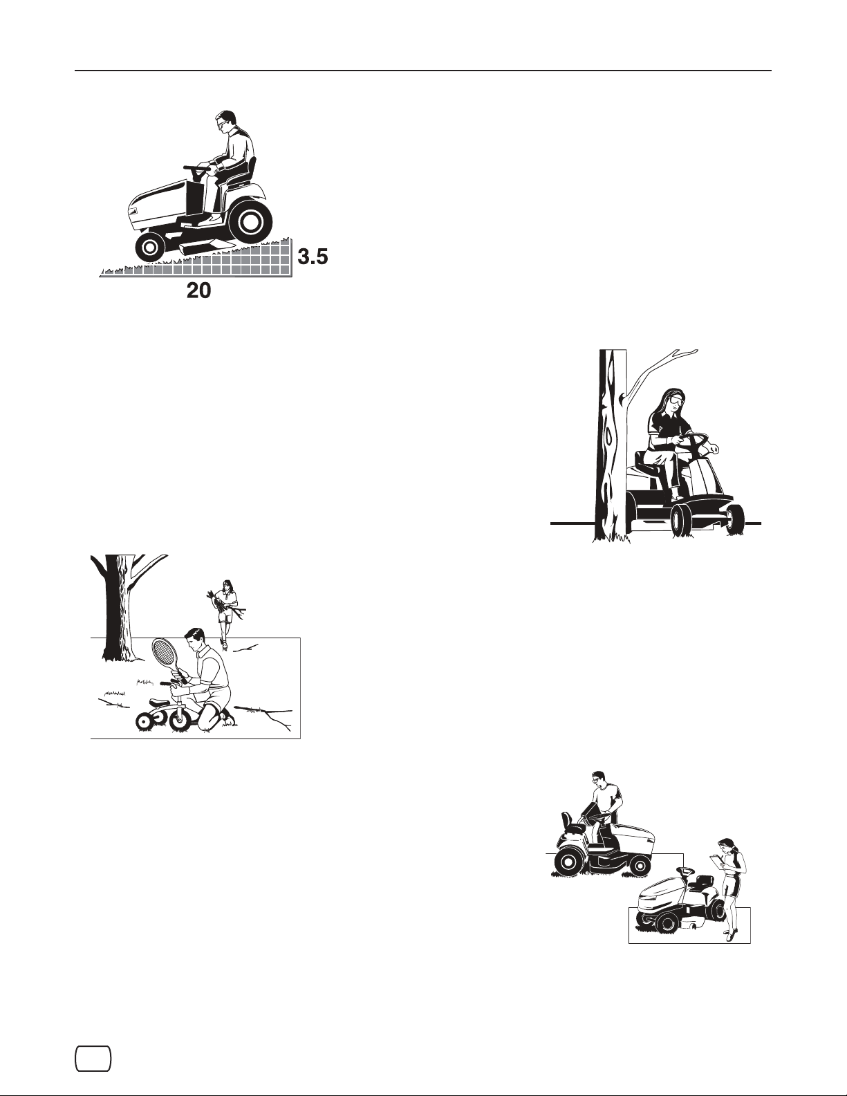
Children
Children
Tragic accidents can occur with children. Do not allow them any-
Tragic accidents can occur with children. Do not allow them
where near the area of operation. Children are often attracted
anywhere near the area of operation. Children are often at-
to the unit and mowing activity. Never assume that children will
tracted to the unit and mowing activity. Never assume that
remain where you last saw them. If there is a risk that children
children will remain where you last saw them. If there is a
may enter the area where you are mowing, have another respon-
risk that children may enter the area where you are mow-
sible adult watch them.
ing, have another responsible adult watch them.
DO NOT GIVE CHILDREN RIDES ON THIS UNIT! This
DO NOT GIVE CHILDREN RIDES ON THIS UNIT! This encour-
encourages them to come near the unit in the future while it
ages them to come near the unit in the future while it is running,
and they could be seriously hurt. They may then approach the
is running, and they could be seriously hurt. They may then
unit for a ride when you are not expecting it, and you may run
approach the unit for a ride when you are not expecting it,
over them.
and you may run over them.
Reverse
Reverse
Do not mow in reverse unless absolutely
Do not mow in reverse unless ab-
necessary. Always look down and
solutely necessary. Always look down
behind before and while traveling
and behind before and while
in reverse even with the mower
traveling in reverse even with
blades disengaged.
the mower blades disen-
gaged.
www.snapper.com4
Page 5
Not for
Reproduction
Operator Safety
en es fr
Slope Operation
You could be seriously injured or even killed if you use this unit on too steep
an incline. Using the unit on a slope that is too steep or where you don’t have
You could be seriously injured or even killed if you use this unit on too
adequate traction can cause you to lose control or roll over.
steep an incline. Using the unit on a slope that is too steep or where you
don’t have adequate traction can cause you to lose control or roll over.
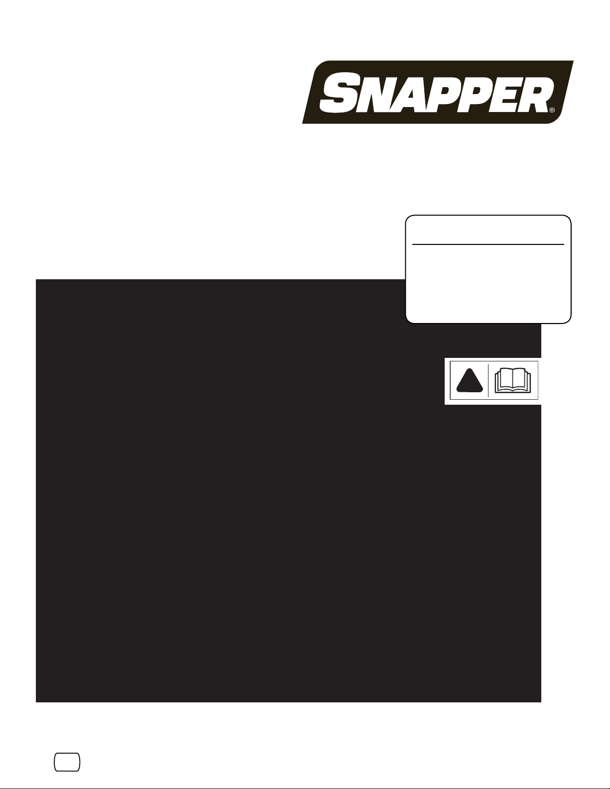
A good rule of thumb is to not operate on any slope you cannot back up (in
A good rule of thumb is to not operate on any slope you cannot back up
2-wheel drive mode). You should not operate on inclines with a slope greater
(in 2-wheel drive mode). You should not operate on inclines with a slope
than a 3.5 ft (1,5 m) rise over a 20.0 ft (6,0 m) length. Always drive up and
greater than a 3.5 ft (1,5 m) rise over a 20.0 ft (6,0 m) length. Always
down slopes: never cross the face.
drive up and down slopes: never cross the face.
Also note that the surface you are driving on can greatly impact stability and
Also note that the surface you are driving on can greatly impact stability
control. Wet grass or icy pavement can seriously affect your ability to control
and control. Wet grass or icy pavement can seriously affect your ability
the unit.
to control the unit.
If you feel unsure about operating the unit on an incline, don’t do it. It’s
If you feel unsure about operating the unit on an incline, don’t do it. It’s not
not worth the risk.
worth the risk.
Slope Operation
Moving Parts
Moving Parts
This equipment has many moving parts that can injure you or someone else. However,
This equipment has many moving parts that can injure you or someone else. How-
if you are seated in the seat properly, and follow all the rules in this book, the unit is
ever, if you are seated in the seat properly, and follow all the rules in this book, the
safe to operate.
unit is safe to operate.
The mower deck has spinning mower blades that can amputate hands and feet. Do
The mower deck has spinning mower blades that can amputate hands and feet.
not allow anyone near the equipment while it is running!
Do not allow anyone near the equipment while it is running!
To help you, the operator, use this equipment safely, it is equipped with an operator-
To help you, the operator, use this equipment safely, it is equipped with an operator
present safety system. Do NOT attempt to alter or bypass the system. See your
present safety system. Do NOT attempt to alter or bypass the system. See your dealer
dealer immediately if the system does not pass all the safety interlock system
immediately if the system does not pass all the safety interlock system tests found in
tests found in this manual.
this manual.
Thrown Objects
Thrown Objects
This unit has spinning mower blades. These blades can pick up and throw debris
This unit has spinning mower blades. These blades can pick up and throw debris
that could seriously injure a bystander. Be sure to clean up the area to be mowed
that could seriously injure a bystander. Be sure to clean up the area to be
BEFORE you start mowing.
mowed BEFORE you start mowing.
Do not operate this unit without the entire grass catcher or discharge guard (deflec-
Do not operate this unit without the entire grass catcher or discharge guard (de-
tor) in place.
flector) in place.
Also, do not allow anyone in the area while the unit is running! If someone does
Also, do not allow anyone in the area while the unit is running! If someone does enter
enter the area, shut the unit off immediately until they leave.
the area, shut the unit off immediately until they leave.
Fuel and Maintenance
Fuel and Maintenance
Gasoline is extremely flammable. Its vapors are also extremely flammable and
Gasoline is extremely flammable. Its vapors are also extremely flammable and can
can travel to distant ignition sources. Gasoline must only be used as a fuel, not
travel to distant ignition sources. Gasoline must only be used as a fuel, not as a sol-
as a solvent or cleaner. It should never be stored any place where its vapors
vent or cleaner. It should never be stored any place where its vapors can build up
can build up or travel to an ignition source like a pilot light. Fuel belongs in an
or travel to an ignition source like a pilot light. Fuel belongs in an approved, plastic,
approved, plastic, sealed gas can, or in the tractor fuel tank with the cap se-
sealed gas can, or in the tractor fuel tank with the cap securely closed. Spilled fuel
curely closed. Spilled fuel needs to be cleaned up immediately.
needs to be cleaned up immediately.
Proper maintenance is critical to the safety and performance of your unit. Be
Proper maintenance is critical to the safety and performance of your unit. Be sure
sure to perform the maintenance procedures listed in this manual, especially pe-
to perform the maintenance procedures listed in this manual, especially periodically
riodically testing the safety system.
testing the safety system.
5
Page 6
Not for
Reproduction
Operator Safety
WARNING: This powerful cutting machine is capable of amputating hands and feet and can throw objects
!
that can cause injury and damage! Failure to comply with the following SAFETY instructions could result in
serious injury or death to the operator or other persons. The owner of the machine must understand these
instructions and must allow only persons who understand these instructions to operate machine. Each
person operating the machine must be of sound mind and body and must not be under the influence of any
substance, which might impair vision, dexterity or judgment.
WARNING
POISONOUS GAS HAZARD. Engine exhaust contains carbon
monoxide, a poisonous gas that could kill you in minutes. You
CANNOT see it, smell it, or taste it. Even if you do not smell
exhaust fumes, you could still be exposed to carbon monoxide gas. If you start to feel sick, dizzy, or weak while using this
product, shut it off and get to fresh air RIGHT AWAY. See a
doctor. You may have carbon monoxide poisoning.
• Operate this product ONLY outside far away from windows, doors and
vents to reduce the risk of carbon monoxide gas from accumulating and
potentially being drawn towards occupied spaces.
• Install battery-operated carbon monoxide alarms or plug-in carbon
monoxide alarms with battery back-up according to the manufacturer’s
instructions. Smoke alarms cannot detect carbon monoxide gas.
• DO NOT run this product inside homes, garages, basements, crawlspaces, sheds, or other partially-enclosed spaces even if using fans or opening doors and windows for ventilation. Carbon monoxide can quickly
build up in these spaces and can linger for hours, even after this product
has shut off.
• ALWAYS place this product downwind and point the engine exhaust
away from occupied spaces.
Protection for Children
Tragic accidents can occur if the operator is not alert to the
presence of children. Children are often attracted to the
machine and the mowing activity. Children who have been
given rides in the past may suddenly appear in the mowing
area for another ride and be run over or backed over by the
machine. Never assume that children will remain where you
last saw them.
1. KEEP children out of the mowing area and under the
watchful care of a responsible adult other than the
operator.
2. DO NOT allow children in yard when machine is
operated (even with the blade OFF).
3. DO NOT allow children or others to ride on machine,
attachments or towed equipment (even with the blades
OFF). They may fall and be seriously injured.
4. DO NOT allow pre-teenage children to operate machine.
5. ALLOW only responsible adults & teenagers with mature
judgment under close adult supervision to operate
machine.
6. DO NOT operate blades in reverse unless absolutely
necessary. STOP BLADES. LOOK and SEE behind and
down for children, pets and hazards before and while
backing.
7. USE EXTRA CARE when approaching blind corners,
shrubs, trees, or other objects that may obscure vision.
Protection Against Tip-Overs/Roll-Overs
Slopes are a major factor related to loss-of-control and tipover/roll-over accidents, which can result in severe injury
or death. All slopes require extra CAUTION. If you cannot
back up the slope or if you feel uneasy on the slope, DO
NOT mow it. Use extra care with grass catchers or other
attachments; these affect the handling and the stability of
the machine.
1. DO NOT operate machine on slopes exceeding 10
degrees (18% grade).
2. Turn blades OFF when traveling uphill. Use a slow
speed and avoid sudden or sharp turns.
3. DO NOT operate machine back and forth across face of
slopes. Operate up and down. Practice on slopes with
blades off.
4. AVOID starting, stopping or turning on slopes. If
machine stops going uphill or tires lose traction, turn
blades OFF and back slowly straight down the slope.
5. STAY ALERT for holes and other hidden hazards. Tall
grass can hide obstacles. Keep away from ditches,
washouts, culverts, fences and protruding objects.
6. KEEP A SAFE DISTANCE (at least two mower widths)
away from edge of ditches and other drop offs. The
machine could turn over if an edge caves in.
7. Always begin forward motion slowly and with caution.
8. DO NOT begin forward motion while the machine is rolling backwards. A rearward tip-over may result.
9. Use weights or a weighted load carrier in accordance
with instructions supplied with a grass catcher or other
attachments. DO NOT operate machine on slopes
exceeding 10 degrees (18% grade) when equipped with
grass catcher or other attachments.
10. DO NOT put your foot on the ground to try to stabilize
the machine.
11. DO NOT operate machine on wet grass. Reduced traction could cause sliding.
12. Choose a low enough speed setting so that you will not
have to stop or shift on a slope. Tires may lose traction
on slopes even though the brakes are functioning properly.
13. DO NOT operate machine under any condition where
traction, steering or stability is doubtful.
14. Always keep the machine in gear when going down
slopes. DO NOT shift to neutral (or actuate hydro roll
release) and coast downhill.
15. Machine stability is tested in accordance with the applicable ANSI B71 standard using an operator weight of
200 lbs. To minimize the risk of a tip-over or roll-over,
operators weighing more than 200 lbs. should further
limit the ground speed and the degree of slope to be
mowed.
www.snapper.com6
Page 7

Not for
Reproduction
Operator Safety
en es fr
Preparation
1. Read, understand, and follow instructions and warnings
in this manual and on the machine, engine and attachments. Know the controls and the proper use of the
machine before starting.
2. Only mature, responsible persons shall operate the
machine and only after proper instruction.
3. Data indicates that operators age 60 and above, are
involved in a large percentage of mower-related injuries.
These operators should evaluate their ability to operate
the mower safely enough to protect themselves and others from serious injury.
4. Handle fuel with extra care. Fuels are flammable and
vapors are explosive. Use only an approved fuel container. DO NOT remove fuel cap or add fuel with engine
running. Add fuel outdoors only with engine stopped and
cool. Clean spilled fuel from machine. DO NOT smoke.
5. Practice operation of machine with BLADES OFF to
learn controls and develop skills.
6. Check the area to be mowed and remove all objects
such as toys, wire, rocks, limbs and other objects that
could cause injury if thrown by blade or interfere with
mowing.
7. Keep people and pets out of mowing area. Immediately
STOP blades, STOP engine, and STOP machine if anyone enters the area.
8. Check shields, deflectors, switches, blade controls and
other safety devices frequently for proper operation and
location.
9. Make sure all safety decals are clearly legible. Replace if
damaged.
10. Protect yourself when mowing and wear safety glasses,
a dust mask, hearing protection, long pants and substantial footwear.
11. Know how to STOP blades and engine quickly in preparation for emergencies.
12. Use extra care when loading or unloading the machine
into a trailer or truck.
13. Check grass catcher components frequently for signs of
wear or deterioration and replace as needed to prevent
injury from thrown objects going through weak or worn
spots.
Safe Handling of Gasoline
To avoid personal injury or property damage, use extreme
care in handling gasoline. Gasoline is extremely flammable
and the vapors are explosive.
1. Extinguish all cigarettes, cigars, pipes and other sources
of ignition.
2. Use only an approved fuel container.
3. DO NOT remove fuel cap or add fuel with the engine
running. Allow the engine to cool before refueling.
4. DO NOT refuel the machine indoors.
5. DO NOT store the machine or fuel container inside
where there is an open flame, spark or pilot light such as
on a water heater or other appliances.
6. DO NOT fill fuel containers inside a vehicle or on a truck
or trailer bed with a plastic liner. Always place the containers on the ground away from the vehicle before filling.
7. Remove gas-powered equipment from the vehicle or
trailer and refuel it on the ground. If this is not possible,
then refuel equipment using a portable container, rather
than a gasoline dispenser nozzle.
8. DO NOT start gas powered equipment in enclosed
vehicles or trailers.
9. Keep the nozzle in contact with the rim of the fuel tank or
container opening at all times until fueling is complete.
DO NOT use a nozzle lock-open device
10. If fuel is spilled on clothing, change clothing immediately.
11. Never overfill a fuel tank. Replace fuel cap and tighten
securely.
Operation
1. Mount and dismount machine from left side. Keep clear
of discharge opening at all times.
2. Start engine from operator’s seat, if possible. Make sure
blades are OFF and parking brake is set.
3. DO NOT leave machine with engine running. STOP
engine, STOP blades, SET brake, and remove key
before leaving operators position of any reason.
4. DO NOT operate machine unless properly seated with
feet on feet rests or pedal(s).
5. STOP BLADES and ENGINE and make sure blades
have stopped before removing grass catcher or unclogging mower to prevent loss of fingers or hand.
6. Blades must be OFF except when cutting grass. Set
blades in highest position when mowing over rough
ground.
7. Keep hands and feet away from rotating blades underneath deck. DO NOT place foot on ground while
BLADES are ON or machine is in motion.
8. DO NOT operate machine without entire grass catcher
or guards in place and working. DO NOT point discharge at people, passing cars, windows or doors.
9. Slow down before turning.
10. Watch out for traffic when near or crossing roadways.
11. STOP engine immediately after striking an obstruction.
Inspect machine and repair damage before resuming
operation.
12. Operate machine only in daylight or with good artificial
light.
13. Exercise CAUTION when pulling loads. Limit loads to
those you can safely control and attach loads to hitch
plate as specified with attachment instructions.
14. On slopes, the weight of the towed equipment may
cause loss of traction and loss of control. When towing,
travel slowly and allow extra distance to stop.
15. DO NOT operate engine in enclosed areas. Engine
exhaust gases contain carbon monoxide, a deadly poison.
16. DO NOT discharge material against a wall or obstruction. Material may ricochet back towards the operator.
17. Only use accessories approved by the manufacturer.
See manufacturer’s instructions for proper operation and
installation of accessories.
7
Page 8

Not for
Reproduction
Operator Safety
Towing
1. Tow only with a machine that has a hitch designed for
towing. DO NOT attach towed equipment except at the
hitch point.
2. Refer to “Towing Implements” in the Operation section
regarding weight limits for towed equipment and towing
on slopes.
3. DO NOT allow children or others on towed equipment.
4. On slopes, the weight of the towed equipment may
cause loss of traction and loss of control. Use caution
while operating on slopes.
5. Travel slowly and allow extra distance to stop.
Maintenance
1. DO NOT store machine or fuel container inside where
fumes may reach an open flame, spark or pilot light such
as in a water heater, furnace, clothes dryer or other gas
appliance. Allow engine to cool before storing machine
in an enclosure. Store fuel container out of the reach of
children in a well ventilated, unoccupied building.
2. Keep engine and machine free of grass, leaves or
excess grease to reduce fire hazard and engine overheating.
3. When draining fuel tank, drain fuel into an approved container outdoors and away from open flame.
4. Check brakes frequently; adjust, repair or replace as
needed.
5. Keep all bolts, nuts and screws properly tight. Check
that all cotter pins are in proper position.
6. Always provide adequate ventilation when running
engine. Exhaust gases contain carbon monoxide, an
odorless and deadly poison.
7. Disconnect negative (black) cable from battery before
performing maintenance or service. Cranking engine
could cause injury.
8. DO NOT work under machine without safety blocks.
9. DO NOT stand unit on end.
10. Service engine and make adjustments only when engine
is stopped. Remove spark plug wire(s) from spark
plug(s) and secure wire(s) away from spark plug(s).
11. DO NOT change engine governor speed settings or
overspeed engine.
12. Lubricate machine at intervals specified in manual to
prevent controls from binding.
13. Mower blades are sharp and can cut. Wrap the blades
or wear heavy leather gloves and use CAUTION when
handling them.
14. DO NOT test for spark by grounding spark plug next
to spark plug hole; spark plug could ignite gas exiting
engine.
15. Have machine serviced by an authorized dealer at least
once a year and have the dealer install any new safety
devices.
16. Maintain or replace safety and instruction labels as necessary.
17. Use only factory authorized replacement parts or equivalent when making repairs.
!
It is a violation of California Public Resource Code, Section
4442, to use or operate the engine on any forest-covered,
brush-covered, or grass-covered land unless the exhaust
system is equipped with a spark arrester, as defined
in Section 4442, maintained in effective working order.
Other states or federal jurisdictions may have similar laws.
Contact the original equipment manufacturer, retailer, or
dealer to obtain a spark arrester designed for the exhaust
system installed on this engine.
WARNING
!
!
Battery posts, terminals and related accessories contain
lead and lead compounds, chemicals known to the State of
California to cause cancer and birth defects or other reproductive harm. Wash hands after handling.
!
Engine exhaust, some of its constituents, and certain
vehicle components contain or emit chemicals known to the
State of California to cause cancer or other reproductive
harm.
WARNING
WARNING
www.snapper.com8
!
!
Page 9
Not for
Reproduction
en es fr
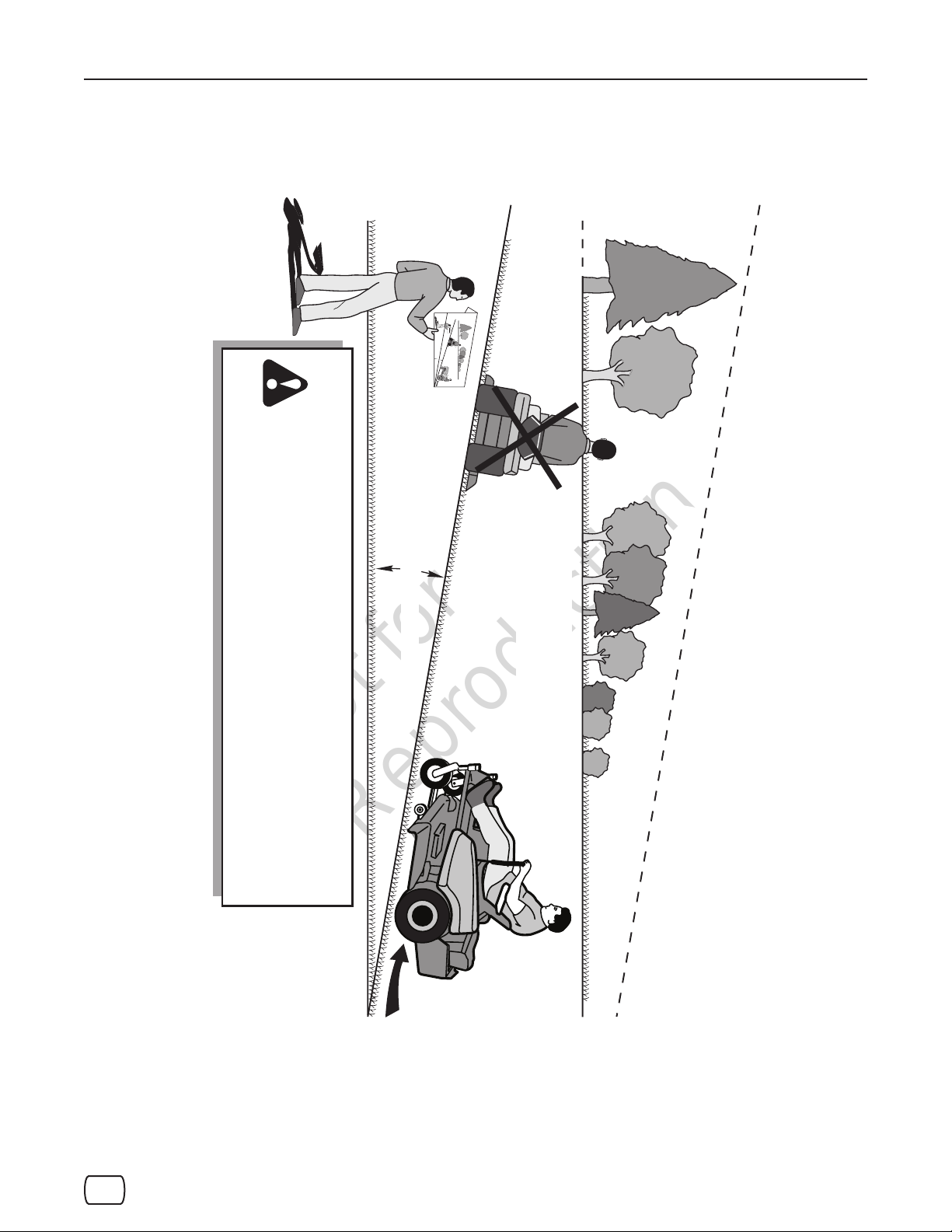
4. Compare the angle of the fold with the slope of the hill.
SUGGESTED GUIDE FOR SIGHTING SLOPES FOR SAFE OPERATION
4. Compare the angle of the fold with the slope of the hill.
3. Sight across the fold in the direction of hill slope you want to measure.
1. Fold this page along dotted line indicated above.
2. Hold page before you so that its left edge is vertically parallel to a tree
trunk or other upright structure.
other upright structure.
WARNING: To avoid serious injury, operate your unit up and
down the face of slopes, never across the face. Do not oper-
ate on slopes greater than 10 degrees. Make turns gradually
to prevent tipping or loss of control. Exercise extreme caution
when changing direction on slopes. Braking may be aected by
attachments. Reduce speed on slopes.
prevent tipping or loss of control. Exercise extreme caution
when changing direction on slopes. Braking may be affected by
attachments. Reduce speed on slopes.
WARNING: To avoid serious injury, operate your unit up and
down the face of slopes, never across the face. Do not operate
on slopes greater than 10 degrees. Make turns gradually to
10 DEGREES MAX.
10 DEGREES MAX.
1. Fold this page along dotted line indicated above.
2. Hold page before you so that its left edge is vertically parallel to a tree trunk or
3. Sight across the fold in the direction of hill slope you want to measure.
Operator Safety
ONLY RIDE UP AND DOWN HILL,
NOT ACROSS HILL
ONLY RIDE UP AND DOWN HILL,
NOT ACROSS HILL
THIS IS A 10 DEGREE SLOPE
THIS IS A 10 DEGREE SLOPE
F
FOLD ALONG DOTTED LINE
O
L
D
A
LON
SUGGESTED GUIDE FOR SIGHTING SLOPES FOR SAFE OPERATION
G
D
OT
TED LI
N
E
9
Page 10
Not for
Reproduction
Operator Safety
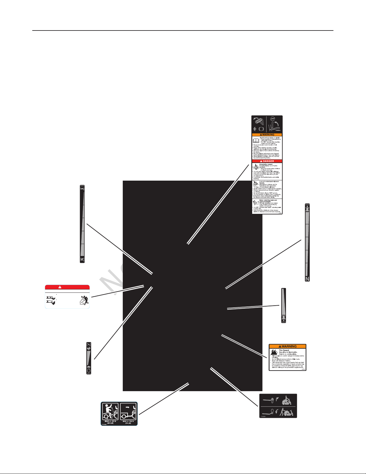
Safety and Instructional Decals
All DANGER, WARNING, CAUTION and instructional
messages on your rider and mower should be carefully
read and obeyed. Personal bodily injury can result when
these instructions are not followed. The information is for
your safety and it is important! The safety decals below are
on your rider and mower.
If any of these decals are lost or damaged, replace them at
once. See an authorized dealer for replacements.
These labels are easily applied and will act as a constant
visual reminder to you, and others who may use the equipment, to follow the safety instructions necessary for safe,
effective operation.
Brake/Blade,
Warning/Danger
Cutting Height
DANGER
Amputation and thrown objects hazard
Keep hands and feet
away from deck.
Do not operate mower
unless discharge chute
or entire grass catcher
is in its proper place.
Warning - Deflector
(2 - one on each side of deck)
7101665
Engine Speed
Weight Limitation
Forward
Speed
Reverse
Speed
Warning -
Fire Hazard
Transmission
Release
www.snapper.com10
Page 11
Not for
Reproduction
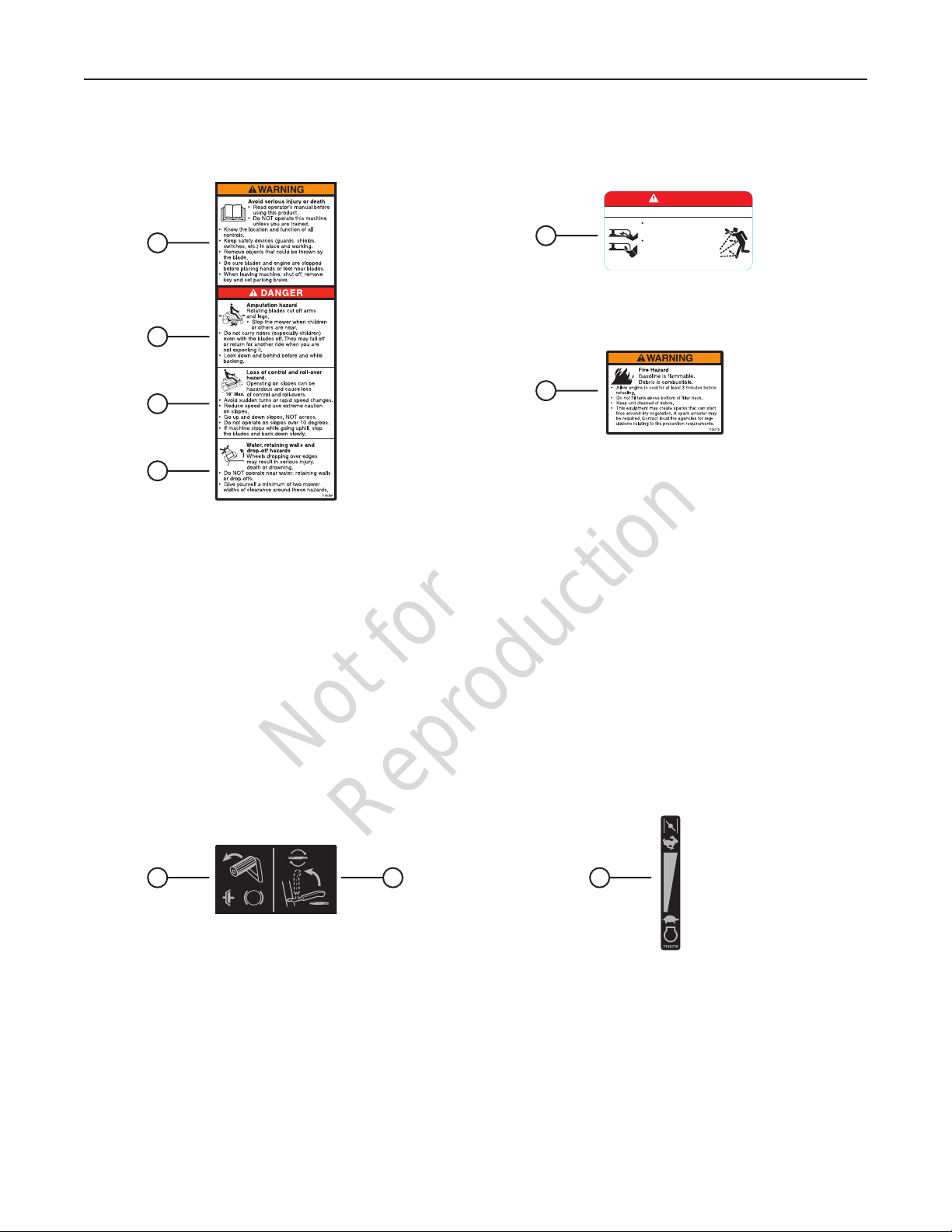
Explanation of Safety Decals
A
B
Operator Safety
DANGER
Amputation and thrown objects hazard
Keep hands and feet
E
away from deck.
Do not operate mower
unless discharge chute
or entire grass catcher
is in its proper place.
7101665
C
D
A. Read the operator’s manual before using the product.
B. Do not mow when others are in the area, especially
children.
C. Use extreme caution when operating on slopes.
D. Do not operate near walls and other drop-offs.
Explanation of Instructional Decals
F
E. Keep hands and feet away / Do not operate without
discharge chute or grass catcher in place.
F. Use extreme caution when refueling.
A B
A. Clutch/Brake. Shows operation of clutch (manual drive
models) and brake. Refer to Operation section.
B. Blade Engage. Shows operation of blade engage lever.
Refer to Operation section.
C
C. Engine Speed Control. Shows operation of engine speed
control and choke control (on applicable models). Refer to
Operation section.
11
Page 12
Not for
Reproduction
Operator Safety
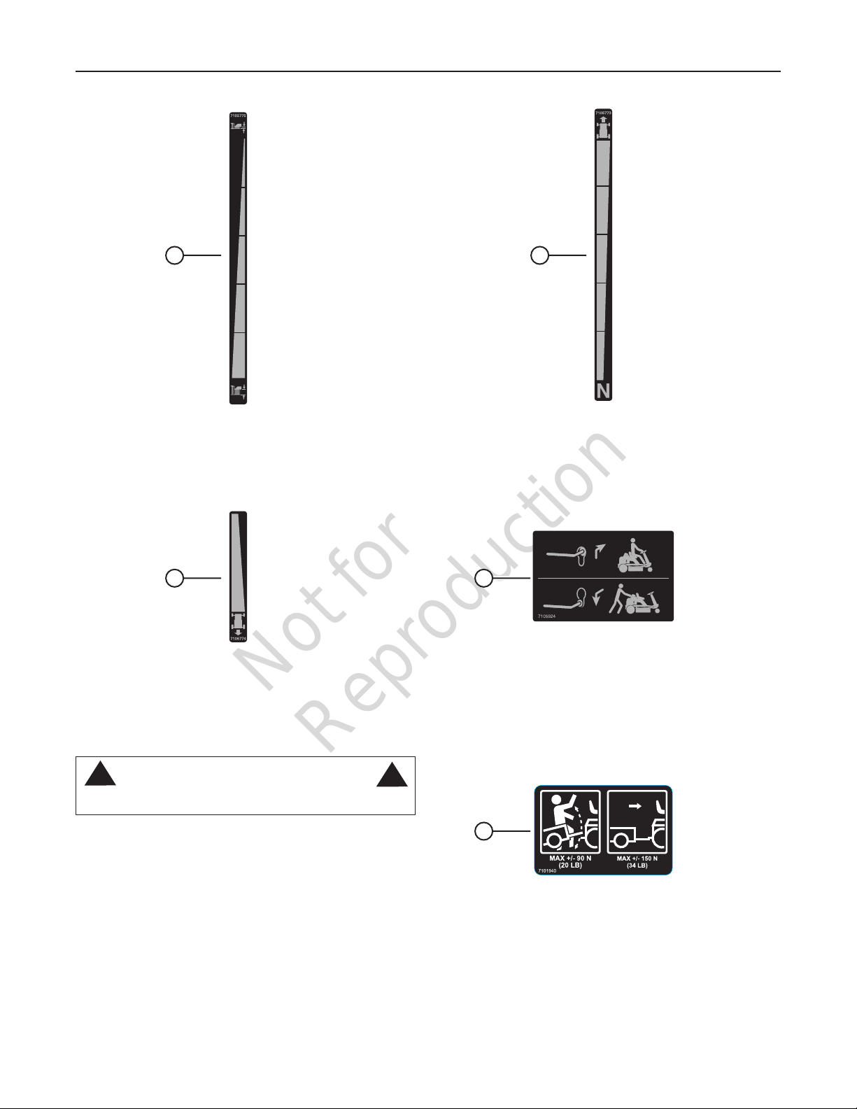
D E
D. Cutting Height. Shows position of cutting height adjust
lever. Refer to Operation section.
F G
F. Reverse Speed. Shows reverse speed operation (manual
drive models). Refer to Operation section.
!
Do not mow in reverse unless absolutely necessary.
WARNING
!
E. Forward Speed. Shows forward speed operation (manual
drive models). Refer to Operation section.
G. Transmission Release. Shows operation of transmission
release lever (hydro drive models). Refer to Operation section.
H
H. Weight Limitation. Notes limits of weight when towing
implements. Refer to Operation section.
www.snapper.com12
Page 13

Not for
Reproduction
en es fr
IMPORTANT
The figures and illustrations in this manual are provided
for reference only and may differ from your specific model.
Contact your dealer if you have questions.
Features and Controls
N
M
L
K
J
A
B
C
D
E
F
G
Features and Controls
A. Operator Seat
B. Steering Wheel - controls direction of unit
C. Engine Speed Control (hidden from view) -
controls engine speed
D. Cutting Height Adjust Lever - adjusts cutting
height
E. Parking Brake Latch (hidden from view) - locks
brake
F. Blade Control - engages mower blade
G. Clutch/Brake Pedal - engages clutch (manual
drive models) and brake
H. Headlight (not shown; select models)
I. Mulching Cover
H
I
P
J. Ignition Switch - starts engine
K. Transmission Release Lever (hidden from view;
hydro drive models) - releases transmission so
unit can roll freely
L. Reverse Mowing Switch - temporarily allows
mower blade to operate with transmission in
reverse.
M. Transmission Shift Lever (manual drive models)
- selects transmission speed and direction
N. Fuel Tank
O. Forward Ground Speed Pedal (hydro drive
models) - controls forward ground speed
P. Reverse Ground Speed Pedal (hydro drive
models) - controls reverse ground speed
O
13
Page 14

Not for
Reproduction
Operation
Before Starting
Make the following checks and perform the service required
before each start-up:
1. Check the tire pressure; add or release air as needed. Refer to “How To Check Tire Pressure” in the
Maintenance section.
2. Check guards, deflectors and covers to make sure all
are in place and securely tightened.
3. Check engine oil and add oil as needed. Refer to “How
To Check/Add Oil”.
4. Add fuel to the fuel tank as needed. Refer to “How to
Add Fuel”.
5. Adjust the operator seat as needed to the most comfortable position. Refer to “How To Adjust The Operator
Seat”.
6. Check all operator controls to ensure they operate freely
without binding.
7. Perform the Safety Interlock System Checks. Refer to
“Safety Interlock System Checks”.
Safety Interlock System Checks
!
DO NOT operate machine if any safety interlock or safety
device is not in place and functioning properly. Contact
your dealer immediately for assistance. DO NOT attempt to
defeat, modify or remove any safety device.
Engine must not start if:
1. The Clutch/Brake Pedal is not fully depressed OR,
2. The Blade Control is in the ON (engaged) position.
Engine should start if:
1. The operator is seated in the operator seat AND,
2. The Blade Control is in the OFF (disengaged) position
AND,
3. The Clutch/Brake Pedal is fully depressed.
Engine and blade must stop if:
1. The operator rises off of the operator seat OR,
2. The operator attempts to drive the unit in reverse with
the mower blade engaged and the reverse mowing
option function (RMO) not activated.
WARNING
!
* Below 40°F (4°C) the use of SAE 30 will result in hard starting.
** Above 80°F (27°C) the use of 10W-30 may cause increased oil
consumption. Check oil level more frequently.
How To Check/Add Oil
Before adding or checking the oil
• Place engine level.
• Clean the oil fill area of any debris.
1. Remove the dipstick (A, Figure 1) and wipe with a clean
cloth.
NOTE: On some models, the dipstick is accessible through
an opening behind the operator seat.
2. Insert and tighten the dipstick.
3. Remove the dipstick and check the oil level. It should be
at the top of the full indicator (B) on the dipstick.
4. If low, add oil slowly into the engine oil fill (C). Do not
overfill. After adding oil, wait one minute and then
recheck the oil level.
5. Replace and tighten the dipstick.
C
A
Oil Recommendations
We recommend the use of Briggs & Stratton Warranty
Certified oils for best performance. Other high-quality detergent oils are acceptable if classified for service SF,
SG, SH, SJ or higher. Do not use special additives.
Outdoor temperatures determine the proper oil viscosity for
the engine. Use the chart to select the best viscosity for the
outdoor temperature range expected.
A
B
Figure 1: Engine oil
www.snapper.com14
Page 15

Not for
Reproduction
Operation
en es fr
Fuel Recommendations
Fuel must meet these requirements:
• Clean, fresh, unleaded gasoline.
• A minimum of 87 octane/87 AKI (91 RON). High altitude
use, see below.
• Gasoline with up to 10% ethanol (gasohol) is acceptable.
NOTICE: Do not use unapproved gasolines, such as E15
and E85. Do not mix oil in gasoline or modify the engine to
run on alternate fuels. This will damage the engine components and void the engine warranty.
To protect the fuel system from gum formation, mix a fuel
stabilizer into the fuel. Refer to “Storage”. All fuel is not the
same. If starting or performance problems occur, change fuel
providers or change brands. This engine is certified to operate on gasoline. The emissions control system for this engine
is EM (Engine Modifications)
High Altitude
At altitudes over 5,000 feet (1524 meters), a minimum 85
octane/85 AKI (89 RON) gasoline is acceptable. To remain
emissions compliant, high altitude adjustment is required.
Operation without this adjustment will cause decreased performance, increased fuel consumption, and increased emissions. See a Briggs & Stratton Authorized Dealer for high
altitude adjustment information.
Operation of the engine at altitudes below 2,500 feet (762
meters) with the high altitude adjustment is not recommended.
A
B
Figure 2: Fuel cap
How To Adjust The Operator Seat
With the engine stopped:
1. Raise the operator seat.
2. Loosen the two adjusting knobs (A, Figure 3) and move
the seat to the desired position. After adjustment, tighten
the knobs securely.
3. Lower the operator seat.
How To Add Fuel
!
Fuel and its vapors are extremely flammable and explosive.
Fire or explosion can cause severe burns or death.
When Adding Fuel
• Turn engine off and let engine cool at least 5 minutes
before removing the fuel cap.
• Fill fuel tank outdoors or in well-ventilated area.
• Do not overfill fuel tank. To allow for expansion of the
fuel, do not fill above the bottom of the fuel tank neck.
• Keep fuel away from sparks, open flames, pilot lights,
heat, and other ignition sources.
• Check fuel lines, tank, cap, and fittings frequently for
cracks or leaks. Replace if necessary
• If fuel spills, wait until it evaporates before starting
engine.
1. Clean the fuel cap area of dirt and debris. Remove the
fuel cap (A, Figure 2).
2. Fill the fuel tank with fuel. To allow for expansion of the
fuel, do not fill above the bottom of the fuel tank neck
(B).
3. Reinstall the fuel cap.
WARNING
A
!
Figure 3: Operator seat adjustment
15
Page 16

Not for
Reproduction
Operation
How To Start The Engine
WARNING
POISONOUS GAS HAZARD. Engine exhaust contains carbon
monoxide, a poisonous gas that could kill you in minutes. You
CANNOT see it, smell it, or taste it. Even if you do not smell
exhaust fumes, you could still be exposed to carbon monoxide gas. If you start to feel sick, dizzy, or weak while using this
product, shut it off and get to fresh air RIGHT AWAY. See a
doctor. You may have carbon monoxide poisoning.
• Operate this product ONLY outside far away from windows, doors and
vents to reduce the risk of carbon monoxide gas from accumulating and
potentially being drawn towards occupied spaces.
• Install battery-operated carbon monoxide alarms or plug-in carbon
monoxide alarms with battery back-up according to the manufacturer’s
instructions. Smoke alarms cannot detect carbon monoxide gas.
• DO NOT run this product inside homes, garages, basements, crawlspac-
es, sheds, or other partially-enclosed spaces even if using fans or opening doors and windows for ventilation. Carbon monoxide can quickly
build up in these spaces and can linger for hours, even after this product
has shut off.
• ALWAYS place this product downwind and point the engine exhaust
away from occupied spaces.
1. Sit squarely in the operator seat.
2. Manual Drive Models - Move the transmission shift lever
to the Neutral (‘N’) position. Refer to “How To Engage
The Transmission”.
!
DO NOT start the engine with the transmission shift lever in
a drive position. Follow starting instructions carefully.
WARNING
!
NOTE: If after 5 seconds of cranking the engine does not
start, release the key, make sure the Clutch/Brake Pedal is
fully depressed, and attempt starting again after waiting for
approximately 20 seconds.
7. After the engine starts, move the engine speed control to
the FAST position (if equipped with choke) and allow a
brief warm-up until engine runs smooth.
NOTE: Always operate with the engine speed control in the
FAST position.
NOTE: The headlight (featured on select models) is
operational any time the ignition switch is in the RUN or
START position.
A
Figure 5: Clutch/brake pedal
3. Make sure the Blade Control (A, Figure 4) is in the OFF
position.
A
Figure 4: Blade control
4. Fully depress the Clutch/Brake Pedal (A, Figure 5).
5. Move the engine speed control (A, Figure 6) to the
FAST position (or CHOKE position, if equipped).
NOTE: The CHOKE position is not required when starting a
warm engine.
6. Insert the ignition key (A, Figure 7) into the ignition
switch. Turn the key to the START position until the
engine starts.
NOTE: When the ignition key is turned to START, the engine
will turn over, but will not start unless the Clutch/Brake pedal
is fully depressed and the Blade Control is in the OFF position.
A
Figure 6: Engine speed control
A
Figure 7: Ignition key
www.snapper.com16
Page 17

Not for
Reproduction
en es fr
Operation
How To Engage The Mower Blade
1. Start the engine.
2. Move the blade control (A, Figure 8) to the ON position.
A
Figure 8: Engaging the blade control
How To Engage The Transmission
Manual Drive Models:
1. Start the engine.
2. To move forward:
• Depress the clutch/brake pedal (A, Figure 9).
• Move the transmission shift lever (A, Figure 10) from
the Neutral (‘N’) position (B) into the first forward speed
notch (C).
• Release the clutch/brake pedal to begin forward
motion.
• During forward motion, the transmission shift lever may
be placed in any desired forward speed (D) without
depressing the clutch/brake pedal.
3. To move backward:
• Depress the clutch/brake pedal (A, Figure 9).
• Move the transmission shift lever (A, Figure 10) from
the Neutral (‘N’) position (B) into the reverse speed slot
(E).
• During reverse motion, the transmission shift lever
may be placed in any desired reverse speed without
depressing the clutch/brake pedal.
NOTICE: If the transmission is moved into reverse while the
mower blade is engaged, the engine will shut off. If mowing
in reverse is necessary, refer to “Reverse Mowing Option
(RMO)”.
!
LOOK and SEE behind and down for children, pets and
hazards before and while backing.
A
Figure 9: Clutch/brake pedal
E
Figure 10: Transmission shift lever (manual drive models)
WARNING
A
B
C
!
D
Hydro Drive Models:
1. Start the engine.
2. Make sure the parking brake is released. Refer to “How
To Set The Parking Brake”.
3. To move forward:
• Slowly depress the forward ground speed pedal (A,
Figure 11) to begin forward motion. Increase ground
speed by further depressing the pedal.
4. To move backward:
• Slowly depress the reverse ground speed pedal (B,
Figure 11) to begin reverse motion. Increase ground
speed by further depressing the pedal.
NOTE: For best cutting results, choose a slow forward
speed with the engine speed control in the FAST position.
This combination will allow the mower blade to lift the grass
while cutting smoothly and evenly.
A
B
Figure 11: Ground speed pedals (hydro drive models)
17
Page 18

Not for
Reproduction
Operation
!
DO NOT leave the machine with the engine running. STOP
Blade. STOP engine. Shift to neutral and engage parking
brake. Remove key.
WARNING
!
How To Stop The Engine,
Transmission And Mower Blade
Engine
1. Stop the engine by turning the ignition key (A, Figure 12)
to the OFF position.
2. Remove the key.
A
Figure 12: Turning ignition key to OFF
A
Figure 14: Ground speed pedals (hydro drive models)
Mower Blade
1. Stop the mower blade by moving the blade control (A,
Figure 15) to the OFF position.
A
Transmission
Manual Drive Models:
1. Stop motion of the unit by fully depressing the clutch/
brake pedal (A, Figure 13) to disengage the clutch and
apply the brake.
2. Return the transmission shift lever to the Neutral (‘N’)
position. Refer to “How To Engage The Transmission”.
A
Figure 13: Clutch/brake pedal
Hydro Drive Models:
1. Stop motion of the unit by fully releasing the ground
speed pedals (A, Figure 14). Additional braking can be
achieved by depressing the brake pedal (A, Figure 13).
Figure 15: Blade control
!
Once blade is disengaged, it should come to a complete
stop in 5 seconds or less. If the blade continues to rotate
after 5 seconds, the blade brake must be adjusted. Return
machine to an authorized dealer for adjustment. DO NOT
CONTINUE to operate machine until blade brake is adjusted and functioning properly.
WARNING
!
www.snapper.com18
Page 19

Not for
Reproduction
Operation
How To Set The Parking Brake
1. Fully depress the clutch/brake pedal (A, Figure 16).
2. Slide the parking brake (B) up and hold while releasing
the clutch/brake pedal. The parking brake is now set.
3. To release the parking brake, fully depress the clutch/
brake pedal. The parking brake will release automatically.
!
DO NOT park the machine on slopes.
A
WARNING
B
Reverse Mowing Option (RMO)
!
Mowing in reverse can be hazardous to bystanders. Tragic
accidents can occur if the operator is not alert to the presence of children. Never activate RMO if children are present. Children are often attracted to the unit and the mowing
activity.
!
1. Engage the mower blade. Refer to “How To Engage The
Mower Blade”.
2. Insert the supplied key (A, Figure 18) into the RMO
switch (B), and turn the key to activate the RMO function. The LED light (C) indicates that the RMO function is
now activated.
3. Engage the transmission in reverse. Refer to “How To
Engage The Transmission”.
4. The RMO function is deactivated when the mower blade
is disengaged.
WARNING
A
!
Figure 16: Setting the parking brake
How To Adjust The Cutting Height
1. Raise or lower the cutting height adjust lever (A, Figure
17) into the desired height of cut notch.
A
C
B
Figure 18: Reverse mowing switch
How To Install The Discharge
Deflector
!
DO NOT attempt any adjustments, maintenance, service or
repairs with the engine running. STOP engine. STOP blade.
Engage parking brake. Remove key. Remove spark plug
wire from spark plug and secure away from plug. Engine
and components are HOT. Avoid serious burns, allow all
parts to cool before working on machine.
1. Remove the wing nut and washer (A, Figure 19) securing the bottom edge of the mulching cover (B) to the
mower deck.
WARNING
!
Figure 17: Cutting height adjustment
19
Page 20

Not for
Reproduction
Operation
!
The mulching cover must remain on the machine at all
times. Do not remove.
2. Raise the mulching cover. Replace the washer and
wing nut onto the retaining bolt in the deck, tightening
securely.
3. Install the discharge deflector (A, Figure 20) to the
mower deck, making sure that the slots (B) in the deflector fit over the locking tabs (C) on the mulching cover
hinge bracket.
4. Lower the mulching cover.
5. To remove the discharge deflector:
• Raise the mulching cover.
• Lift and remove the discharge deflector from the
mower deck.
• Remove the wing nut and washer from the retaining
bolt in the deck.
• Lower the mulching cover, securing with the washer
and wing nut. Tighten securely.
WARNING
!
B
How To Push The Unit By Hand
Manual Drive Models:
1. Make sure the unit is parked on a flat, even surface.
2. Make sure the transmission shift lever is in the
Neutral (N) position. Refer to “How To Engage the
Transmission”.
3. Release the parking brake, if set. Refer to “How To Set
The Parking Brake”.
4. The unit can now be pushed by hand. Be sure to set the
parking brake after the unit is moved to the desired location.
Hydro Drive Models:
1. Make sure the unit is parked on a flat, even surface.
2. Release the parking brake, if set. Refer to “How To Set
The Parking Brake”.
3. Move the transmission release lever (located behind
the right rear tire) out and down into the locking slot (A,
Figure 21) to disengage the transmission.
4. The unit can now be pushed by hand.
5. After moving the unit to the desired location, move the
transmission release lever up and in (B) to engage the
transmission.
A
Figure 19: Raising the mulching cover
C
A
B
Figure 21: Transmission release lever
Towing Implements
B
The maximum horizontal drawbar force allowed is 34 lbs
(150 N) *. The maximum vertical drawbar force is 20 lbs (90
N) *.
* Approximate
Figure 20: Installing the discharge deflector
A
www.snapper.com20
Page 21

Not for
Reproduction
!
DO NOT attempt any adjustments, maintenance, service or
repairs with the engine running. STOP engine. STOP blade.
Engage parking brake. Remove key. Remove spark plug
wire from spark plug and secure away from plug. Engine
and components are HOT. Avoid serious burns, allow all
parts to cool before working on machine.
WARNING
!
Maintanance Chart
Maintenance
Emissions Control
Maintenance, replacement, or repair of the emissions control
devices and systems may be performed by any non-road
engine repair establishment or individual. However, to obtain
“no charge” emissions control service, the work must be
performed by a factory authorized dealer. See the Emissions
Warranty.
RIDER
Every 8 Hours or Daily
Check safety interlock system
Clean debris off rider
Clean debris from engine area
Every 25 Hours or Annually *
Check tire pressure
Check mower blade stopping time
Check rider for loose hardware
Every 50 Hours or Annually *
Clean battery and cables
Check brakes
See Dealer Annually to
Lubricate rider
Check mower drive belts
Check mower blades **
* Whichever comes first
** Check blades more often in regions with sandy soils
or high dust conditions.
ENGINE
First 5 Hours
Change engine oil
Every 8 Hours or Daily
Check engine oil level
Every 25 Hours or Annually *
Clean engine air filter and pre-cleaner **
Every 50 Hours or Annually *
Change engine oil
Replace oil filter
Annually
Replace air filter
Replace pre-cleaner
See Dealer Annually to
Inspect muffler and spark arrester
Replace spark plug
Replace fuel filter
Clean engine air cooling system
* Whichever comes first
** Clean more often in dusty conditions or when
airborne debris is present.
21
Page 22

Not for
Reproduction
Maintenance
!
DO NOT attempt any adjustments, maintenance, service or
repairs with the engine running. STOP engine. STOP blade.
Engage parking brake. Remove key. Remove spark plug
wire from spark plug and secure away from plug. Engine
and components are HOT. Avoid serious burns, allow all
parts to cool before working on machine.
WARNING
Engine Maintenance
How To Change The Engine Oil
Used oil is a hazardous waste product and must be disposed
of properly. Do not discard with household waste. Check with
your local authorities, service center, or dealer for safe disposal/recycling facilities.
1. Place bricks or wooden blocks under the front wheels to
lower the rear of the engine.
2. Loosen or remove the oil fill cap on the engine.
3. Place a 2 quart minimum capacity container under the
end of the oil drain (Figure 22).
4. Remove or open the oil drain plug (A or B, Figure 22),
depending upon the type of oil drain plug the engine is
equipped with.
NOTE: Location of oil drain may vary according to model.
!
How To Change The Oil Filter (if
equipped)
Some models are equipped with oil filter. For replacement
intervals, see the Maintenance chart.
1. Drain the oil from the engine. Refer to “How To Change
The Engine Oil”.
2. Remove the oil filter (A, Figure 23) and dispose of
properly.
NOTE: Location of oil filter may vary according to model.
3. Before you install the new oil filter, lightly lubricate the oil
filter gasket with fresh, clean oil.
4. Install the oil filter by hand until the gasket contacts the
oil filter adapter, then tighten the oil filter 1/2 to 3/4 turns.
5. Add oil. Refer to “How to Check/Add Oil” in the
Operation section.
6. Start and run the engine. As the engine warms up, check
for oil leaks.
7. Stop the engine and check the oil level. It should be at
the top of the full indicator on the dipstick.
A
B
Figure 22: Oil drain plugs
5. After all the oil has drained, replace or close the drain
plug, and wipe up any oil that may have spilled. Dispose
of used oil properly.
6. Fill the engine with new oil. Refer to “How To Check/
Add Oil” in the Operation Section.
A
Figure 23: Oil filter
www.snapper.com22
Page 23

Not for
Reproduction
en es fr
!
DO NOT attempt any adjustments, maintenance, service or
repairs with the engine running. STOP engine. STOP blade.
Engage parking brake. Remove key. Remove spark plug
wire from spark plug and secure away from plug. Engine
and components are HOT. Avoid serious burns, allow all
parts to cool before working on machine.
WARNING
!
How To Service The Air Filter
!
Fuel and its vapors are extremely flammable and explosive.
Fire or explosion can cause severe burns or death.
• Never start or run the engine with the air cleaner assembly (if equipped) or the air filter (if equipped) removed.
WARNING
!
Maintenance
Flat Air Filter
1. Pull up on the cover handle (A, Figure 25). Rotate the
cover handle toward the engine and then remove the
cover (B).
2. Remove the pre-cleaner (C), if equipped, and the filter
(D).
3. To loosen debris, gently tap the filter on a hard surface.
If the filter is excessively dirty, replace with a new filter.
4. Wash the pre-cleaner in liquid detergent and water.
Then allow it to thoroughly air dry. Do not oil the precleaner.
5. Assemble the dry pre-cleaner and the filter into the
engine base (E).
6. Align the tabs (F) on the cover with the slots (G) in the
blower housing. Rotate the cover handle back and push
down to lock in place.
NOTICE: Do not use pressurized air or solvents to clean the
filter. Pressurized air can damage the filter and solvents will
dissolve the filter.
Oval Air Filter
1. Remove the fastener (A, Figure 24) and the air filter
cover (B).
2. Remove the pre-cleaner (C), if equipped, and the filter
(D).
3. To loosen debris, gently tap the filter on a hard surface.
If the filter is excessively dirty, replace with a new filter.
4. Wash the pre-cleaner in liquid detergent and water.
Then allow it to thoroughly air dry. Do not oil the precleaner.
5. Assemble the dry pre-cleaner to the filter.
6. Install the filter and pre-cleaner into the base (E). Make
sure filter fits securely in the base.
7. Install air filter cover and secure with fastener. Make
sure the fastener is tight.
A
B
D
A
E
G
C
Figure 25: Air filter (flat)
Cylindrical Cartridge Air Filter
1. Remove the fasteners (A, Figure 26) and the air filter
cover (B).
2. To remove the filter (C), lift the end of the filter and then
pull the filter off the intake (D).
3. Remove the pre-cleaner (E), if equipped, from the filter.
4. To loosen debris, gently tap the filter on a hard surface.
If the filter is excessively dirty, replace with a new filter.
5. Wash the pre-cleaner in liquid detergent and water.
Then allow it to thoroughly air dry. Do not oil the precleaner.
6. Assemble the dry pre-cleaner to the filter.
7. Install the filter on the intake. Push the end of the filter
into the base as shown. Make sure filter fits securely in
the base.
8. Install air filter cover and secure with fasteners.
B
F
D
Figure 24: Air filter (oval)
E
C
23
Page 24

Not for
Reproduction
Maintenance
!
DO NOT attempt any adjustments, maintenance, service or
repairs with the engine running. STOP engine. STOP blade.
Engage parking brake. Remove key. Remove spark plug
wire from spark plug and secure away from plug. Engine
and components are HOT. Avoid serious burns, allow all
parts to cool before working on machine.
WARNING
!
How To Clean The Engine
Use a brush or compressed air to remove loose debris on or
around the engine.
How to Check Tire Pressure
Use a tire gauge to check the tire pressure; add or release
air as needed. Refer to “Product Specifications” on the back
page of the manual for correct pressure.
A
A
B
C
Figure 26: Air filter (cylindrical)
D
E
C
Rider Maintenance (Basic)
How To Check The Safety Interlock
System
Refer to “Safety Interlock System Checks” in the Operation
section.
How To Clean The Rider And Mower Deck
!
Wear heavy leather gloves when handling or working
around cutting blades. Blades are extremely sharp and can
cause severe injury.
1. Raise the mower deck to the highest cutting position.
Refer to “How To Adjust The Cutting Height”.
2. Clean the underside of the mower deck, removing all
accumulation of grass clippings and debris.
3. Clean the top of the deck, removing all grass clippings
and debris.
4. Use a brush or compressed air to remove loose debris
from the rider.
WARNING
!
How To Check Mower Blade
Stopping Time
!
The following procedure requires the engine and blades to
be operated. Exercise extreme caution. Clear area of loose
parts & tools first. Only operate blades when seated in the
operator’s seat.
1. Start the engine.
2. Engage the mower blade.
3. Disengage the mower blade. The blade should stop
rotating in 5 seconds or less after moving the blade control to the OFF position.
!
Blade must stop rotating in 5 seconds or less after the
blade has been turned off. DO NOT operate machine until
blade brake has been adjusted and functioning properly.
4. If the blade continues to rotate longer than 5 seconds,
do not operate the machine. Refer to “How To Adjust
Mower Blade Stopping Time”, or contact an authorized
dealer for assistance.
NOTE: It is recommended that any adjustments and
service regarding mower blade stopping time be performed by an authorized dealer.
WARNING
WARNING
!
!
How To Perform Battery Service
Refer to “Battery Service”.
How To Check The Brake / Parking Brake
1. Check the machine brake for proper function:
• Engage the parking brake, and push the machine. The
rear tires should skid.
• Drive the machine forward and apply the brake.
The machine should come to a complete stop in
less than 5 ft.
2. If the brakes are not functioning properly, brake adjustment must be completed before operating the machine.
Refer to “How To Adjust The Brake / Parking Brake”.
www.snapper.com24
Page 25

Not for
Reproduction
en es fr
!
DO NOT attempt any adjustments, maintenance, service or
repairs with the engine running. STOP engine. STOP blade.
Engage parking brake. Remove key. Remove spark plug
wire from spark plug and secure away from plug. Engine
and components are HOT. Avoid serious burns, allow all
parts to cool before working on machine.
WARNING
!
Rider Maintenance (Advanced)
!
DO NOT stand the unit on end. Attempting to do so may
cause an unstable condition, resulting in serious injury or
equipment damage.
WARNING
How To Check The Mower Blade
!
DO NOT use a cutting blade that shows signs of excessive
wear or damage.
DANGER
!
!
Maintenance
How To Service The Fuel Filter
!
Allow the engine to fully cool down at least 5 minutes
before attempting to service the fuel filter.
1. Drain the fuel tank.
2. Start the engine and allow to run until the engine runs
out of fuel. Be sure to turn off the ignition switch and
remove the key.
3. Using pliers, slide the hose clamps (B, Figure 28)
approximately 1” away from the fuel filter (A).
NOTE: Location of fuel filter may vary according to model.
4. Remove the fuel lines from the filter. Discard the filter.
5. Install a new fuel filter. Be sure the fuel lines are fully
installed onto the filter.
6. Slide the hose clamps back into place, approximately
1/8” from the ends of the fuel lines.
7. Add fuel to the fuel tank. Check the fuel system for
leaks.
WARNING
!
1. Check the torque of the blade mounting bolts (A, Figure
27). As necessary, torque to 30 to 40 ft. lbs.
2. Check the blade for sharpness, wear and damage. Refer
to “How To Inspect The Mower Blade”.
A
Figure 27: Checking blade bolt torque
3. Check the blade for straightness. Refer to “How To
Adjust The Mower Blade”.
A
B
Figure 28: Replacing the fuel filter
How To Check The Mower Drive Belts
1. Visually check the mower drive belts for wear or
damage.
2. Check mower blade belt tension. Refer to “How To
Adjust Mower Blade Belt Tension”.
NOTE: It is recommended that any adjustments and
service regarding the mower drive belts be performed by
an authorized dealer.
25
Page 26

Not for
Reproduction
Maintenance
!
DO NOT attempt any adjustments, maintenance, service or
repairs with the engine running. STOP engine. STOP blade.
Engage parking brake. Remove key. Remove spark plug
wire from spark plug and secure away from plug. Engine
and components are HOT. Avoid serious burns, allow all
parts to cool before working on machine.
WARNING
!
Rear Axle Bearing (Manual Drive Models)
1. The grease fitting (A, Figure 31) on the left rear axle
bearing requires three shots of general purpose grease
from grease gun.
2. The right rear axle bearing is lubricated by the
differential lubricant and requires no grease.
How To Lubricate - Grease Fittings
The following components on the unit are equipped with
grease fittings and require periodic lubrication. Apply General
Purpose grease (NLGI No.2) with a grease gun.
Front Wheel Bearing
Lubricate the front wheel grease fittings (A, Figure 29) with
five shots of general purpose grease, from a grease gun.
A
Figure 29: Front wheel grease fitting
Shift Lever (Manual Drive Models)
Lubricate the shift lever grease fitting (A, Figure 30) with two
shots of general purpose grease from a grease gun.
A
Figure 31: Rear axle grease fitting (view from under unit)
How To Lubricate - Differential / Chain
Case (Manual Drive Models)
Lubrication of the differential and chain case should be performed by an authorized dealer.
How To Lubricate – Mower Blade Spindle
The mower blade spindles used on these units are equipped
with sealed spindle bearings, which do not require lubrication.
How To Lubricate - Mower Deck Linkage
Lubricate all mower deck linkage pivot points with a light coat
of motor oil.
A
Figure 30: Shift lever grease fitting
(components removed for clarity)
Miscellaneous Items
In addition to regular maintenance, the following
components should be carefully inspected regularly for wear
or damage.
1. All bushings and pivot areas.
2. Check both front wheel king pins.
3. Transmission shift lever and detent. (Manual drive models)
4. Clutch disc. (Manual drive models)
5. Clutch yoke. (Manual drive models)
6. Mower deck linkage and pivot areas.
Replace worn or damaged parts. Use only factory authorized
replacement parts or equivalent when making repairs.
www.snapper.com26
Page 27

Not for
Reproduction
en es fr
!
DO NOT attempt any adjustments, maintenance, service or
repairs with the engine running. Stop engine. Stop blade.
Engage parking brake. Remove key. Remove spark plug
wire from spark plug and secure away from plug. Engine
and components are HOT. Avoid serious burns, allow all
parts to cool before working on machine. DO NOT attempt
to service or charge the battery while it is installed on the
machine.
WARNING
!
Battery Service Sealed Lead Acid Type
The battery provided with your unit is sealed and maintenance-free. It requires no special care other than keeping it
properly charged.
How To Remove The Battery
1. Raise the operator seat to gain access to the battery
compartment.
2. Disconnect the battery harness (A, Figure 32) from the
main harness (B).
NOTE: Grasp the connectors; do not pull on the wires.
3. Unhook one end of the battery strap (C) from the wireform (D).
4. Carefully remove the battery (E).
A
B
E
Maintenance
How To Charge The Battery
Charge the battery after each use, and if the battery has
been stored for longer than 30 days.
!
AVOID SERIOUS INJURY AND PROPERTY DAMAGE.
DO NOT attempt to charge the battery while installed on the
unit. DO NOT attempt to charge this battery with automotive
or ‘Boost’ chargers. DO NOT attempt to jump start a unit
that has a dead battery. Always use the charger supplied
with the unit to charge this battery.
1. Remove the battery. Refer to “How To Remove The
Battery”.
2. Using a manufacturer-approved battery charger (not
supplied), plug the connector on the battery charger (not
shown) into the battery harness connector (A, Figure
32).
NOTICE: Use only a manufacturer-approved charger when
charging the battery. Contact your authorized dealer.
3. Plug the charger into a 120-volt wall outlet.
4. Charge the battery for a period of 16 to 24 hours.
(Longer periods will not damage the battery.)
5. Unplug the charger from the wall outlet.
6. Unplug the charger from the battery harness connector.
WARNING
How To Install The Battery
1. Raise the operator seat.
2. Install the battery (E, Figure 32) into the battery compartment, orientating it in the wireform (D) as shown.
3. Secure the battery with the battery strap (C), hooking the
loose end onto the wireform. Be sure to pass the strap
under the battery harness wires.
4. Connect the main harness (B) to the battery harness
(A).
!
Figure 32: Battery (sealed lead acid type)
How To Store The Battery
C
D
If the unit is to be stored out of season, it is recommended
the battery be removed, charged and stored.
1. Remove the battery. Refer to “How To Remove The
Battery”.
2. Charge the battery. Refer to “How To Charge The
Battery”.
3. Store the battery in an area away from the unit on a
wood surface. DO NOT STORE THE BATTERY ON A
CONCRETE SURFACE.
27
Page 28

Not for
Reproduction
Maintenance
!
DO NOT attempt any adjustments, maintenance, service or
repairs with the engine running. Stop engine. Stop blade.
Engage parking brake. Remove key. Remove spark plug
wire from spark plug and secure away from plug. Engine
and components are HOT. Avoid serious burns, allow all
parts to cool before working on machine. DO NOT attempt
to service or charge the battery while it is installed on the
machine.
WARNING
Battery Service Valve Regulated Type
The battery provided with your unit is sealed and maintenance-free. It requires no special care other than keeping it
properly charged.
How To Remove The Battery
1. Raise the operator seat to gain access to the battery
compartment.
2. Disconnect the BLACK (Negative) cable (A, Figure 33)
from the negative battery terminal. Retain the mounting
hardware.
!
Always disconnect the BLACK negative (-) cable first.
3. Disconnect the RED (Positive) cables (B) from the positive battery terminal. Retain the mounting hardware.
4. Unhook one end of the battery strap (C) from the wireform (D).
5. Carefully remove the battery (E).
F
WARNING
E
B
!
!
A
How To Charge The Battery
1. Remove the battery. Refer to “How To Remove The
Battery”.
2. Place the battery in a well-ventilated area.
3. Connect a 12-volt constant-voltage battery charger to
the battery terminals; RED to positive (+) and BLACK to
negative (-) terminal.
4. Charge the battery for 2 to 4 hours.
!
The battery on this unit requires the use of a constant
voltage (CV) battery charger designed for valve regulated
(sealed) non-spillable batteries. Attempting to use a
standard battery charger may result in damage to the
battery. DO NOT use “BOOST” chargers on the battery.
DO NOT attempt to charge the battery while installed on
the unit.
WARNING
!
How To Install The Battery
1. Raise the operator seat.
2. Install the battery (E, Figure 33) into the battery compartment, orientating it in the wireform (D) as shown.
3. Secure the battery with the battery strap (C), hooking the
loose end onto the wireform.
4. Connect the RED positive (+) cables (B) to the positive
terminal (+) on the battery with the removed hardware.
5. Connect the black negative (-) cable (A) to the negative
terminal (-) on the battery with the removed hardware.
!
Always connect the BLACK negative (-) cable last.
6. Apply a small amount of grease over the terminals to
prevent corrosion.
7. Reinstall the positive terminal cover (F) over the positive
terminal.
!
Always shield the positive terminal with the positive terminal
cover.
WARNING
WARNING
!
!
D
Figure 33: Battery (valve regulated type)
C
How To Store The Battery
If the unit is to be stored out of season, it is recommended
the battery be removed, charged and stored.
1. Remove the battery. Refer to “How To Remove The
Battery”.
2. Charge the battery. Refer to “How To Charge The
Battery”.
3. Store the battery in an area away from the unit on a
wood surface. DO NOT STORE THE BATTERY ON A
CONCRETE SURFACE.
www.snapper.com28
Page 29

Not for
Reproduction
Maintenance
en es fr
!
DO NOT attempt any adjustments, maintenance, service or
repairs with the engine running. STOP engine. STOP blade.
Engage parking brake. Remove key. Remove spark plug
wire from spark plug and secure away from plug. Engine
and components are HOT. Avoid serious burns, allow all
parts to cool before working on machine.
WARNING
!
Storage
1. Thoroughly clean the unit by removing all grass clippings
and debris.
2. Perform maintenance and lubrication as required.
3. Drain the fuel from the fuel tank (unless using a fuel
stabilizer - Refer to “Fuel System”).
4. Start the engine and allow it to run until the engine runs
out of fuel. This allows the carburetor and fuel system to
remain clean during storage.
5. Remove and store the battery. Refer to “How To Store
The Battery”.
Fuel System
Fuel can become stale when stored over 30 days. Stale fuel
causes acid and gum deposits to form in the fuel system
or on essential carburetor parts. To keep fuel fresh, use
Briggs & Stratton® Advanced Formula Fuel Treatment
& Stabilizer, available wherever Briggs & Stratton genuine
service parts are sold.
For engines equipped with a FRESH START® fuel cap, use
Briggs & Stratton FRESH START® available in a drip con-
centrate cartridge.
There is no need to drain gasoline from the engine if a fuel
stabilizer is added according to instructions. Run the engine
for 2 minutes to circulate the stabilizer throughout the fuel
system before storage.
If gasoline in the engine has not been treated with a fuel stabilizer, it must be drained into an approved container. Run
the engine until it stops from lack of fuel. The use of a fuel
stabilizer in the storage container is recommended to maintain freshness.
29
Page 30

Not for
Reproduction
Maintenance
!
DO NOT attempt any adjustments, maintenance, service or
repairs with the engine running. STOP engine. STOP blade.
Engage parking brake. Remove key. Remove spark plug
wire from spark plug and secure away from plug. Engine
and components are HOT. Avoid serious burns, allow all
parts to cool before working on machine.
WARNING
Engine Adjustments and Repairs
Engine adjustments and/or repairs should be performed by
an authorized dealer.
Rider Adjustments And Repairs
The following adjustment and repair items can be made by
the owner. However, it is recommended that they be made
by an authorized dealer.
How To Inspect The Mower Blade
1. Inspect the blade frequently for signs of excessive wear
or damage (Figure 34):
(A) New blade;
(B) Wear limit (notch starts);
(C) Dangerous condition - do not use on mower!
Replace with new blade. Contact your authorized dealer.
!
How To Sharpen The Mower Blade
1. Raise the mower deck to the highest cutting position.
Refer to “How To Adjust The Cutting Height”.
2. Remove the bolts (B, Figure 35), washers (C) and nuts
(D) securing the mower blade (A) to the spindle.
3. Inspect the condition of the blade (Figure 34).
4. If the blade is in good condition, sharpen at 22 to 28
degrees (B, Figure 36). DO NOT sharpen beyond existing cutting edge (A).
5. Check blade balance after sharpening. If necessary,
correct blade balance by grinding the heavy end of the
blade.
6. Reinstall the blade. Torque the blade mounting bolts to
the recommended range of 30 to 40 ft. lbs.
D
C
B
A
B
C
Figure 34: Mower blade wear limits
!
Wear heavy leather gloves when handling or working
around cutting blades. Blades are extremely sharp and
can cause severe injury. DO NOT use a cutting blade that
shows signs of excessive wear or damage.
WARNING
!
A
Figure 35: Removing the mower blade
B
A
Figure 36: Sharpening the mower blade
How To Adjust The Mower Blade
Contact an authorized dealer for assistance.
www.snapper.com30
Page 31

Not for
Reproduction
Repair
en es fr
!
DO NOT attempt any adjustments, maintenance, service or
repairs with the engine running. STOP engine. STOP blade.
Engage parking brake. Remove key. Remove spark plug
wire from spark plug and secure away from plug. Engine
and components are HOT. Avoid serious burns, allow all
parts to cool before working on machine.
WARNING
!
How To Level The Mower Deck
!
Wear heavy leather gloves when handling or working
around cutting blades. Blades are extremely sharp and can
cause severe injury.
Side-To-Side Leveling
Before making deck leveling adjustments, check the tire
pressure. Refer to “How To Check Tire Pressure”. If tires
are properly inflated and mowing is still uneven, adjust sideto-side deck leveling.
1. Place the unit on a smooth level surface.
2. Turn the engine off and remove the key. Remove the
spark plug wire from the spark plug and secure the wire
away from the plug.
3. Raise the mower deck to the highest cutting position.
4. Place a piece of angle iron, pipe, or similar object under
the rear center of the deck.
5. Lower the mower deck until the rear of the deck is supported by the object placed under it in the previous step.
(The rear hanger rods (A, Figure 38) should be loose.)
6. Wearing heavy leather gloves, rotate the blade until the
blade tips are positioned at the right and left sides of the
mower deck. Measure the distance from the blade tips
to the floor. If the measurement is within 1/8” from sideto-side, the deck is considered level. If difference from
side-to-side is greater than 1/8”, continue with adjustment.
7. If adjustment is needed, slowly turn the eccentric (A,
Figure 37) on the left front lift arm until the blade tips are
within 1/8” of each other.
8. Raise the mower deck, and remove the angle iron, pipe,
or similar object.
9. Proceed to check front to rear leveling.
WARNING
!
A
Figure 37: Mower deck leveling (side-to-side)
Front-to-Rear Leveling
NOTE: Perform side-to-side leveling first.
1. With the unit on a smooth, level surface, rotate the blade
until the blade tips are at the front and rear of the deck.
2. Measure the distance from the blade tips to the floor
(Figure 38). The distance should be the same, or the
rear 1/8” to 1/4” lower than the front. If the rear blade tip
is higher than the front, or is more than 1/4” lower than
the front, proceed with adjustment.
3. If adjustment is needed, turn the lock nut (B, Figure 38)
on both left and right hanger rods (A) the same number
of rotations to raise or lower the rear of the deck.
4. Measure the blade tips again.
5. Repeat Steps 2 through 4 until proper leveling is
obtained.
Floor
Front
X
B
Rear
X-1/8”
A
Figure 38: Mower deck leveling (front-to-rear)
31
Page 32

Not for
Reproduction
Repair
!
DO NOT attempt any adjustments, maintenance, service or
repairs with the engine running. STOP engine. STOP blade.
Engage parking brake. Remove key. Remove spark plug
wire from spark plug and secure away from plug. Engine
and components are HOT. Avoid serious burns, allow all
parts to cool before working on machine.
WARNING
How To Adjust The Brake / Parking Brake
Test the wheel brake on a dry concrete surface. When
properly adjusted, the unit will stop within 5 feet from fastest
speed. If stopping distance is more than 5 feet, adjustment
is required.
!
3. If the measurement is less than 1/2” or greater than 3/4”,
loosen the two jam-nuts (A, Figure 40). Hold the clutch/
brake cable (B) to the chain case bracket.
4. Adjust the cable up or down using the jam-nuts to obtain
a distance of 1/2” to 3/4” between the end of the clutch/
brake cable (adjustment shown in inset of Figure 39)
and the bottom of the housing.
5. After adjustment is complete, securely tighten the cable
jam-nuts.
6. Retest the wheel brake.
Manual Drive Models:
1. Set the parking brake. Refer to “How To Set The Parking
Brake”.
2. Measure the distance (A, Figure 39) between the end of
the clutch/brake cable (B) and the bottom of the housing
(C). The measurement should be no less than 1/2” and
no greater than 3/4”.
NOTE: The cotter pin and brake spring (D and E, Figure 39)
are noted for reference purposes only.
C
E
C
B
D
D
Figure 39: Adjusting the brake cable
A
B
A
Figure 40: Brake cable adjusting nuts
Hydro Drive Models:
Contact an authorized dealer for assistance.
How To Adjust Mower Blade Belt Tension
1. Remove the mower deck cover. Refer to “How To
Remove The Deck Cover”.
2. With the unit off and the mower blade disengaged (refer
to “How To Engage The Mower Blade”), measure the
body of the blade engage spring (A, Figure 41).
3. Engage the mower blade, and measure the extended
blade spring (B). It should measure 3/8” to 1/2” longer
than the unextended spring measurement in Step 2.
4. If adjustment is needed, disengage the mower blade,
loosen the rear jam nut (C) securing the PTO cable
housing (D), and adjust the cable housing in or out using
the front jam nut (E).
5. Repeat Steps 3 and 4 until the desired measurement
is reached. Make sure to tighten the rear jam nut when
adjustment is complete.
NOTE: Check to be sure there is slack in the PTO cable
(F) when the mower blade is disengaged. This is essen-
tial for correct operation of the blade brake. If there is no
slack, lessen the cable tension until slack is obtained.
6. Replace the deck cover.
www.snapper.com32
Page 33

Not for
Reproduction
en es fr
!
DO NOT attempt any adjustments, maintenance, service or
repairs with the engine running. STOP engine. STOP blade.
Engage parking brake. Remove key. Remove spark plug
wire from spark plug and secure away from plug. Engine
and components are HOT. Avoid serious burns, allow all
parts to cool before working on machine.
D
WARNING
!
Repair
6. Recheck the mower blade stopping time. If still over 5
seconds, complete or repeat Step 5 as needed.
7. Once blade stopping time has been correctly adjusted,
replace the mower deck cover.
!
Blade must stop rotating in 5 seconds or less after the
blade has been turned off. DO NOT operate machine until
blade brake has been adjusted and functioning properly.
WARNING
!
F
E
C
Figure 41: PTO (mower blade belt) cable adjustment
(components removed for clarity)
B
How To Adjust The Blade Brake
NOTE: The blade brake is set at the factory, and should
never require adjustment. The adjustment procedure below
is provided for reference only.
1. Check the mower blade stopping time. Refer to “How To
Check Mower Blade Stopping Time”.
• If mower blade stopping time is 5 seconds or shorter,
no adjustment is needed.
• If mower blade stopping time is longer than 5 sec-
onds, proceed to Step 2.
2. Before attempting to adjust the blade brake, check to
be sure mower blade belt tension is correctly adjusted.
Refer to “How To Adjust Mower Blade Belt Tension”.
• If belt tension adjustment is needed, perform belt ten-
sion adjustment, then repeat Step 1.
• If belt tension is correct, proceed to Step 3.
3. With the unit off, remove the deck cover (refer to
“How To Remove The Deck Cover”), and measure the
exposed thread of the blade brake eyebolt (A, Figure 42)
from the jam nut to the end of the bolt. It should measure
1/2”.
4. If the eyebolt thread measures less than 1/2”, loosen
the jam nut (B), and tighten the T-bolt (C) one-half turn
(clockwise). Retighten the jam nut, and remeasure the
thread. Repeat until the correct thread measurement is
achieved, then proceed directly to Step 6.
5. If the eyebolt thread measurement is correct, loosen
the jam nut (B), and tighten the T-bolt (C) one-half turn
(clockwise). Retighten the jam nut, then proceed to
Step 6.
A
A
C
Figure 42: Blade brake adjustment
B
How To Remove The Deck Cover
1. With the unit off, lower the mower deck to the lowest
cutting position. Refer to “How To Adjust The Cutting
Height”.
2. Remove the four fasteners (B, Figure 43) securing the
deck cover (A) to the mower deck. Remove the cover.
3. When replacing the cover, be sure that the lift arms and
control cables are routed through the relief slots (C)
in the cover. Secure the cover with the four fasteners
removed in Step 2, tightening securely.
B
C
Figure 43: Removing the deck cover (deck removed from
unit for clarity only)
A
33
Page 34

Not for
Reproduction
Troubleshooting
PROBLEM PROBABLE CAUSE CORRECTIVE ACTION
Engine Will Not
Start
Engine Stalls
After Running
Engine Loses
Power
Excessive
Vibration
1. Operator not in seat. 1. Sit in operator seat.
2. Ignition is in the OFF position. 2. Turn ignition switch to the START position.
3. Clutch/brake pedal not fully depressed. 3. Fully depress clutch/brake pedal.
4. Mower blade engaged. 4. Disengage mower blade.
5. Fuel tank empty. 5. Fill fuel tank with fresh fuel to proper level.
6. Engine needs choking (if equipped). 6. Move engine speed control to CHOKE position (if
equipped).
7. Battery is weak or dead. 7. Charge or replace battery.
8. Battery harness/cable(s) disconnected. 8. Connect battery harness/cable(s).
9. Spark plug wire disconnected. 9. Place spark plug wire onto spark plug.
10. Blown Fuse. 10. Replace with new 20 AMP fuse.
11. Electrical problem. 11. Contact authorized dealer.
12. Engine problem. 12. Contact authorized dealer.
1. Operator not seated properly. 1. Sit properly in operator seat.
2. Engine speed control in the “CHOKE” position
(if equipped).
3. Fuel tank empty. 3. Fill fuel tank with fresh fuel to proper level.
4. Engine air pre-cleaner and or air cleaner dirty. 4. Clean free of all debris.
5. Spark plug defective or gap set improperly. 5. Service spark plug.
6. Fuel filter restricted. 6. Replace fuel filter.
7. Water, debris or stale fuel in fuel system. 7. Drain and clean fuel system.
1. Engine air pre-cleaner or air cleaner dirty. 1. Clean or replace filters.
2. Spark plug faulty. 2. Service spark plug.
3. Water, debris or stale fuel in fuel system. 3. Drain and clean fuel system. Replace filter.
4. Debris build up on engine cooling screen. 4. Clean all debris from engine cooling screen.
1. Damaged, out of balance or bent mower
blades.
2. Loose blade components. 2. Service and tighten loose parts.
3. Loose or missing air lift (if equipped). 3. Replace air lifts. Tighten to proper torque.
4. Lumpy or frayed belt. 4. Replace belt. Contact authorized dealer.
5. Bent Idler, stationary or spindle pulley. 5. Replace pulley. Contact authorized dealer.
2. Move engine speed control to FAST position.
1. Service mower blade(s).
www.snapper.com34
Page 35

Not for
Reproduction
Troubleshooting
en es fr
PROBLEM PROBABLE CAUSE CORRECTIVE ACTION
Rider Will Not
Move Or Loss
of Traction
(Manual Drive
Models)
Rider Will Not
Move Or Loss
of Traction
(Hydro Drive
Models)
Blade(s) Not
Cutting
Cutting Grass
Improperly
Poor Grass
Discharge
Oil Leaking 1. Leaking chain case or differential plugs. 1. Verify plugs are not cracked & are in good shape.
1. Drive disc worn or damaged. 1. Replace drive disc. Contact authorized dealer.
2. Rubber drive disc is not tracking properly on
drive disc.
3. Tapered axle bolt and nut missing. 3. Contact authorized dealer.
4. Axle bearing seized. 4. Contact authorized dealer.
5. Insufficient lubrication in chain case or
transmission/differential.
1. Drive belt slipping or broken. 1. Contact authorized dealer.
2. Transmission problem. 2. Contact authorized dealer.
1. Blade control in the OFF position. 1. Move blade control to the ON position.
2. Mower belt slipping. 2. Adjust or replace mower belt. Contact authorized
3. Cutting blade is dull, worn or damaged. 3. Sharpen or replace cutting blade.
1. Uneven tire pressure. 1. Check tire pressure and adjust as needed.
2. Cutting height too low or high. 2. Adjust cutting height.
3. Engine speed too slow. 3. Move engine speed control to FAST position.
4. Forward ground speed too fast. 4. Adjust unit to a slower ground speed.
5. Terraced cut, side to side. 5. Adjust side to side leveling.
6. Excessive deck pitch, front to rear. 6. Adjust front to rear leveling.
7. Cutting blade(s) dull or damaged. 7. Sharpen cutting edges or replace blade(s).
8. Mower belt slipping. 8. Adjust tension or replace mower belt. Contact
1. Engine speed too slow. 1. Move engine speed control to FAST position.
2. Forward ground speed too fast. 2. Adjust unit to a slower ground speed.
3. Grass is wet. 3. Mow when grass is dry.
4. Excessively dull, worn or damaged blade(s). 4. Service mower blade.
5. Build up of grass clippings and debris under
deck.
6. Improper blade installed on deck. 6. Install proper blades.
2. Leaking engine block. 2. Contact authorized dealer.
2. Adjust rubber drive disc. Contact authorized dealer.
5. Contact authorized dealer.
dealer.
authorized dealer.
5. Clean the underside of deck.
Check gaskets.
35
Page 36

Not for
Reproduction
Warranties
BRIGGS & STRATTON PRODUCTS WARRANTY POLICY April 2012
LIMITED WARRANTY
Briggs & Stratton warrants that, during the warranty period specified below, it will repair or replace, free of charge, any part that is defective in material or workmanship
or both. Transportation charges on product submitted for repair or replacement under this warranty must be borne by purchaser. This warranty is effective for and is
subject to the time periods and conditions stated below. For warranty service, find the nearest Authorized Service Dealer in our dealer locator map at Snapper.com. The
purchaser must contact the Authorized Service Dealer, and then make the product available to the Authorized Service Dealer for inspection and testing.
There is no other express warranty. Implied warranties, including those of merchantability and fitness for a particular purpose, are limited to one
year from purchase, or to the extent permitted by law. All other implied warranties are excluded. Liability for incidental or consequential damages are
excluded to the extent exclusion is permitted by law. Some states or countries do not allow limitations on how long an implied warranty lasts, and some states or
countries do not allow the exclusion or limitation of incidental or consequential damages, so the above limitation and exclusion may not apply to you. This warranty gives
you specific legal rights and you may also have other rights which vary from state to state or country to country.**
WARRANTY PERIOD
Item Consumer Use Commercial Use
Equipment 3 years 90 days
Engine* 3 years 90 days
Battery (if equipped) 1 year 1 year
* Applies to Briggs & Stratton engines only. Warranty coverage of non-Briggs & Stratton engines is provided by that engine manufacturer. Emissions-related components
are covered by the Emissions Warranty Statement.
** In Australia - Our goods come with guarantees that cannot be excluded under the Australian Consumer Law. You are entitled to a replacement or refund for a major
failure and for compensation for any other reasonably foreseeable loss or damage. You are also entitled to have the goods repaired or replaced if the goods fail to be
of acceptable quality and the failure does not amount to a major failure. For warranty service, find the nearest Authorized Service Dealer in our dealer locator map at
BRIGGSandSTRATTON.COM, or by calling 1300 274 447, or by emailing or writing to salesenquires@briggsandstratton.com.au, Briggs & Stratton Australia Pty Ltd, 1
Moorebank Avenue, NSW, Australia, 2170.
The warranty period begins on the date of purchase by the first retail consumer or commercial end user, and continues for the period of time stated in the table above.
“Consumer use” means personal residential household use by a retail consumer. “Commercial use” means all other uses, including use for commercial, income producing
or rental purposes. Once a product has experienced commercial use, it shall thereafter be considered as a commercial use product for purposes of this warranty.
No warranty registration is necessary to obtain warranty on Briggs & Stratton products. Save your proof of purchase receipt. If you do not provide proof of
the initial purchase date at the time warranty service is requested, the manufacturing date of the product will be used to determine the warranty period.
ABOUT YOUR WARRANTY
We welcome warranty repair and apologize to you for being inconvenienced. Warranty service is available only through Snapper Authorized Service Dealers. Most warranty
repairs are handled routinely, but sometimes requests for warranty service may not be appropriate. This warranty only covers defects in materials or workmanship. It does
not cover damage caused by improper use or abuse, improper maintenance or repair, normal wear and tear, or stale or unapproved fuel.
Improper Use and Abuse - The proper, intended use of this product is described in the Operator’s Manual. Using the product in a way not described in the Operator’s
Manual or using the product after it has been damaged will void your warranty. Warranty is not allowed if the serial number on the product has been removed or the product
has been altered or modified in any way, or if the product has evidence of abuse such as impact damage, or water/chemical corrosion damage.
Improper Maintenance or Repair - This product must be maintained according to the procedures and schedules provided in the Operator’s Manual, and serviced or
repaired using genuine Briggs & Stratton parts or equivalent. Damage caused by lack of maintenance or use of non-original parts is not covered by warranty.
Normal Wear - Like all mechanical devices, your unit is subject to wear even when properly maintained. This warranty does not cover repairs when normal use has
exhausted the life of a part or the equipment. Maintenance and wear items such as filters, belts, cutting blades, and brake pads (except engine brake pads) are not covered
by warranty due to wear characteristics alone, unless the cause is due to defects in material or workmanship.
Stale Fuel - In order to function correctly, this product requires fresh fuel that conforms to the criteria specified in the Operator’s Manual. Damage caused by stale fuel
(carburetor leaks, clogged fuel tubes, sticking valves, etc) is not covered by warranty.
Other Exclusions - This w
or accessories that were not originally packaged with the product are also excluded. There is no warranty coverage on equipment used for primary power in place of utility
power or on equipment used in life support applications. This warranty also excludes failures due to acts of God and other force majeure events beyond the manufacturer’s
control.
arranty excludes damage due to accident, abuse, modifications, alterations, improper servicing, freezing or chemical deterioration. Attachments
www.snapper.com36
Page 37

Not for
Reproduction
Warranties
en es fr
California, U.S. EPA, and Briggs & Stratton Corporation Emissions Control Warranty Statement
The California Air Resources Board, U.S. EPA, and Briggs & Stratton (B&S) arepleased
to explain the emissions control system warranty on your Model Year 2012--2013
engine/equipment. In California, new small off-road engines and large spark ignited
engines less than or equal to 1.0 liter must be designed, built, and equipped to meet the
State’s stringent anti-smog standards. B&S must warrant the emissions control system
on your engine/equipment for the periods of time listed below provided there has been
no abuse, neglect, or improper maintenance of your engine/equipment.
Yourexhaust emissions control system may include parts such as the carburetor or fuel
injection system, ignition system, and catalytic converter. Also included may be hoses,
belts, connectors, sensors, and other emissions-related assemblies. Your evaporative
emission control system may include parts such as: carburetors, fuel tanks, fuel lines,
fuel caps, valves, canisters, filters, vapor hoses, clamps, connectors, and other
associated components.
Where a warrantable condition exists, B&S will repair your engine/equipment at no cost
to you including diagnosis, parts, and labor.
Manufacturer’s Warranty Coverage:
Small off-road engines and large spark ignited engines less than or equal to 1.0 liter,and
any related emissions components of the equipment, are warranted for two years*. If any
Your Warranty Rights And Obligations
emissions-related part on your B&S engine/equipment is defective, the part will be
repaired or replaced by B&S.
* Two years or for the time period listed in the respective engine or product warranty
statement, whichever is greater.
Owner’s Warranty Responsibilities:
As the engine/equipment owner, you are responsible for the performance of the
required maintenance listed in your owner’s manual. B&S recommends that you
retain all receipts covering maintenance on your engine/equipment, but B&S cannot
deny warranty solely for the lack of receipts or your failure to ensure the performance
of all scheduled maintenance.
As the engine/equipment owner, you should however be aware that B&S may deny
you warranty coverage if your engine/equipment or a part has failed due to abuse,
neglect, improper maintenance, or unapproved modifications.
You are responsible for presenting your engine/equipment to a B&S distribution
center, servicing dealer, or other equivalent entity, as applicable, as soon as a
problem exists. The warranty repairs should be completed in a reasonable amount of
time, not to exceed 30 days. If you have any questions regarding your warranty
rights and responsibilities, you should contact B&S at (414) 259-5262.
September 2012
Briggs & Stratton Emissions Control Warranty Provisions
The following are specific provisions relative to your Emissions Control WarrantyCoverage. It is in addition to the B&S engine warranty for non-regulated engines found in the
Operator’s Manual.
1. Warranted Emissions Parts
Coverage under this warranty extends only to the parts listed below (the emissions
control systems parts) to the extent these parts were present on the B&S engine
and/or B&S supplied fuel system.
a. Fuel Metering System
Cold start enrichment system (soft choke)
Carburetor and internal parts
Fuel pump
Fuel line, fuel line fittings, clamps
Fuel tank, cap and tether
Carbon canister
b. Air Induction System
Air cleaner
Intake manifold
Purge and vent line
c. Ignition System
Spark plug(s)
Magneto ignition system
d. Catalyst System
Catalytic converter
Exhaust manifold
Air injection system or pulse valve
e. Miscellaneous Items Used in Above Systems
Vacuum, temperature, position, time sensitive valves and switches
Connectors and assemblies
2. Length of Coverage
For a period of two years from date of original purchase*, B&S warrants to the
original purchaser and each subsequent purchaser that the engine is designed, built,
and equipped so as to conform with all applicable regulations adopted by the Air
Resources Board; that it is free from defects in material and workmanship that could
cause the failure of a warranted part; and that it is identical in all material respects to
the engine described in the manufacturer’s application for certification. The warranty
period begins on the date the engine is originally purchased.
* Two years or for the time period listed in the respective engine or product
warranty statement, whichever is greater.
Look For Relevant Emissions Durability Period and Air Index Information
Engines that are certified to meet the California Air Resources Board (CARB) small
off-road Emissions Standard must display information regarding the Emissions Durability
Period and the Air Index. Briggs & Stratton makes this information available to the
consumer on our emissions labels. The engine emissions label will indicate certification
information.
The Emissions Durability Period describes the number of hours of actual running time
for which the engine is certified to be emissions compliant, assuming proper
maintenance in accordance with the Operating & Maintenance Instructions. The
following categories are used:
Moderate:
Engine is certified to be emissions compliant for 125 hours of actual engine running time.
Intermediate:
Engine is certified to be emissions compliant for 250 hours of actual engine running time.
Extended:
Engine is certified to be emissions compliant for 500 hours of actual engine running time.
For example, a typical walk-behind lawn mower is used 20 to 25 hours per year.
Therefore, the Emissions Durability Period of an engine with an intermediate rating
would equate to 10 to 12 years.
On Your Small Off-Road Engine Emissions Label
The warranty on emissions-related parts is as follows:
Any warranted part that is not scheduled for replacement as required
maintenance in the owner’s manual supplied, is warranted for the warranty
period stated above. If any such part fails during the period of warranty
coverage, the part will be repaired or replaced by B&S at no charge to the
owner. Any such part repaired or replaced under the warranty will be warranted
for the remaining warranty period.
Any warranted part that is scheduled only for regular inspection in the owner’s
manual supplied, is warranted for the warranty period stated above. Any such
part repaired or replaced under warranty will be warranted for the remaining
warranty period.
Any warranted part that is scheduled for replacement as required maintenance
in the owner’s manual supplied, is warranted for the period of time prior to the
first scheduled replacement point for that part. If the part fails prior to the first
scheduled replacement, the part will be repaired or replaced by B&S at no
charge to the owner. Any such part repaired or replaced under warranty will be
warranted for the remainder of the period prior to the first scheduled
replacement point for the part.
Add on or modified parts that are not exempted by the Air Resources Board
may not be used. The use of any non exempted add on or modified parts by the
owner will be grounds for disallowing a warranty claim. The manufacturer will
not be liable to warrant failures of warranted parts caused by the use of a non
exempted add on or modified part.
3. Consequential Coverage
Coverage shall extend to the failure of any engine components caused by the
failure of any warranted emissions parts.
4. Claims and Coverage Exclusions
Warranty claims shall be filed according to the provisions of the B&S engine
warranty policy.Warranty coverage does not apply to failures of emissions parts
that are not original equipment B&S parts or to parts that fail due to abuse, neglect,
or improper maintenance as set forth in the B&S engine warranty policy. B&S is not
liable for warranty coverage of failures of emissions parts caused by the use of
add-on or modified parts.
Briggs & Stratton engines are certified to meet the United States Environmental
Protection Agency (USEPA)Phase 2 or Phase 3 emissions standards. The Emissions
Compliance Period referred to on the Emissions Compliance label indicates the number
of operating hours for which the engine has been shown to meet Federal emissions
requirements.
For engines less than 225 cc displacement.
Category C = 125 hours, Category B = 250 hours, Category A = 500 hours
For engines of 225 cc or more displacement.
Category C = 250 hours, Category B = 500 hours, Category A = 1000 hours
37
Page 38

Not for
Reproduction
Notes
www.snapper.com38
Page 39

Not for
Reproduction
Notes
39
Page 40

Not for
Reproduction
Rear Engine Riding Mower
Product Specifications 7800918-00 7800920-00 7800932-00 7800921-00
Deck Size (in / cm) 28 / 71 28 / 71 33 / 84 33 / 84
Height of Cut (in / cm) 1.5 - 4.0 / 3,8 - 10,2 1.5 - 4.0 / 3,8 - 10,2 1.5 - 4.0 / 3,8 - 10,2 1.5 - 4.0 / 3,8 - 10,2
Transmission Type 5-speed disc drive 5-speed disc drive 5-speed disc drive Hydro
Ground Speed - Forward (mph / kph) 1.0 - 4.5 / 1,6 - 7,2 1.0 - 4.5 / 1,6 - 7,2 1.0 - 4.5 / 1,6 - 7,2 0 - 5.0 / 0 - 8,0
Ground Speed - Reverse (mph / kph) 0 - 1.9 / 0 - 3,1 0 - 1.9 / 0 - 3,1 0 - 1.9 / 0 - 3,1 0 - 2.0 / 0 - 3,2
Gross Engine Power * 10 11.5 12.5 14.5
Engine Displacement (cc) 223 344 344 500
Spark Plug Gap (in / mm) 0.030 / 0,76 0.030 / 0,76 0.030 / 0,76 0.030 / 0,76
Spark Plug Torque ( lb-in / Nm) 180 / 20 180 / 20 180 / 20 180 / 20
Oil Capacity (oz / l) 20 / 0,59 48 / 1,40 48 / 1,40 48 / 1,40
Fuel Tank Capacity (qt / l) 8 / 7,6 8 / 7,6 8 / 7,6 8 / 7,6
Tire Pressure - Front (psi / bar) 15 / 1,03 15 / 1,03 15 / 1,03 15 / 1,03
Tire Pressure - Rear (psi / bar) 12 / 0,83 12 / 0,83 12 / 0,83 12 / 0,83
* Power Ratings: The gross power rating for individual gas engine models is labeled in accordance with SAE (Society of
Automotive Engineers) code J1940 (Small Engine Power & Torque Rating Procedure), and rating performance has been
obtained and corrected in accordance with SAE J1995 (Revision 2002-05). Torque values are derived at 3060 RPM; horsepower values are derived at 3600 RPM. The gross power curves can be viewed at www.BRIGGSandSTRATTON.COM.
Net power values are taken with exhaust and air cleaner installed whereas gross power values are collected without these
attachments. Actual gross engine power will be higher than net engine power and is affected by, among other things, ambient operating conditions and engine-to-engine variability. Given the wide array of products on which engines are placed, the
gas engine may not develop the rated gross power when used in a given piece of power equipment. This difference is due
to a variety of factors including, but not limited to, the variety of engine components (air cleaner, exhaust, charging, cooling,
carburetor, fuel pump, etc.), application limitations, ambient operating conditions (temperature, humidity, altitude), and engineto-engine variability. Due to manufacturing and capacity limitations, Briggs & Stratton may substitute an engine of higher rated
power for this Series engine.
1-800-317-7833
www.snapper.com
 Loading...