

Page 1

Operator's Manual
Model No. Description
7800776
7800779
SPXV2270HW
NSPX V22 70H W
1
Manual No. 7104756 (Rev. '-')
Page 2

Thank You for purchasing this quality-built Snapper mower. We're pleased that you placed your
confidence in the Snapper brand. When operated and maintained according to the instructions in this
manual, your Snapper mower will provide many years of dependable service.
This manual contains safety information to make you aware of the hazards and risks associated with
the machine and how to avoid them. This machine is designed and intended only for finish cutting of
established lawns and is not intended for any other purpose. It is important that you read and understand
these instructions thoroughly before attempting to start or operate this equipment. Save these original
instructions for future reference.
Dateof Purchase
Retailer
Retailer's Phone Number
Equipment
Model Number
Serial Number
Engine
Model .Type Code
SNAPPERis a trademark of
Briggs & Stratton PowerProductsGroup, LLC
Milwaukee, WI, USA.
Copyright © 2010, Briggs & Stratton Corporation
Milwaukee, WI, USA. All Rights Reserved.
Page 3
Tableof Contents
OperatorSafety ................................................................................... 4
Safetyinstructions......................................................................................................................4
SafetyandOperationDecals.......................................................................................................6
Featuresand Controls............................................................................ 8
AssembJy........................................................................................... 9
Operation.......................................................................................... 10
BeforeStarting..........................................................................................................................10
FuelRecommendations.............................................................................................................10
StartingtheMower...................................................................................................................11
Propellingthe Mower...............................................................................................................11
HandleHeightAdjustment........................................................................................................11
CuttingHeightAdjustment........................................................................................................12
MulchingOperation..................................................................................................................12
installingtheDischargeDeflector.............................................................................................12
installingtheGrassBag............................................................................................................13
MaintenanceReminder.............................................................................................................14
Maintenance ...................................................................................... 15
MaintenanceChart....................................................................................................................15
ChangeEngineOil....................................................................................................................16
ServiceAir Filter.......................................................................................................................16
CheckSafetyinterlockSystem..................................................................................................17
CleanDebrisOffMower............................................................................................................17
DriveControlAdjustment.........................................................................................................18
StorageProcedure....................................................................................................................18
Troubleshooting .................................................................................. 19
Warranties ........................................................................................ 20
Slope Guide....................................................................................... 23
WARNING
It is aviolation of California Public ResourceCode,Section
4442, to use or operatethe engine on any forest-covered,
brush-covered, or grass-covered land unless the exhaust
system is equippedwith a spark attester, as defined in
Section 4442, maintained in effectiveworking order. Other
states or federal jurisdictions may havesimilar laws.
Contactthe original equipment manufacturer, retailer, or
dealer to obtain a spark arrester designed for the exhaust
system installed onthis engine.
WARNING
Batteryposts, terminals and related accessoriescontain
lead and lead compounds, chemicals known to the State
of California to causecancer and birth defects or other
reproductive harm. Wash hands after handling.
WARNING
Engineexhaust, some of its constituents, and certain
vehicle components contain or emit chemicals known to
the State of Californiato causecanceror other reproductive
harm.
Page 4
OperatorSafety
,L_ WARNING:This powerful cutting machine is capable of amputating handsand feet and can throw objects
PROTECTION FOR CHILDREN
Tragic accidents canoccur if the operator is not alert to
the presenceof children. Children are often attracted to
the machineand the mowing activity. Neverassumethat
children will remain where you lastsaw them.
1. KEEPchildren out of the mowing area and under the
watchful careof a responsible adult other than the operator.
2. DONOTallow children in yard when machine is operated
andturn machineOFFifanyoneentersthe area.
3. DONOTallow pre-teenagechildren to operate machine.
4.ALLOW only responsible adults & teenagerswith mature
judgment under close adult supervision to operate machine.
5. DONOTpull mower backwardsunless absolutely
necessary.LOOKandSEEbehind and down for children,
pets and hazards before and while backing.
6. USEEXTRACAREwhen approaching blind corners,
shrubs, trees, or other objects that may obscure vision.
SLOPEOPERATION
1. Slopesare a major factor relatedto slip and fall
accidents,which can result in severeinjury. All slopes
require extra caution. If you feel uneasyon a slope, DONOT
mow it.
2. Mow across slopes, neverup-and-down. Exercise
extremeCAUTIONwhenchanging directions on slopes. DO
NOTmow steep slopes or other areaswhere stability or
traction is in doubt. Referto the Slope Guideat the back of
this manual.
3. Useextra carewith grass catchers or other attachments;
these affect the handling and the stability of the machine.
PREPARATION
1. Read,understand, and follow instructions and warnings
inthis manualand on the mower, engineand attachments.
Knowthe controls and the proper useof the mower before
starting.
2. Only mature, responsible persons shall operatethe
machine and only after proper instruction.
3. Data indicatesthat operators age 60 and above,are
involved in a large percentageof mower-related injuries.
Theseoperators should evaluatetheir ability to operatethe
mower safely enough to protect themselves and others
from serious injury.
4. Handlefuel with extracare. Fuelsareflammable and
vapors are explosive. Useonly an approvedfuel container.
DONOTremovefuel capor add fuel with engine running.
that can causeinjury and damage! Failureto comply with the following SAFETYinstructions could result in
serious injury or deathto the operator or other persons.Theowner of the machine must understand these
instructions and must allow only persons who understandthese instructions to operate machine.Each
personoperating the machine must beof sound mind and body and must not be under the influence of any
substance,which might impair vision, dexterity or judgment. If you haveany questions pertaining to your
machinewhich your dealer cannot answer to your satisfaction, contact Customer Service (1-800-317-7833
or www.snapper.com).
PREPARATION
(Continued FromPreviousColumn)
Add fuel outdoors only with engine stopped and cool. Clean
spilled fuel and oil from machine. DONOTsmoke.
5. Checkthe areato bemowed and removeall objects such
as toys, wire, rocks, limbs and other objects that could
cause injury if thrown by bladeor interfere with mowing.
Also notethe location of holes, stumps, and other possible
hazards.
6. Keeppeople and pets out of the mowing area.
Immediately, STOPBlade,Stop engine and Stop mower if
anyone enters the area.
7. Checkshields, deflectors, switches, blade controls and
other safety devices frequently for proper operation and
location.
8. Make sure all safety decals are clearly legible. Replaceif
damaged.
9. Protectyourself when mowing and wear safetyglasses,
long pants and substantial footwear. DONOTmow
barefootedor with sandals.
10. Know how to STOPbladeand engine quickly in
preparationfor emergencies.
11. Use extra carewhen loading or unloadingthe machine
into a trailer or truck.
12. Checkgrass catchercomponents frequently for signs of
wear or deterioration and replaceas neededto prevent inju-
ry from thrown objects going through weak or torn spots.
SAFEHANDLINGOFGASOLINE
To avoid personal injury or property damage,use extreme
care in handlinggasoline. Gasolineis extremelyflammable
and the vapors are explosive.
1. Extinguish all cigarettes, cigars, pipes and other sources
of ignition.
2. Use only anapprovedfuel container.
3. DONOTremovefuel cap or add fuel with the engine
running. Allow the engineto cool before refueling.
4. DONOTrefuel the machine indoors.
5. DONOTstore the machineor fuel container inside where
there is an open flame, spark or pilot light such as ona
water heater or other appliances.
6. DONOTfiii fuel containers inside a vehicle or on a
truck or trailer bed with a plastic liner. Always place the
containers on the ground awayfrom the vehicle before
filling.
4 www.snapper.com
Page 5
OperatorSafety
SAFE HANDLING OF GASOLINE
(ContinuedFromPreviousPage)
7. Removegas-poweredequipment from the vehicle or
trailer and refuelit on the ground. If this is not possible,
then refuelequipment using a portablecontainer, rather
than a gasolinedispenser nozzle.
8. DONOTstart gas poweredequipment in enclosed
vehicles or trailers.
9. Keepthe nozzlein contact with the rim of the fuel tank or
container opening at all times until fueling is complete. DO
NOTusea nozzle lock-open device
10. If fuel is spilled on clothing, change clothing
immediately.
11. DONOToverfill a fuel tank. Replacefuel cap and tighten
securely.
OPERATION
1. DONOTput hands or feet near or under rotating parts.
Keepclearof discharge areawhile engine is running.
2. STOPenginewhen crossing gravel drives, walks,or
roads, and under anyconditions where thrown objects
might be a hazard.
3. Mow only in daylight or good artificial light.
4. DONOToperatemower while under the influence of
alcohol or drugs.
5.After striking aforeign object or if mower vibrates
abnormally, STOPthe engine,disconnect and securespark
plug wire. inspect the mower for anydamageand repair the
damagebeforestarting.
6. DONOTmow near drop otis, ditches or embankments.
Operatorcould lose footing or balance.
7. STAYALERTfor holesandother hidden hazards.Tail
grass can hide obstacles. Keepawayfrom ditches, wash-
outs, culverts, fences and protruding objects.
8. DONOTmow on wet grass. Always be sure of your
footing. Keepafirm hold on the handleand walk, neverrun.
Slipping could cause injury.
9.ALWAYSstay behind handlewhen engine (motor) is
running.
10. DONOTleavethe machinewith the enginerun-
ning. STOPBLADEand STOPENGINEbefore leavingthe
operators position for any reason.
11. Beforecleaning, repairing or inspecting make cer-
tain engine,blade and all moving parts haveSTOPPED.
Disconnectandsecure spark plug wire awayfrom plug to
prevent accidentalstarting.
12. STOPengineand wait until the bladecomes to
completeSTOPbeforeremoving grass bag and/or clearing
grass.
13. DONOToperatemower without the entire grass
catcher, rear guard, or other safety devices in placeand
working. DO NOTpoint discharge at people, passing cars,
windows or doors.
OPERATION
(ContinuedFromPreviousColumn)
14. DONOTdischarge material against a wail or
obstruction. Material may ricochet back towards the
operator.
15. Slow down before turning.
16. Watchout for traffic when near or crossing roadways.
17. DONOToperateengine in enclosedareas. Engine
exhaust gasescontain carbon monoxide, a deadly poison.
18. Onlyuse accessoriesapprovedby the manufacturer.
See manufacturer's instructions for proper operation and
installation of accessories.
MAINTENANCE AND STORAGE
1. DONOTstore mower or fuel container inside where
fumes may reach an open flame, sparkor pilot light such
as in awater heater,furnace, clothes dryer or other gas
appliance. Allow engine to cool before storing machine in
an enclosure. Store fuel container out of reachof children
in awell ventilated, unoccupied building.
2. Keepmower and engine free of grass, leavesor excess
greaseto reducefire hazardand engine overheating.
3. Whendraining fuel tank, drain fuel into an approved
container outdoors and away from open flame.
4. Keepall bolts, especially bladebolts, nuts and screws
properly tight. Checkthat all cotter pins are in proper
position.
5. Alwaysprovide adequateventilation when running
engine. Engineexhaust gasescontain carbon monoxide, a
deadly poison.
6. Serviceengine and makeadjustments only when engine
is stopped. Removedspark plug wire from spark plug and
secure wire awayfrom spark plugto prevent accidental
starting.
7. DONOTchange engine governor speedsettings or
overspeed engine.
8. Checkgrass bagassembly frequently for wear or dete-
rioration to avoid thrown objects and exposureto moving
parts. Replacewith new bag if loose seamsor tears are evi-
dent. Replaceslider or bagadapter if brokenor cracked.
9. Mower bladesaresharp and can cut. Wrap the bladesor
wear heavy leather gloves and useCAUTIONwhen handling
them.
10. DONOTtest for spark by grounding spark plug next to
spark plug hole; spark plug could ignite gas exiting engine.
11. Havemachine serviced by an authorized dealerat least
once a year andhavethe dealer install any new safety
devices.
12. Use only factory authorized replacementparts or like
parts when making repairs.
Page 6
OperatorSafety
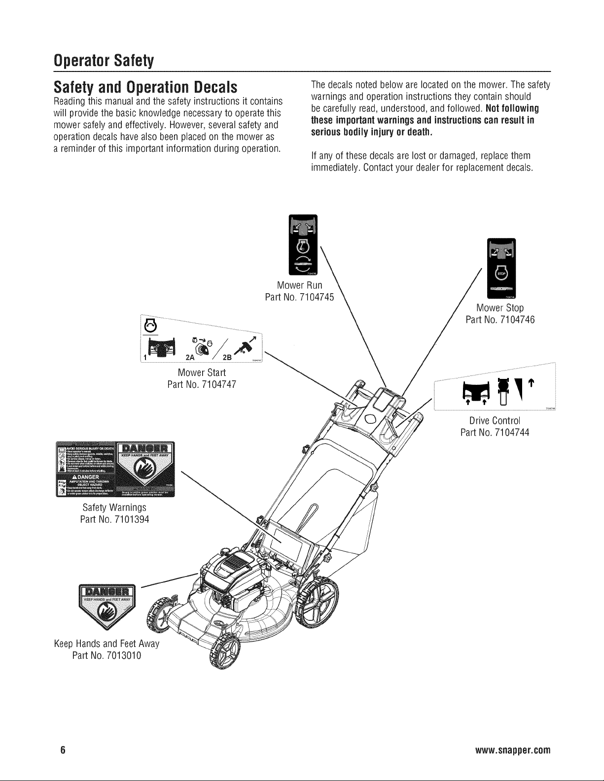
Safety and OperationDecals
Readingthis manual andthe safety instructions it contains
will provide the basic knowledge necessaryto operatethis
mower safelyand effectively. However,severalsafety and
operation decals have also been placedon the mower as
a reminder of this important information during operation.
Part No. 7104745
Thedecalsnoted below are located on the mower. Thesafety
warnings and operation instructions they contain should
be carefully read, understood, and followed. Not following
theseimportantwarningsand instructionscan result in
seriousbodilyinjuryor death.
If any of thesedecals are lost or damaged, replacethem
immediately. Contactyour dealer for replacement decals.
Mower Run
Mower Stop
Part No. 7104746
SafetyWarnings
Part No. 7101394
KeepHandsand FeetAway
Part No. 7013010
Mower Start
PartNo.7104747
DriveControl
PartNo.7104744
6 www.snapper.com
Page 7
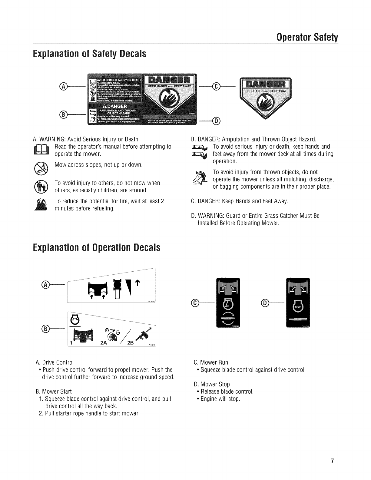
Explanationof Safety Decals
OperatorSafety
A. WARNING:Avoid Serious injury or Death
Readthe operator's manualbefore attempting to
operatethe mower.
Mow across slopes, not up or down.
®
®
Explanationof Operation Decals
To avoid injury to others, do not mow when
others, especiallychildren, arearound.
To reducethe potential for fire, wait at least2
minutes before refueling.
B. DANGER:Amputation and Thrown Object Hazard.
To avoid serious injury or death, keep hands and
feet away from the mower deck at all times during
operation.
_ To avoid injury from thrown objects, do not
"-?::i:_":_operatethe mower unlessall mulching, discharge,
or baggingcomponents arein their proper place.
C. DANGER:KeepHandsand FeetAway.
D. WARNING:Guardor EntireGrass CatcherMust Be
installed BeforeOperating Mower.
7,04747_
A. Drive Control
• Push drive control forward to propel mower. Push the
drive control further forward to increaseground speed.
B. Mower Start
1. Squeezeblade control against drive control, and pull
drive control all the way back.
2. Pull starter rope handleto start mower.
C. Mower Run
• Squeezebladecontrol against drive control.
D. Mower Stop
• Releasebladecontrol.
• Enginewill stop.
Page 8
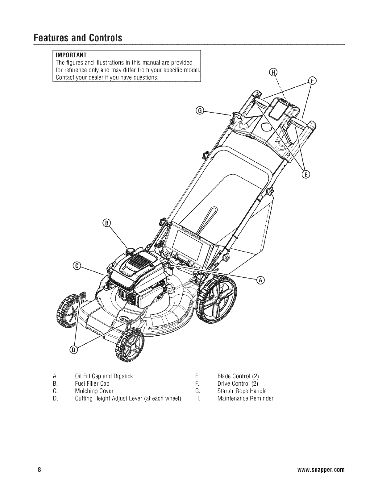
Featuresand Controls
IMPORTANT
Thefigures and illustrationsin this manual are provided
for referenceonly and may differ from your specific model.
Contactyour dealer if you have questions.
®
\
\
/
A.
B.
C.
D.
8 www.snapper.corn
Oil Fill Capand Dipstick E.
FuelFillerCap F.
Mulching Cover G.
Cutting Height Adjust Lever(at eachwheel) H.
BladeControl (2)
Drive Control (2)
Starter Rope Handle
MaintenanceReminder
Page 9
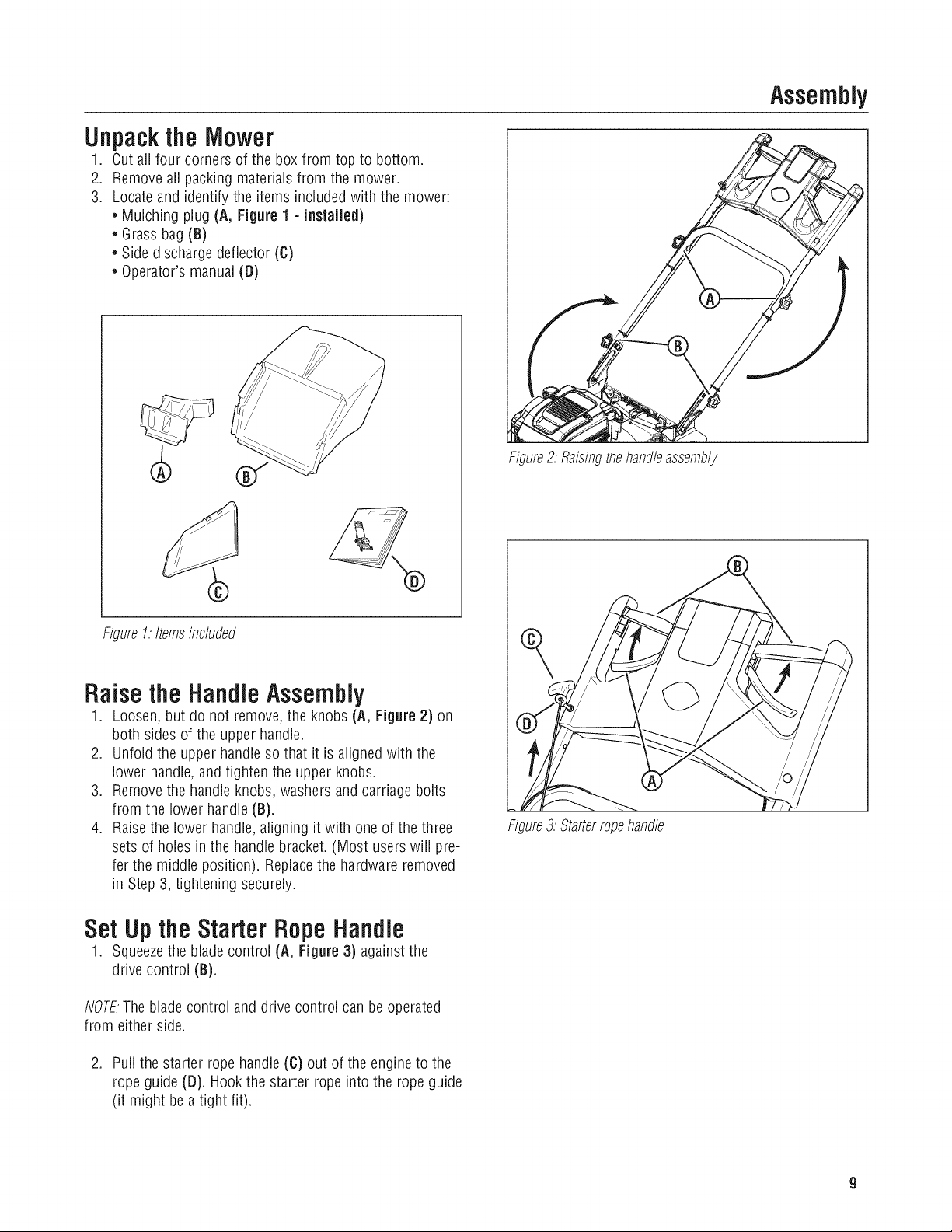
Assembly
Unpackthe
1.
Cut all four corners of the box from top to bottom.
2,
Removeall packing materials from the mower.
3.
Locate and identify the items included with the mower:
* Mulching plug (A, Figure 1 - installed)
* Grass bag (B)
* Side discharge deflector (C)
* Operator's manual (D)
Mower
Figure2:Raisingthehand/eassembly
Figure1:Itemsinc/uded
RaisetheHandleAssembly
1. Loosen, but do not remove,the knobs (A, Figure 2) on
both sides of the upper handle.
2. Unfold the upper handleso that it is aligned with the
lower handle,and tighten the upper knobs.
3. Removethe handle knobs, washers and carriagebolts
from the lower handle (B).
4. Raisethe lower handle,aligning it with oneof the three
sets of holes in the handle bracket. (Most userswill pre-
fer the middle position). Replacethe hardware removed
in Step 3, tightening securely.
Set Upthe Starter Rope Handle
1. Squeezethe bladecontrol (A, Figure 3) againstthe
drive control (B).
NOTE.The bladecontrol and drive control can beoperated
from either side.
2. Pull the starter rope handle(C) out of the engine to the
rope guide ([I). Hookthe starter rope into the rope guide
(it might be a tight fit).
Figure3.Starterropehand/e
Page 10
Operation
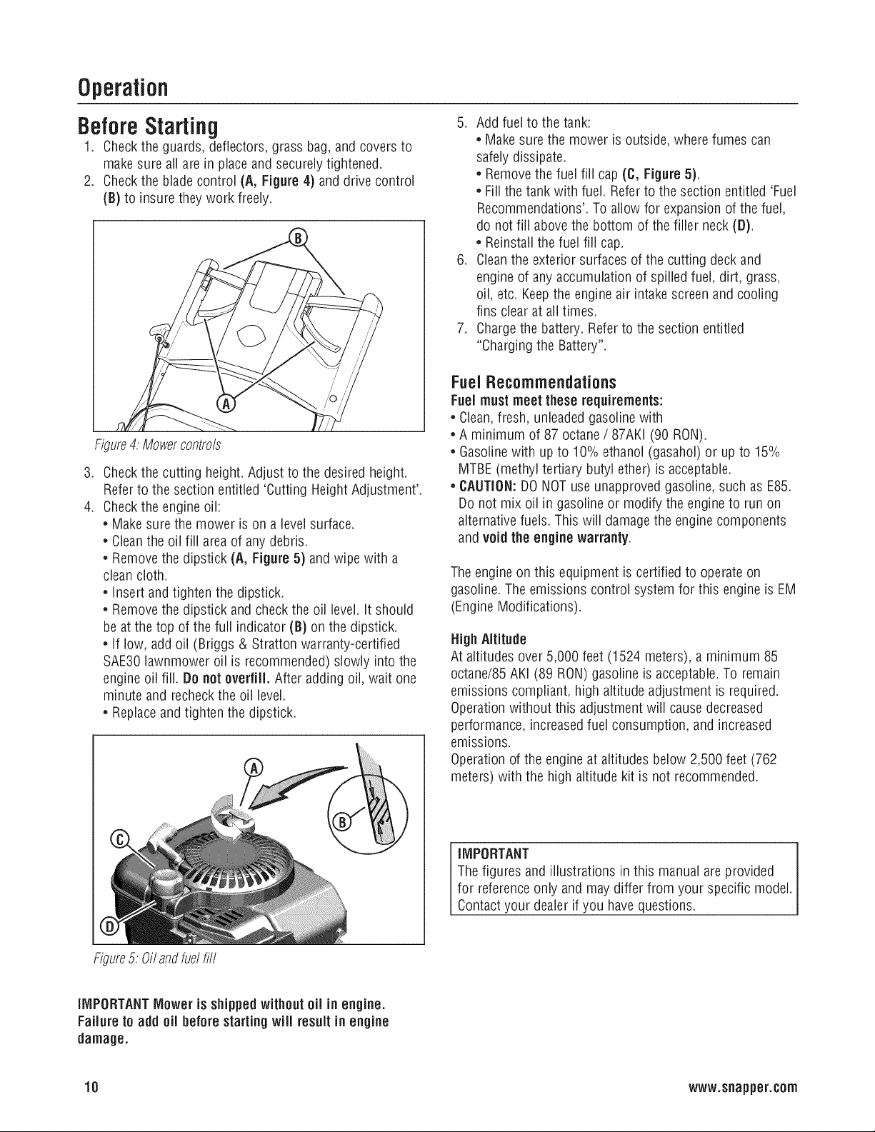
Before
1.
2.
Figure4:Mowercontrols
.
4.
Starting
Checkthe guards, deflectors, grass bag,and coversto
make sure all are in place and securelytightened.
Checkthe blade control (A, Figure 4) and drive control
(B) to insure they work freely.
Checkthe cutting height. Adjust to the desiredheight.
Refer to the section entitled 'Cutting Height Adjustment'.
Checkthe engine oil:
• Make sure the mower is on a level surface.
• Cleanthe oil fill areaof anydebris.
• Remove the dipstick (A, Figure 5) andwipe with a
cleancloth.
• Insert andtighten the dipstick.
• Remove the dipstick and checkthe oil level. It should
be at the top of the full indicator (B) on the dipstick.
• If low, add oil (Briggs & Stratton warranty-certified
SAE30lawnmower oil is recommended) slowly into the
engine oil fill. Do notoverfill. After adding oil, wait one
minute and recheckthe oil level.
• Replaceandtighten the dipstick.
5. Addfuel to the tank:
• Make sure the mower is outside, where fumes can
safely dissipate.
• Removethe fuel fill cap (C, Figure 5).
• Fill the tank with fuel. Referto the section entitled 'Fuel
Recommendations'.To allow for expansion of the fuel,
do not fill abovethe bottom of the filler neck (D).
• Reinstall the fuel fill cap.
6. Cleanthe exterior surfaces of the cutting deck and
engine of any accumulationof spilled fuel, dirt, grass,
oil, etc. Keepthe engine air intakescreen and cooling
fins clear at all times.
7. Chargethe battery. Refer to the section entitled
"Charging the Battery".
FuelRecommendations
Fuel mustmeet these requirements:
* Clean,fresh, unleaded gasolinewith
, A minimum of 87 octane / 87AKI (90 RON).
, Gasolinewith up to 10% ethanol (gasahol) or up to 15%
MTBE(methyl tertiary butyl ether) is acceptable.
* CAUTION:DONOTuse unapproved gasoline, such as E85.
Do not mix oil in gasoline or modify the engineto run on
alternative fuels. This wiii damagethe engine components
and void the engine warranty.
Theengineon this equipment is certified to operateon
gasoline. Theemissions control systemfor this engine is EM
(Engine Modifications).
High Altitude
At altitudes over 5,000 feet (1524 meters), a minimum 85
octane/85AKi (89 RON)gasoline is acceptable.To remain
emissions compliant, high altitude adjustment is required.
Operationwithout this adjustment will cause decreased
performance, increasedfuel consumption, and increased
emissions.
Operationof the engineat altitudes below 2,500 feet (762
meters) with the high altitude kit is not recommended.
IMPORTANT
Thefigures and illustrations in this manualareprovided
for referenceonly and may differ from your specific model.
Contactyour dealer if you have questions.
Figure5:0il andfuelfill
iMPORTANTMower is shippedwithoutoil in engine.
Failureto add oil before startingwill result in engine
damage.
10 www.snapper.com
Page 11
Starting the Mower
Theengineon this mower is equipped with a ReadyStart®
system, which featuresa temperature-controlled automatic
choke, it does not have a manual choke or a primer.
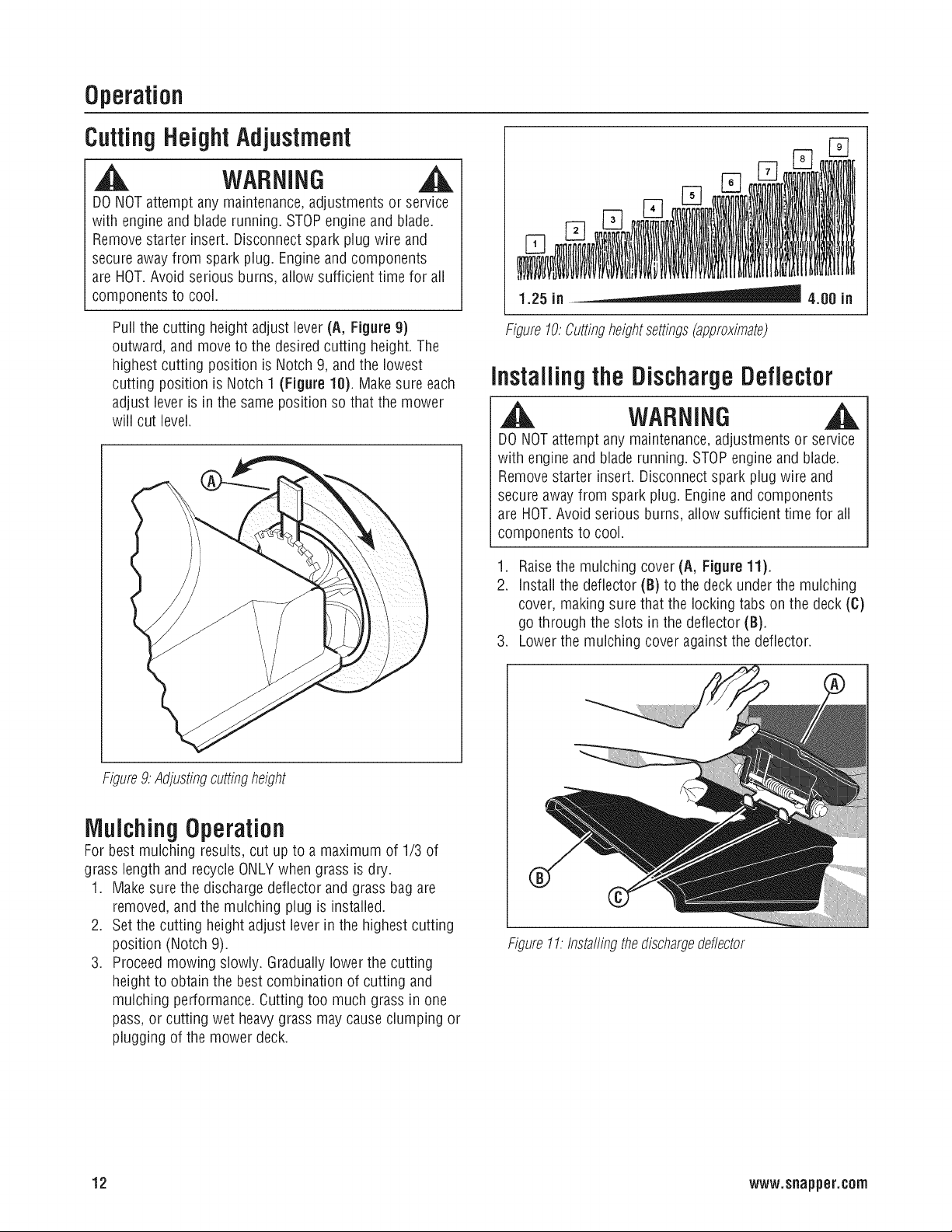
1. Squeezethe bladecontrol (A, Figure 6) againstthe
drive control (B).
2. Pull the drive control all the way backto the neutral
position.
NOTEThe blade control and drive control can be operated
from either side.
3. Pull the rope start handle (6) to start the engine.
4. To stop the engine (and blade), releasethe blade
control.
5. After the engine starts, allow a brief warm-up until the
engine runs smooth before beginning mower operation.
Operation
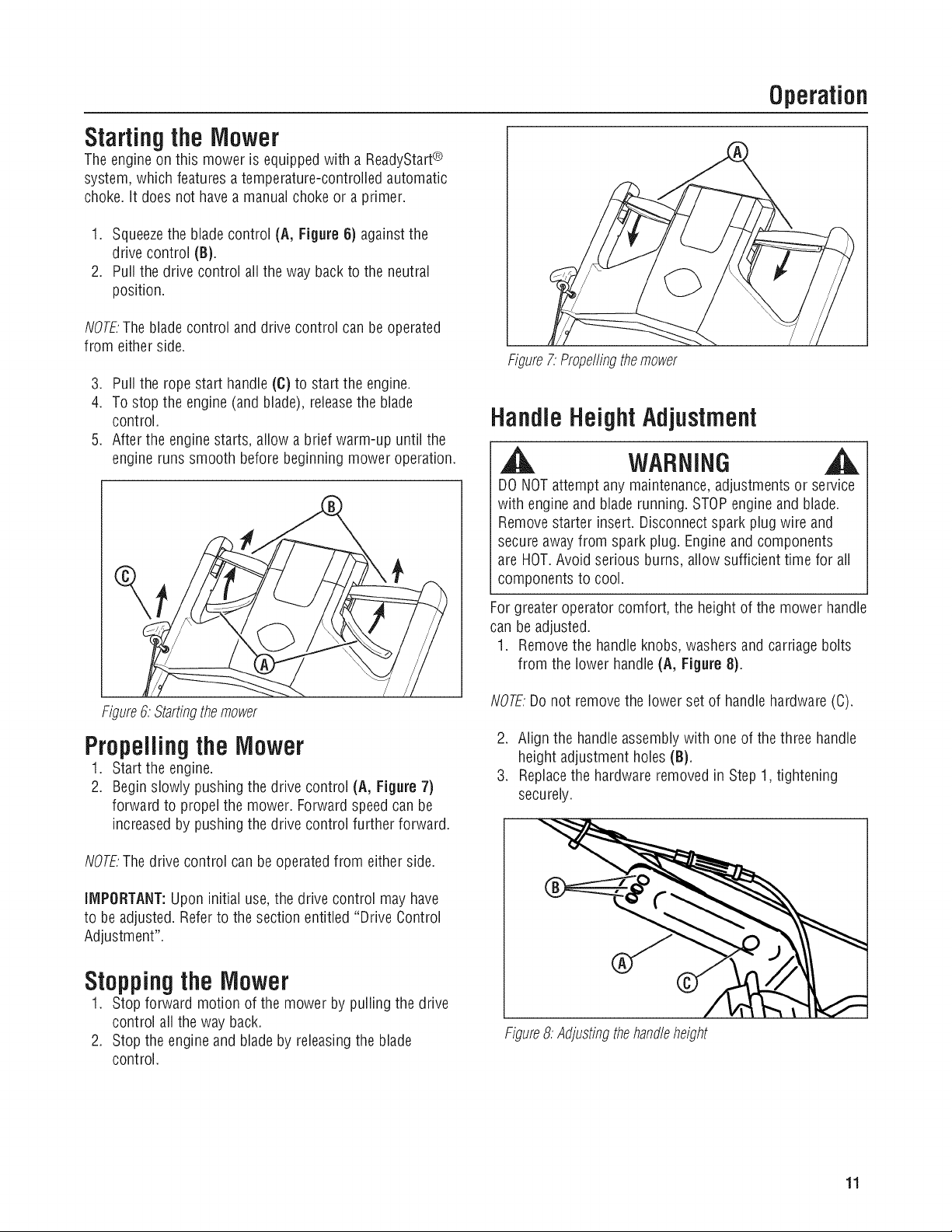
Figure7:Propellingthemower
HandleHeight Adjustment
| WARNING
DONOTattempt any maintenance,adjustmentsor service
with engine and blade running. STOPengine and blade.
Removestarter insert. Disconnectspark plug wire and
secure awayfrom spark plug. Engineand components
are HOT.Avoid serious burns, allow sufficient time for all
components to cool.
Figure6:Startingthemower
Propelling the Mower
1. Start the engine.
2. Begin slowly pushing the drive control (A, Figure 7)
forward to propel the mower. Forward speed can be
increased by pushing the drive control further forward.
NOTEThe drive control canbe operated from either side.
IMPORTANT:Upon initial use,the drive control may have
to be adjusted. Referto the section entitled "Drive Control
Adjustment".
Stoppingthe Mower
1. Stop forward motion of the mower by pulling the drive
control all the way back.
2. Stop the engine and blade by releasingthe blade
control.
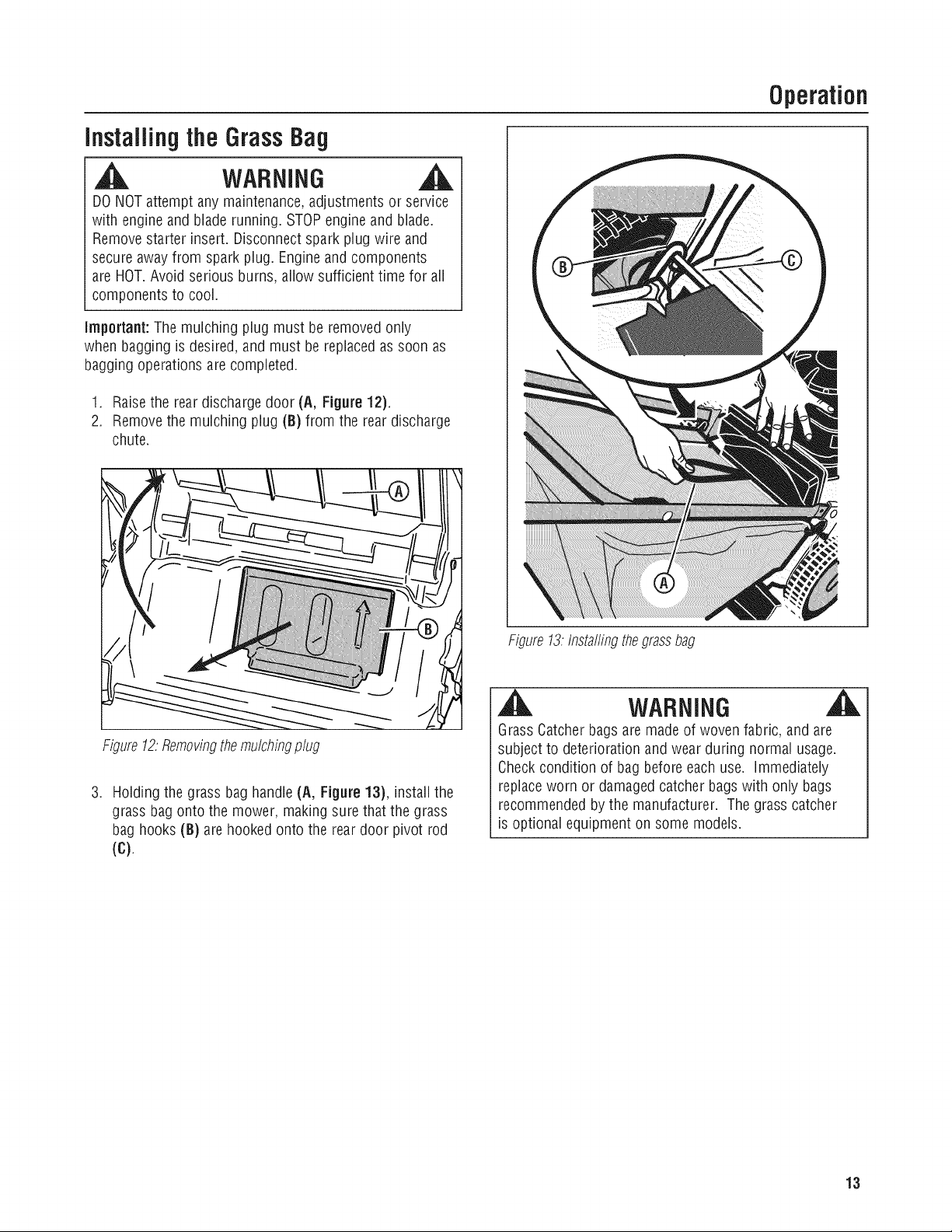
Forgreater operator comfort, the height of the mower handle
can be adjusted.
1. Removethe handle knobs, washersand carriagebolts
from the lower handle (A, Figure 8).
NOTE.Donot removethe lower set of handle hardware (C).
2. Alignthe handle assemblywith one of the three handle
height adjustment holes (B).
3. Replacethe hardware removed in Step 1, tightening
securely.
Figure8:Adjustingthehandleheight
11
Page 12
Operation
Cutting HeightAdjustment
WARNING ,A
DONOTattempt any maintenance,adjustments or service
with engine and blade running. STOPengine and blade.
Removestarter insert. Disconnectspark plugwire and
secure awayfrom spark plug. Engine and components
are HOT.Avoid serious burns, allow sufficient time for all
components to cool.
1.25 in 4.00 in
Pull the cutting height adjust lever(A, Figure 9)
outward, and moveto the desiredcutting height. The
highest cutting position is Notch 9, and the lowest
cutting position is Notch 1 (Figure 10). Makesure each
adjust lever is in the same position so that the mower
will cut level.
Figure9:Adjustingcuttingheight
Figure10:Cuttingheightsettings(approximate)
Installingthe DischargeDeflector
WARNING
DONOTattempt any maintenance,adjustmentsor service
with engine and blade running. STOPengine and blade.
Removestarter insert. Disconnectspark plug wire and
secure awayfrom spark plug. Engineand components
are HOT.Avoid serious burns, allow sufficient time for all
components to cool.
1. Raisethe mulching cover(A, Figure 11).
2. Install the deflector (B)to the deck under the mulching
cover, making sure that the locking tabs on the deck (C)
go through the slots in the deflector (B).
3. Lowerthe mulching cover against the deflector.
Mulching Operation
For best mulching results, cut up to a maximum of 1/3 of
grass length andrecycle ONLYwhen grass is dry.
1. Make sure the discharge deflector and grass bag are
removed, and the mulching plug is installed.
2. Setthe cutting height adjust lever in the highest cutting
position (Notch 9).
3. Proceedmowing slowly. Graduallylower the cutting
height to obtain the bestcombination of cutting and
mulching performance. Cutting too much grass in one
pass, or cutting wet heavygrass maycause clumping or
plugging of the mower deck.
12 www.snapper.corn
Figure11:Insta//ingthedischargedeflector
Page 13
nstallingthe GrassBag
WARNING ,A
DONOTattempt any maintenance,adjustments or service
with engine and blade running. STOPengine and blade.
Removestarter insert.Disconnect spark plug wire and
secure awayfrom spark plug. Engine and components
are HOT.Avoid serious burns, allow sufficient time for all
components to cool.
Important: The mulching plug must be removed only
when bagging is desired, and must be replacedas soon as
bagging operations are completed.
1. Raisethe rear discharge door (A, Figure 12).
2. Removethe mulching plug (B) from the reardischarge
chute.
Operation
Figure12:Removingthemu/chingp/ug
.
Holding the grass bag handle (A, Figure 13), install the
grass bag onto the mower, making sure that the grass
bag hooks (B) are hooked onto the reardoor pivot rod
(c),
Figure13:Insta//ingthegrassbag
WARNING
Grass Catcherbags are madeof woven fabric, and are
subject to deterioration and wear during normal usage.
Checkcondition of bag before each use. immediately
replaceworn or damagedcatcher bagswith only bags
recommended bythe manufacturer. The grass catcher
is optional equipment on some models.
13
Page 14
Operalion
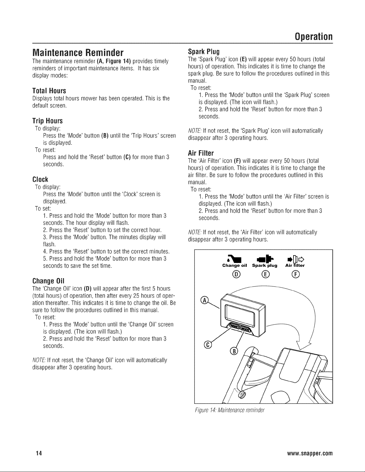
Mainlenance Reminder
The maintenancereminder (A, Figure14) providestimely
reminders of important maintenanceitems. It has six
display modes:
Total Hours
Displays total hours mower hasbeen operated.This is the
default screen.
Trip Hours
To display:
Press the 'Mode' button (B) until the 'Trip Hours' screen
is displayed.
To reset:
Press and hold the 'Reset' button (C) for more than 3
seconds.
Clock
To display:
Press the 'Mode' button until the 'Clock' screenis
displayed.
To set:
1. Pressand hold the 'Mode' button for more than 3
seconds. Thehour display will flash.
2. Pressthe 'Reset' button to set the correct hour.
3. Press
flash.
4. Press
5. Press
seconds
Change Oil
The 'ChangeOil' icon (D) will appear after the first 5 hours
(total hours) of operation, then after every25 hours of oper-
ation thereafter. This indicates it is time to changethe oil. Be
sure to follow the procedures outlined in this manual.
To reset:
1. Pressthe 'Mode' button until the 'ChangeOil' screen
is displayed. (The icon will flash.)
2. Pressand hold the 'Reset' button for more than 3
seconds.
the 'Mode' button. The minutes displaywill
the 'Reset' button to setthe correct minutes.
and hold the 'Mode' button for more than 3
to savethe set time.
Spark Plug
The'Spark Plug' icon (E) will appear every 50 hours (total
hours) of operation. This indicates it is time to changethe
spark plug. Besureto follow the procedures outlined in this
manual.
To reset:
1. Pressthe 'Mode' button until the 'Spark Plug' screen
is displayed. (The icon will flash.)
2. Pressand hold the 'Reset' button for more than 3
seconds.
NOTE:if not reset,the 'Spark Plug' icon will automatically
disappearafter 3 operating hours.
Air Filter
The'Air Filter' icon (F) will appearevery 50 hours (total
hours) of operation. This indicates it is time to changethe
air filter. Be sureto follow the procedures outlined in this
manual.
To reset:
1. Pressthe 'Mode' button until the 'Air Filter' screen is
displayed. (Theicon will flash.)
2. Pressand hold the 'Reset' button for more than 3
seconds.
NOTE;If not reset,the 'Air Filter' icon will automatically
disappearafter 3 operating hours.
Change oil Spark plug Air filter
@ ® ®
NOTEIf not reset,the 'ChangeOil' icon will automatically
disappearafter 3 operating hours.
Figure14:Maintenancereminder
14 www.snapper.c0rn
Page 15
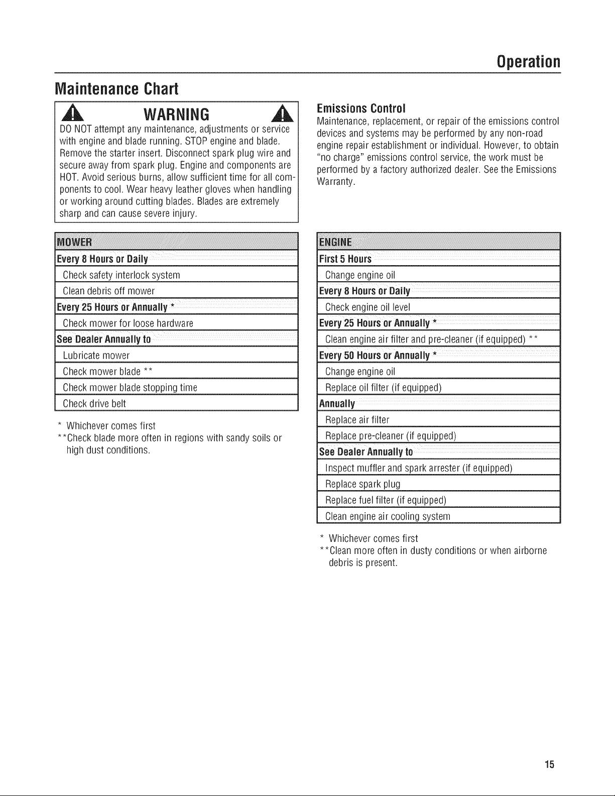
MaintenanceChart
Operation
WAeNING
DONOTattempt any maintenance,adjustments or service
with engine and blade running. STOPengine and blade.
Removethe starter insert. Disconnectspark plug wire and
secure awayfrom spark plug. Engine and components are
HOT.Avoid serious burns, allow sufficient time for all com-
ponents to cool. Wearheavy leather gloves when handling
or working around cutting blades. Bladesareextremely
sharp and can causesevere injury.
ii!i i !!! i!ii i! ! !! !! ! ! !! ! i!! !i iiiiiiiiiiiiiiiiiiiiiiiiiiiiiiiiiiiiiiiiiiiiiiiiiiiiiiiiiiiiiiiiiiiiiiiiiiiiiiiiiiiiiiiiiiiiiiiiiiiiiiiiiiiiiiiiiiiiiiiiiiiiiiiiiiiiiiiiiiiiiiiiiiiiiiiiiiiiiiiiiiiiiiiiiiiiiiiiiiiiiiiiiiiiiiiiiiiiiiiiiiiiiiiiiiiiiiiiiiiiiiiiiiiiiiiiiiiiiiiiiiiiiiiiiiiiiiiii!iiiiiiiiiiiiii!iiiiiiiiiiiiiiiiiiiiiiiiiiiiiiiiiii!!iiiiiiiiiiiiiiiiiiiiiiiiiiiiiiiiiiiiiiiiiiiiiiiiiiiiiiiiiiiiiiiiiiiiiiiiiiiiiiiiiiiiiiiiiiiiiiiiiiiiiiiiiiiiiiiiiiiiiiiiiiiiiiiiiiiiiiiiiiiiiiiiiiiiiiiiiiiiiiiiiiiiiiiiiiiiiiiiiiiiiiiiiiiiiiiiiiiiiiiiiiiiiiiiiiiiiiiiiiiiiiiiiiiiiiiiiiiiiiiiiiiiiiiiiiiiiiiiiiiiiiiiiiiiiiiiiiiiiiiiiiiiiiiiiiiiiiiiiiiiiiiiiiiiiiiiiiiiiiiiiiiiiiiiiiiiiiiiiiiiiiiiiiiiiiiiiiiiiiiiiiiiiiiiiiiiiiiiiiiiiiiiiiiiiiiiiiiiiiiiiiiiiiiiiiiiiiiiiiiiiiiiiiii!i!
Every8 Hoursor Daily
Checksafety interlock system
Cleandebris off mower
Checkmower for loose hardware
See Dealer Annually to
Lubricate mower
Checkmower blade **
Checkmower bladestopping time
Checkdrive belt
* Whichevercomes first
**Check blademore often in regions with sandy soils or
high dust conditions.
Emissions Control
Maintenance, replacement,or repair of the emissions control
devicesandsystems may beperformed byany non-road
engine repair establishment or individual. However,to obtain
"no charge" emissions control service, the work must be
performed by afactory authorized dealer.Seethe Emissions
Warranty.
i i: ! ! i i! ii !! ! i i i i!i iiiiii iiiiiii iiiiiiiiiiiiiiiiiiiiiiiiiiiiiiiiiiiiiiiiiiiiiiiiiiiiiiiiiiiiiiiiiiiiiiiiiiiiiiiiiiiiiiiiiiiiiiiiiiiiii
First5 Hours
Changeengineoil
Every8 Hours or Daily ....................
Checkengineoil level
Every25Hoursor Annually *
Cleanengineair filter and pre-cleaner(if equipped) **
Every50 Hoursor Annually *
Changeengineoil
Replaceoil filter (if equipped)
Annually
Replaceair filter
Replacepre-cleaner(if equipped)
See Dealer Annually to
Inspect muffler and spark arrester (if equipped)
Replacespark plug
Replacefuel filter (if equipped)
Cleanengineair cooling system
* Whichevercomes first
**Clean more often in dusty conditions or when airborne
debris is present.
15
Page 16

Maintenance
ChangeEngineOil
,A WARNING
DONOTattempt any maintenance,adjustments or service
with engine and blade running. STOPengine and blade.
Removestarter insert.Disconnectspark plug wire and
secure awayfrom spark plug. Engine and components
are HOT.Avoid serious burns, allow sufficient time for all
components to cool.
1. Drain the fuel tankcompletely.
2. Removethe dipstick (A, Figure 15), then turn the
mower on its side. Allow the oil to drain from the oil fill
tube into an appropriate container. Disposeof used oil
properly.
3. Placethe mower upright, then fill the enginewith
engine oil to the 'full' mark on the dipstick. Briggs &
Stratton warranty-certified SAE30lawnmower oil is
recommended. Do notoverfill.
ServiceAir Filter
WARNING
Neverstart or run the engine with the air cleanerassembly
(if equipped) or the air filter (if equipped) removed.
Referto the engine owner's manualfor airfilter service
instructions.
Figure15:Drainingtheengineoi/
®
16 www.snapper.corn
Page 17

Maintenance
CheckSafety InterlockSystem
1. Start the mower.
2. Releasethe blade control. The engine must stop within
3 seconds.
if the engine does not stop, do notuse the mower.Bring the
mower to an authorizeddealer for service.
CleanDebrisOff Mower
WARNING
DONOTattempt any maintenance,adjustments or service
with engine and blade running. STOPengine and blade.
Removestarter insert. Disconnectspark plugwire and
secure awayfrom spark plug. Engine and components are
HOT.Avoid serious burns, allow sufficient time for all com-
ponents to cool. Wearheavy leather gloves when handling
or working around cutting blades. Bladesareextremely
sharp and can causesevere injury.
1. Cleandirt and debris from the top of the mower deck.
2. Cleanany debris buildup on or around the engine, etc.
While cleaning, check componentsfor wear or damage.
Replaceworn or damagedcomponents immediately.
11.Start the engineand run for 2-3 minutes, to allow the
underside of the mower deck to dry.
Figure16;Washoutport
WashoutPort
WARNING ,A
* Useappropriate eyeprotection.
, Keeppeopleand pets out of the area.
, Stay behind the handlewhile the engine is running.
, Do not attempt mowing operations while using the
washout port.
, Do not attempt to look under or reach under the mower
deck for any reasonwhile using the washout port.
Serious injury can result.
Thewashout port allows hands-free cleaningof the
underside of the mower deck.To usethe washout port:
1. Be surethe grass bag and sidedischargedeflector are
removed.
2. Setthe height of cut to the lowest position.
3. Move the mower to a level, pavedsurface.
4. Stop the engine.
5. Connectthe male end of a standard garden hoseto the
washout port connector (A, Figure 16).
6. Turn on thewater supply to the garden hose.
7. Start the engine and run until no more debris emerges
from under the mower deck.
8. Stop the engine.
9. Turn off the water supply to the garden hose.
10.Disconnect the garden hosefrom the washout port
connector.
17
Page 18

Maintenance
DriveControlAdjustment
,A WARNINa ,A
DONOTattempt any maintenance,adjustments or service
with engine and blade running. STOPengine and blade.
Removestarter insert.Disconnectspark plug wire and
secure awayfrom spark plug. Engine and components
are HOT.Avoid serious burns, allow sufficient time for all
components to cool.
Thedrive control (A, Figure 17) should engagethe transmis-
sion when the control is pushed forward, and should disen-
gagethe transmission when pulled all the way back.
Figure17.Drivecontrol
If the transmission does not engageor disengage,
adjustment may be performed as follows:
• If the transmission does not engage,rotatethe turnbuckle
(A, Figure18) one-half turn to movethe ferrules (B) out
from the turnbuckle. Checkand repeatasneeded.
• If the transmission does not disengage, rotate the turn-
buckle one-half turn to move the ferrules intoward the turn-
buckle. Checkand repeatas needed.
StorageProcedure
WARNING
DONOTattempt any maintenance,adjustmentsor service
with engine and blade running. STOPengine and blade.
Removestarter insert. Disconnectspark plug wire and
secure awayfrom spark plug. Engineand components are
HOT.Avoid serious burns, allow sufficient time for all com-
ponents to cool. Wearheavy leather gloves when handling
or working around cutting blades. Bladesareextremely
sharp and can causesevere injury.
Preparethe mower for "end of season"storage as follows:
1. Disconnectthe spark plug wire and secureaway from
the spark plug.
2. Drainthe fuel tank and let the engine run until all fuel is
out of the carburetor.
NOTE.If using a fuel stabilizer,there is no need to drain the
fuel tank. Referto the section entitled 'Fuel System'.
3. Usea brush or compressed air to remove loose debris,
then use a damp cloth to wipe down the unit.
4. Tilt the mower up on its rear wheels and inspect the
underside of the deck. (Do not tilt the mower with the
spark plug or carburetor down.) Scrape away stubborn
accumulation of grasswith a putty knife and/or wire
brush.
5. Lubricateall exposed metal with a light coating of oil to
prevent corrosion.
6. Carefullyfold the handles,flexing the control cablesto
prevent cable damage.
7. Store the mower in a shed or other dry area, protected
from weather.
FuelSystem
Fuelcan becomestale when stored over 30 days.Stale fuel
causesacid and gum depositsto form in thefuel system or
on essential carburetor parts. To keep fuel fresh, use Bfiggs
& Stratton FRESHSTART® fuel stabilizer, availableas a
liquid additive or a drip concentrate cartridge.
Thereis no need to drain gasolinefrom the engine if a fuel
stabilizer is added according to instructions. Run the engine
for 2 minutes to circulatethe stabilizer throughout the fuel
system. The engine and fuel canthen be stored up to 24
Figure18;Adjustingthedrivecable
Caution: Incorrect adjustment can cause premature wear
and/or damageto the wheel drive components.
18 www.snapper.corn
months.
If gasoline in the enginehasnot beentreated with a fuel
stabilizer, it must be drained into an approvedcontainer. Run
the engine until it stops from lack of fuel. Theuse of a fuel
stabilizer in the storage container is recommendedto
maintain freshness.
Page 19

Troubleshooting
PROBLEM PROBABLECAUSE CORRECTIVEACTION
EngineWill Not Start 1. Fuel tank empty. 1. Fill fuel tank with fresh fuel.
2. Spark plug wire disconnected. 2. Placespark plugwire onto spark plug.
Engine Stalls or Loses 1. Bladecontrol is releasedor is not being held 1. Bladecontrol should be held securelyagainst
PowerAfter Running securelyagainst drive control, drive control at all times during operation.
2. Fueltank empty. 2. Fill with fuel to proper level.
3. Engine pre-cleaner and/or air cleanerdirty. 3. Cleanor replaceprecleanerand/or air cleaner.
4. Spark plug fouled or gap set improperly. 4. Service spark plug.
5. Water, debris or stale fuel in fuel system. 5. Drain and cleanfuel system.
ExcessiveVibration 1. Damaged,out of balanceor bent mower blade.1. Contactauthorized dealer.
2. Loosebladecomponents. 2. Contact authorized dealer.
3. Looseor missing air lift (if equipped). 3. Contact authorized dealer.
4. Lumpy or frayed belt. 4. Contact authorized dealer.
Mower Will Not Move/ 1. Build-up of debris on or around drive 1. Cleandebris.
Loss Of Traction components.
2. Transmission cableadjustment required. 2. Adjust transmission cable.
3. Drive belt requires replacement. 3. Contact authorized dealer.
4. Damagedtransmission. 4. Contact authorized dealer.
Cutting Grass Improperly1. Cutting height too low or high. 1. Adjust cutting height.
2. Forward speed too fast. 2. Adjust to a slower speed.
3. Cutting blade dull or damaged. 3. Contact authorized dealer.
Poor Grass Discharge 1. Forward speed too fast. 1. Adjust to a slower speed.
2. Grass is wet. 2. Mow when grass is dry.
3. Excessivelyworn or damaged blade. 3. Contact authorized dealer.
4. Build up of grass clippings and debris under 4. Cleandeck.
deck.
5. improper blade installed on deck. 5. Contact authorized dealer.
6. Bladeinstalled improperly on deck. 6. Contact authorized dealer.
Oil Leaking 1. Loosedipstick. 1. Make sure dipstick/oil filler cap is securely in
)lace.
2. Loosedrain plug. 2. Checkand tighten drain plug.
3. Oil levelis overfilled. 3. Drain excessoil.
4. Damagedoil seals. 4. Contact authorized dealer.
19
Page 20

Warranties
LiMiTED WARRANTY
Briggs & Stratton Power Products Group, LLC will repair and/or replace, free of charge, any part(s) of the equipment that is
defective in material or workmanship or both. Briggs & Stratton Corporation will repair and/or replace, free of charge, any
part(s) of the ariggs and Stratton engine* (if equipped)that is defective in material or workmanship or both. Transportation
charges on product submitted for repair or replacement under this warranty must be borne by purchaser. This warranty is
effective for the time periods and subject to the conditions stated below. For warranty service, find the nearest Authorized
Service Dealer using our dealer Iocator at www.BriggsandStratton.com or www.Snapper.com.
There is no other express warranty. Implied warranties, including those of merchantability and fitness for a particular
purpose, are limited to one year from purchase or to the extent permitted by law. Liability for incidental or consequential
damages are excluded to the extent exclusion is permitted by law.
Some states or countries do not allow limitations on how long an implied warranty lasts, and some states or countries do
not allow the exclusion or limitation of incidental or consequential damages, so the above limitation and exclusion may not
apply to you. This warranty gives you specific legal rights and you may also have other rights which vary from state to state
iiiiiiorcountrytocountry
The warranty period begins on the date of purchase by the first retail consumer or commercial end user, and continues for the
period of time stated above. "Consumer use" means personal residential household use by a retail consumer. "Commercial
use" means all other uses, including use for commercial, income producing or rental purposes. Once product has experienced
commercial use, it shall thereafter be considered as commercial use for purposes of this warranty.
No warranty registration is necessary to obtain warranty on Briggs & Stratton products. Save your proof of purchase receipt. If you
do not provide proof of the initial purchase date at the time warranty service is requested, the manufacturing date of the product will
be used to determine warranty eligibility.
We welcome warranty repair and apologize to you for being inconvenienced. Warranty service is available only through servicing
dealers authorized by Briggs & Stratton or BSPPG, LLC.
Most warranty repairs are handled routinely, but sometimes requests for warranty service may not be appropriate. This warranty
only covers defects in materials or workmanship. It does not cover damage caused by improper use or abuse, improper
maintenance or repair, normal wear and tear, or stale or unapproved fuel.
improper Use and Abuse - The proper, intended use of this product is described in the Operator's Manual. Using the product in
a way not described in the Operator's Manual or using the product after it has been damaged will void your warranty. Warranty is
not allowed if the serial number on the product has been removed or the product has been altered or modified in any way, or if the
product has evidence of abuse such as impact damage, or water/chemical corrosion damage.
improper Maintenance or Repair - This product must be maintained according to the procedures and schedules provided in the
Operator's Manual, and serviced or repaired using genuine Briggs & Stratton parts. Damage caused by lack of maintenance or use
of non-original parts is not covered by warranty.
Normal Wear - Like all mechanical devices, your unit is subject to wear even when properly maintained. This warranty does not
cover repairs when normal use has exhausted the life of a part or the equipment. Maintenance and wear items such as filters,
belts, cutting blades, and brake pads (engine brake pads are covered) are not covered by warranty due to wear characteristics
alone, unless the cause is due to defects in material or workmanship.
Stale Fuel - In order to function correctly, this product requires fresh fuel that conforms to the criteria specified in the Operator's
Manual. Damage caused by stale fuel (carburetor leaks, clogged fuel tubes, sticking valves, etc) is not covered by warranty.
* Applies to Briggs and Stratton engines only. Warranty coverage of non-Briggs and Stratton engines is provided by the engine manufacturer.
20 www.snapper.c0rn
Page 21

Warranties
January 2011
Emissions Control Warranty Statement Your Warranty Rights And Obligations
The California Air Resources Board, U.S. EPA, and Briggs & Stratton (B&S) are
pleased to explain the emissions control system warranty on your Model Year
2011-2012 engine / equipment, In California, new small off-road engines and large
spark ignited engines less than or equal to 1.0 liter must be designed, built, and
equipped to meet the State's stringent anti-smog standards. B&S must warrant the
emissions control system on your engine / equipment for the periods of time listed below
provided there has been no abuse, neglect, or improper maintenance of your engine or
equipment.
Your emissions control system may include parts such as the carburetor or fuel injection
system, fuel tank, ignition system, and catalytic converter. Also included may be hoses,
belts, connectors, sensors, and other emissions-related assemblies,
Where a warrantable condition exists, B&S wilt repair your engine / equipment at no
cost to you including diagnosis, parts, and labor,
Manufacturer's Warranty Coverage:
Small off-road engines and large spark ignited engines less than or equal to 1.O liter are
warranted for three years. If any emissions-related part on your engine / equipment is
defective, the part will be repaired or replaced by B&S.
The following are specific provisions relative to your Emissions Control Warranty Coverage. It is in addition to the B&S engine warranty for non-regulated engines found in the
Operator's Manual.
1. Warranted Emissions Parts
Coverage under this warranty extends only to the parts listed below (the emissions
control systems parts) to the extent these parts were present on the engine
purchased.
a. Fuel Metering System
• Cold start enrichment system (soft choke)
• Carburetor and internal parts
• Fuel pump
• Fuel line, fuel line fittings, clamps
• Fuel tank, cap and tether
• Carbon canister
b. Air Induction System
• Air cleaner
• Intake manifold
• Purge and vent line
c. Ignition System
• Spark plug(s)
• Magneto ignition system
d. Catalyst System
• Catalytic converter
• Exhaust manifold
• Air injection system or pulse valve
e. Miscellaneous Items Used in Above Systems
• Vacuum, temperature, position, time sensitive valves and switches
• Connectors and assemblies
2. Length of Coverage
For a period of three years from date of original purchase, B&S warrants to the
original purchaser and each subsequent purchaser that the engine is designed,
built, and equipped so as to conform with all applicable regulations adopted by the
Air Resources Board; that it is free from defects in material and workmanship that
could cause the failure of a warranted part; and that it is identical in all material
respects to the engine described in the manufacturer's application for certification.
The warranty period begins on the date the engine is originally purchased.
Look For Relevant Emissions Durability Period and Air Index Information
Engines that are certified to meet the California Air Resources Board (CARB) small
off-road Emissions Standard must display information regarding the Emissions
Durability Period and the Air Index. Briggs & Stratton makes this information available to
the consumer on our emissions labels. The engine emissions label will indicate
certification information.
The Emissions Durability Period describes the number of hours of actual running time
for which the engine is certified to be emissions compliant, assuming proper
maintenance in accordance with the Operating & Maintenance Instructions. The
following categories are used:
Moderate:
Engine is certified to be emissions compliant for 125 hours of actual engine running
time.
Intermediate:
Engine is certified to be emissions compliant for 250 hours of actual engine running
time.
California, U.S. EPA, and Briggs & Stratton Corporation
Owner's Warranty Responsibilities:
* As tile engine / equipment owner, you are responsible for tile performance of the
required maintenance listed in your owner's manual. B&S recommends that you
retain atl receipts covering maintenance on your engine / equipment, but B&S
cannot deny warranty solely for the lack of receipts or your failure to ensure the
performance of all scheduled maintenance.
o As the engine / equipment owner, you should however be aware that B&S may deny
you warranty coverage if your engine / equipment or a part has failed due to abuse,
neglect, improper maintenance, or unapproved modifications.
o You are responsible for presenting your engine / equipment to a B&S distribution
center, servicing dealer, or other equivalent entity, as applicable, as soon as a
problem exists. The warranty repairs should be completed in a reasonable amount
of time, not to exceed 30 days. If you have any questions regarding your warranty
rights and responsibilities, you should contact B&S at (414) 259-5262.
Briggs & Stratton Emissions Control Warranty Provisions
The warranty on emissions-related parts is as follows:
• Any warranted part that is not scheduled for replacement as required
maintenance in the owner's manual supplied, is warranted for the warranty
period stated above. If any such part fails during the period of warranty
coverage, the part will be repaired or replaced by B&S at no charge to the
owner. Any such part repaired or replaced under the warranty wilt be warranted
for the remaining warranty period.
• Any warranted part that is scheduled only for regular inspection in the owner's
manual supplied, is warranted for the warranty period stated above. Any such
part repaired or replaced under warranty will be warranted for the remaining
warranty period.
• Any warranted part that is scheduled for replacement as required maintenance
in the owner's manual supplied, is warranted for the period of time prior to the
first scheduled replacement point for that part. If the part fails prior to the first
scheduled replacement, the part will be repaired or replaced by B&S at no
charge to the owner. Any such part repaired or replaced under warranty will be
warranted for the remainder of the period prior to the first scheduled
replacement point for the part.
• Add on or modified parts that are not exempted by the Air Resources Board
may not be used. The use of any non exempted add on or modified parts by
the owner will be grounds for disallowing a warranty claim. The manufacturer
wilt not be liable to warrant failures of warranted parts caused by the use of a
non exempted add on or modified part.
3.
Consequential Coverage
Coverage shall extend to the failure of any engine components caused by the
failure of any warranted emissions parts.
4.
Claims and Coverage Exclusions
Warranty claims shall be filed according to the provisions of the B&S engine
warranty policy. Warranty coverage does not apply to failures of emissions parts
that are not original equipment B&S parts or to parts that fail due to abuse, neglect,
or improper maintenance as set forth in the B&S engine warranty policy. B&S is not
liable for warranty coverage of failures of emissions parts caused by the use of
add-on or modified parts.
On Your Small Off-Road Engine Emissions Label
Extended:
Engine is certified to be emissions compliant for 500 hours of actual engine running
time. For example, a typical walk-behind lawn mower is used 20 to 25 hours per year,
Therefore, the Emissions Durability Period of an engine with an intermediate rating
would equate to 10 to 12 years.
Briggs & Stratton engines are certified to meet the United States Environmental
Protection Agency (USEPA) Phase 2 emissions standards. For Phase 2 certified
engines, the Emissions Compliance Period referred to on the Emissions Compliance
label indicates the number of operating hours for which the engine has been shown to
meet Federal emissions requirements.
For engines less than 225 cc displacement.
Category C = 125 hours, Category B = 250 hours, Category A = 500 hours
For engines of 225 cc or more displacement.
Category C = 250 hours, Category B = 500 hours, Category A = 1000 hours
Form No. 279967EN
Revision: -
21
Page 22

Notes
22 www.snapper.corn
Page 23

im
o
m
OO
oJ
Operate a walk-behind mower
across the face of slopes,
never up or down slopes.
Operate a riding mower
l
10 DEGREES 15 DEGREES
up or down slopes, never
across the face of slopes.
On a riding mower to determine if a slope is safeto mow: (1) disengage the blade(s), (2) put the unit in reverse, and (3) try to back straight up the
slope, if you can back up the slope, it is generally safe to mow. However, ifyou do not feel safe, or if you are not completely sure, use this guide
anddo not mow a slope that is greater than 15 degrees. Ifthe riding mower is used with a pull-behind or rear mounted attachment,
do not operate the unit on a slope that is greater than 10degrees.
A 15 degree slope is a hill that increases in height at approximately 2.5 feet in 10 feet,
A 10 degree slope is a hill that increases in height at approximately 1.7 feet in 10 feet.
slopes. Operate a riding mower up or down slopes, never across the face of slopes. Operate a walk-behind mower across the face
Use extreme care at all times, and avoid sudden turns or maneuvers. Follow other instructions in this manual for safety in mowing on
of slopes, never up or down slopes. Use extra care when operating on or near slopes and obstructions.
Page 24

Specifications
Mowsr
DeckSize(in) 22
Height of Out (in) 1.25 - 4
Transmission Type Variable Speed/Gear
Ground Speed (mph) 0 - 4.2
BladeTorque (ft-lbs) 40
Engine
Engine Power(ft-lbs) 7.00
Engine Displacement(cc) 190
FuelTankCapacity(qt) 1.0
PowerRating: The gross power rating for individual gas engine models is labeledin accordancewith SAE(Society of
Automotive Engineers)code J1940 (Small Engine Power & Torque Rating Procedure), and rating performancehas been
obtainedandcorrected in accordancewith SAEJ1995 (Revision2002-05). Torque valuesare derived at 3060 RPM; horse-
powervaluesare derived at 3600 RPM. Net power values are taken with exhaustand air cleanerinstalled whereas gross
powervaluesare collected without these attachments. Actual gross engine power will be higher than net engine power and
is affected by, among other things, ambient operating conditions and engine-to-engine variability. Giventhe wide array of
products on which engines are placed,the gas enginemay not developthe ratedgross powerwhen usedin agiven pieceof
power equipment.This difference is due to a variety of factors including, but not limited to, the variety of engine components
(air cleaner,exhaust, charging, cooling, carburetor, fuel pump, etc.), application limitations, ambient operating conditions
(temperature, humidity, altitude), and engine-to-enginevariability. Dueto manufacturing and capacity limitations, Briggs &
Stratton may substitute an engine of higher ratedpower for this Seriesengine.
Common Service Parts PartNumber
Mowsr
Mower Blade 7103288
Drive Belt 7103362
Page 25

Manual del usuario
_8oo_8 spxw_,o.w
N.___°de m.__OdelO_ Descripci6n 1
Page 26

Graciasper haber adquirido este cortac_spedSnapperdealta calidad. Le agradecemoslaconfianzaque
Ud. hadepositadoen la marcaSnapper.Sise manejay se realizael mantenimientoadecuadotal y come
se indicaen este manual,su cortacespedSnapperle proporcionar_a_osde funcionamientoliable.
Estemanual contieneinformaciOnde seguridadpara avisarlede los peligros y riesgos asociadoscon
el dispositivo y sobreel mode de evitarlos. Estam_quinaestAdiseSaday concebida_nicamenteparael
corte final decespedasentadoy no paracualquierotro propOsito.Esimportante que leay comprenda
estasinstrucciones con detenimiento antesde precedera arrancaro hacerfuncionar esteequipo.
Conserveestasinstruccionesoriginales para consultarlasen el future.
Fecha de compra
iVlinorista
N_rnerodetel_fono del vendedorminorista
Equipo
Motor
Namerode modelo
N_mero de serie
Modelo Tipo CCdigo
SNAPPERes una marca comercial de
Briggs & Stratton PowerProducts Group, LLC
Milwaukee, WI, EEUU.
Copyright © 2010, Briggs & Stratton Corporation
Milwaukee, WI, EEUU. Todos los derechos reservados.
Page 27

f
Indite
Seguridad del usuario ........................................................................... 4
Instruccionesdeseguridad.........................................................................................................4
Etiquetastransparentesdeseguridadyfuncionamiento.............................................................6
Caracteffsticas y rnandos........................................................................ 8
IVlontaje............................................................................................. 9
Operaci6n ......................................................................................... 10
Antesdeempezar......................................................................................................................10
Recomendacionessobrecombustible.......................................................................................10
Encendidodelcorta@sped.......................................................................................................11
PropulsiOndelcorta@sped......................................................................................................11
Ajustedealturadelmango.......................................................................................................11
Ajustedealturadecorte...........................................................................................................12
Funcionamientodeladesmenuzadora......................................................................................12
Instalaci6ndeldeflectordedescarga........................................................................................12
Instalaci6ndela bolsade@sped.............................................................................................13
Recordatoriodemantenimiento................................................................................................14
IVlantenirniento................................................................................... 15
Tablademantenimiento............................................................................................................15
Oambiarelaceitedelmotor......................................................................................................16
Hagael mantenimientodelfiltrodeaire...................................................................................16
Revisarelsistemadebloqueodeseguridad.............................................................................17
Limpiezadelosdesechosdel corta@sped...............................................................................17
Ajustedelcontroldelatransmisi6n.........................................................................................18
Procedimientodealmacenamiento...........................................................................................18
Soluci6nde problemas......................................................................... 19
Garantias.......................................................................................... 20
Sensor de inclinaci6n........................................................................... 23
ADVERTENCIA
Constituye una infracci6n del articulo 4442 delCalifornia
Public ResourceCode utiiizar u operar el motor en la
proximidades de terrenos boscosos o de rastrojo o que
est6n cubiertos de hierba a menos que el sistema de
escapeest6 equipado con un dispositivo antichispas,tal
y como se defineen la Secci6n 4442, que adem_s se
mantenga en un buenestado de funcionamiento. Otros
estadoso jurisdicciones federales puedentener normas
legalessimilares. P6ngaseen contacto con el fabricante
original del equipo, el vendedoro el distribuidor para
obtener un dispositivo antichispas para el sistema de
escapeinstalado en este motor.
ADVERTENCIA
Los bornes, lasterminales de la bateriay los accesorios
de la misma contienen plomo y compuestos de plomo,
productos quimicos que el Estado de California reconoce
causar c_ncer,defectos de nacimiento y otras lesiones
gen6ticas. L_veselas manosdespu6sde manejarla bateria
o sus accesorios.
ADVERTENCIA
El tubo de escapedel motor, algunos de sus componentes
y ciertos componentes del vehiculo contienen oemiten
productos quimicos que el Estado de California reconoce
causar c_ncer u otras lesiones gen6ticas.
Page 28

Seguridaddei usuario
ADVERTENCIA:Esta potente mD,quina cortac6sped puedeIlegar a amputar manos y pies y puedelanzarobjetos que
puedencausar lesiones y da_os. El no cumpNmientode las siguientes instrucciones de SEGURiDADpuede resuitar en
lesionesgraves o muerte al usuario u otras personas. El propietario de la mD,quina deberD,comprender estas instrucciones
y permitirD,utilizar la mD,quina _nicamente a personas quecomprendan estas instrucciones. Todas laspersonas que
manejenesta mD,quina deberD,n estar sanas mental y fisicamente y no deberD,n hallarse bajo la influencia de ning_n tipo
desustancias que puedan deteriorar sus capacidadesvisuales, su destrezao su capacidad de juicio.Si tiene alguna
pregunta reiativaa su mD,quina quesu distribuidor no pueda responder como usted desea,p6ngase en contacto con ei
Departamentode Atenci6n al Cliente (1-800-317-7833 o www.snapper.com).
PROTEJAA LOSNINOS
Puedenocurrir accidentesgraves si el usuario no estD,atento ante
la presenciade ni_os. Los ni_os suelensentirse atraidos por la
unidad y pot laactividad del cortac6sped. Nunca d_ pot hecho que
los ni_os vayana permaneceren ei _ltimo lugar en el que los vio.
1. MANTENGAa los ni_os fuerade lazonaen ia que va a cortar el
c6spedy vigilados pot un adulto que se responsabilice de enos,
aparte del usuario de la mD.quina.
2. NOPERMITEque los ni_os permanezcanen la zona cuando
est_funcionando la mD,quina y DESCONECTELAsi cualquier
persona entra en la zona.
3. NOPERMITA que los ni_os con edadinferior a la debida
utilicen lamD,quina.
4. Solamente deje que utilicen la mD,quina adultos, los
adolescentes deberD,n utilizar la mD,quina bajo supervisi6n de un
adulto.
5. NORETROCEDAcon ei cortac_sped a menos que sea
absolutamente necesario. COMPRUEBEque no haya ning_n ni_o,
mascota u objeto peligroso detrD,s o debajo de la mD,quinaantes y
durante la marchaatrD,s.
6.TENGA ESPECIALCUIDADOai acercarsea esquinas ciegas,
arbustos, D,rboles u otros objetos que puedanobstaculizar la
visi6n.
FUNCIONAIVIIENTOEN PENDIENTES
1. Las pendientes son un factor principal en losaccidentes pot
desiizamientos caidas, que pueden resultar en graves lesiones.
Las pendientesde toda clase exigen la mayor precauci6n.Si no se
sienteseguro sobre unapendiente, no utiNceei cortac6sped sobre
ella.
2. Enlas pendientes,utiNceei cortac6speda Io ancho, nunca
dearriba a abajo.Tenga extremo cuidado CUANDOcambie de
direcci6n en pendientes. NOUTILICEel cortac6sped en pendientes
pronunciado ni en otras zonas en que laestabiNdado la capacidad
detracci6n sean inciertas. Consulte laSensorde incNnanci6nque
encontrarD,en la partetrasera de este manual.
3. Tengaespecialcuidado con losrecogedoresde hierba u otros
accesorios:afectana laconducci6ny a la estabilidad dela mD,quina.
PBEPABACION
1. Lea,entienday siga las instrucciones y advertencias contenidas
eneste manual y sobre el cortac6sped, el motor y loselementos
adjuntos. Debeconocer los controles y la forma de utilizaci6n del
cortac6spedadecuadaantesde empezar.
2. Solamente deberD,n manejar la mD,quina personas maduras y
responsablesy despu6s de haber sido debidamente instruidas.
3. Los datos indican que los usuariosde 60 o mD,s a_os estD,n
impNcadosen un amplio porcentaje de laslesionesreiacionadas
con ei uso de cortac6spedes. Estos usuarios deberD,n evaiuar
sucapacidadde manejar lamD,quina con seguridad antes de
manejarla para protegerse asi mismos y a losdemD,s de lesiones.
PBEPARACION
(Continuaci6n de la columnaprevia)
4. Manipule el carburante con especial precauci(_n.Los
carburantes son inflamables y sus vapores son explosivos. Utilice
soiamente un recipiente homologado para el carburante. NO
retire latapa del carburante ni a_adacarburante con el motor
funcionando.
A_ada carburante _nicamenteen exteriores y con el motor
paradoy frio. Limpie el combustible y aceite derramados sobre la
mD,quina. NOfume.
5. Compruebeia zona en laqueva acortar el c6sped y retire
todos los objetos como juguetes,cables,piedras, ramas y otros
elementos que puedancausar lesionessi son lanzadospot la
cuchiNao interfieren con el funcionamiento del cortac6sped.Tenga
en cuenta tambi_n la ubicaci6n de agujeros, troncos cortados y
otros posibles peligros.
6. Mantengaa personasy animales dom_sticos fuera de la zona
de corte. DETENGAdeforma inmediata lacuchiila, ei motor y ei
cortac6sped si cuaiquier persona entra en lazona.
7. Compruebecon frecuencia el funcionamiento y la ubicaci6n de
protecciones, deflectores, interruptores, controles de lacuchilla y
otros dispositivos de seguridad.
8. Aseg_rese de quetodas lasetiquetas de seguridad se leencon
claridad. Substit_yaias pot otras si estD,n da_adas.
9. Prot6jasecuando corte ei c6sped y usegafas protectoras,
pantaiones largosy calzadoconsistente. NOCORTEel c6sped con
lospiesdesnudos o con sandalias.
10. Debe saber como DETENERla cuchilla y eimotor con rapidez
ante cuaiquier emergencia.
11. Tengaespecialcuidado cuandocargue o descargue la
mD,quina de camiones o furgonetas.
12. Compruebe con frecuencia los componentes del recogedor de
hierba en buscade signos de desgaste o deterioro y rep6ngalos
seg_n sea necesario paraevitar lesiones producidas pot el
lanzamientode objetos atrav_s de puntos d_biles o desgarrados.
IVIANIPULACI()NSEGURA DE LA GASOLINA
Paraevitar lesionespersonaieso da_os en los bienes,tenga
especialcuidado cuando manipule gasoNna.La gasoiina es
extremadamente inflamable y sus vapores son explosivos.
1.Apague todos los cigarrillos, puros, pipas y cualquier otra
fuente de ignici6n
2. Utilice solamente un recipiente homologado paraei carburante.
3. NOretire latapa dei carburante ni a_ada carburante con el
motor en funcionamiento. Deje que ei motor se enfrie antesde
reponerel combustible.
4. NOponga carburanteen la mD,quina enespacios interiores.
5. NOguarde la mD,quina ni ei recipiente de carburante en lugares
en losen que haya llamas,chispas o luces pilotos como lasde los
calentadores de agua u otros dispositivos.
6. NOIlenerecipientes de carburante en ei interior de vehicuios o
sobre un cami6n o trailer con revestimientos de plD,stico. Coloque
siempre los recipientessobre el suelo y apartados delvehiculo,
antes de Nenarlos.
4 www.snapper.corn
Page 29

Seguridaddei usuario
iVlANIPULACI(}NSEGURADE LAGASOUNA
(Continuaci6nde la p gina anterior)
7. Retiredel veh[culo o cami6n el equipamiento que se alimente
degasolina y repongaei carburante sobre el suelo. Si esto no
fuese posible, reponga ei carburante del equipo utilizando un
contenedor port6,tiiy no con boquillas dosificadoras de gasolina.
8. NOencienda equipos alimentados pot gas dentro de veh[culos
o camiones cerrados.
9. Mantengala boquilla en contacto con el borde de ia bocadei
tanque o recipiente de combustible entodo momento y hasta
habercompletado el Ilenado.NOuse un dispositivo con la boquilla
abierta.
10. Si sederrama carburante sobre la ropa,c6,mbiesede
inmediato.
11. NO Ilenedemasiado el tanque de combustible. Vuelvaa
colocar la tapa del dep6sito y aj_stelafirmemente.
FUNCIONAMIENTO
1. NOcoloque las manos o piescerca o debajo de piezas
giratorias. Mantenga despejadalazona de descarga mientras el
motor est_en marcha.
2. DETENGAel motor cuando atraviese zonas, paseoso caminos
degrava o en cualquier situaci6n en que puedan lanzarseobjetos
queconstituyan un peiigro.
3. Utilice el cortac6sped _nicamente en horas de luz o con
suficiente luz artificial.
4. NOutilice la unidad cuandose halle bajo los efectos del alcohol
o dedrogas.
5. Si golpea un objeto extra_o o el cortac6spedvibra deforma
anormal, DETENGAelmotor y desconectey asegure el cable de la
buj[a. Inspeccioneel cortac6speden busca de posibles da_os y, si
esel caso, rep6,relosantes devolver a arrancarlo.
6. NOutilice el cortac6sped cercabajadas,zanjas o terraplenes. El
operador podr[a dejar de hacer pie o perder el equilibrio.
7. MANTENGASEALERTApor si hubieseagujeros uotros peligros
ocuitos. Lahierba alta puedeocuitar obst6,culos.Mant_ngase
lejos decunetas, desniveles,alcantarillas, vallas y objetos que
sobresalgan.
8. NOutilice el cortac6sped sobre hierba h_meda. Cerci6rese
siempre de hacer pie. Mantengaasido confuerza el mango
y avancelentamente, sin correr. Perder el piepuedecausar
accidentes que produzcan lesiones.
9. Mant6ngasesiempre detr6,sdel mango cuando el motor est_en
funcionamiento.
10. NOabandone la m6,quinacon el motor en marcha. DETENGA
LA CUCHILLAy PAREELMOTORantes de abandonar pot
cualquier raz6nel puesto de operador.
11. Antes de limpiar, reparar o inspeccionar, cerci6rese de que se
hayanDETENIDOel motor, la cuchilla y todas las partes m6viles.
Desconectey asegure el cable de labuj[alejos del conector para
evitararranques accidentales.
12. DETENGAelmotor y esperehasta que lacuchilla que
completamente DETENIDAantes de retirar la bolsa de hierba y/o
retirar lahierba.
13. NO hagafuncionar el cortac6spedsin queel recogedor
de hierba, la protecci6n posterior y los dem6,sdispositivos de
seguridad est6n en su lugar yen funcionamiento. NOapunte la
descargahacia personas, coches que pasen, ventanas o puertas.
FUNCIONAIVllENTO
(Continuaci6nde la columnaprevia)
14. NO descarguemateriales contra paredesu obst6,culos.Los
materiaies puede rebotar haciael usuario.
15. Reduzca la velocidad antes de realizargiros.
16. Tengacuidado con ei tr6,fico cuando est_ cerca una calzadao
la est_ cruzando.
17. NO hagafuncionar el motor enzonas cerradas. Los gases dei
tubo de escapedel motor contienen mon6xido de carbono, un
veneno letal.
18. Utilice _nicamente accesorios aprobados pot ei fabricante.
Consulte las instrucciones del fabricante para obtener informaci6n
sobre ei funcionamiento y la instalaci6n de accesorios.
IVlANTENIIVlIENTOY ALIVlACENAIVlIENTO
1. NOalmaceneel cortac6sped ni el contenedor de combustible
en interiores en que los humos puedan aicanzar llamasexpuestas,
chispas o lucespilotos como lasde loscaientadores deagua,
hornos u otros dispositivos que utilicen combustibles. Deje que el
motor se enfr[e antes de guardar ia m6,quinaen un lugarcerrado.
AImaceneel contenedor de combustible fuera dei alcance de los
ni_os en una construcci6n ventilada desocupada.
2. Mantengaei cortac6sped y su motor fibre de hierba, hojas
o exceso de grasa para reducir el riesgo de incendio y el
sobrecalentamiento dei motor.
3. Cuandodrene el dep6sito del carburante, vade el carburante en
un contenedor homologado y h6,galoen espacios exteriores y lejos
de llamasabiertas.
4. Mantengaprocedentementeajustados todos los pernos,
especialmente lospernosde la cuchilla, tuercas y tornillos.
Compruebe que todos lospernos de seguridad est_n en la
posici6n adecuada.
5. Procure que hayasiempre laventilaci6n adecuadaantes de
ponerei motor enfuncionamiento. Los gases del tubo deescape
del motor contienen mon6xido de carbono, un veneno letal.
6. Repareo ajuste elmotor solamente cuando no est6
funcionando. Retire el cable de la buj[a de la buj[ay aseg_relo
lejosde la buj[a paraevitar el arranqueaccidental.
7. NOcambie los ajustes develocidad del regulador del motor ni
lede velocidad de m6,sal motor.
8. Compruebela junta de la bolsa de hierba en busca de desgastes
o signos de deterioro para evitar que salgan despedidos objetos y
laexposici6n de partes m6viles. Sustit_yaia pot una nuevabolsa
si aparecencosturas sueitas o desgarramientos. Sustituya el
dispositivo deslizante o el adaptador de la bolsa si aparece roto o
agrietado.
9. Las cuchillas del cortac6sped son afiladas y pueden producir
cortes. Envuelva las cuchillas o utilice guantes de cuero
resistentesy extreme la PRECAUCIONcuando las manipule.
10. NO compruebe la existenciade chispas basandola bujia
junto al orificio de la bujia; la chispa podr6,hacerque sequeme la
gasolina que salga del motor.
11. Lleve la m6,quinaa que sela revisena un distribuidor
autorizado al menos una vez al a_oy haga que el distribuidor le
instale cualquier dispositivo de seguridad nuevo que haya.
12. Solo use piezasde reposici6n autorizadas por la f6,bricao
partes similares al hacer reparaciones.
Page 30

Seguridaddel usuario
Etiquetastransparentesde
seguridady funcionarniento
La lectura de este manualy las instrucciones de seguridad que
contiene le proporcionar6,ntodo Ioque necesitasaber para manejar
este cortac6sped de un modo seguro y eficaz. Sin embargo, el
cortac6spedtambi6n tiene pegadasetiquetasde seguridad y
funcionamiento que sirven para recordafle informaci6n importante
durante elfuncionamiento.
Funcionedel cortac6sped
N-°Pieza7104745
............................................................................................
1 2A(_//2."_ ,
Arranque del cortac6sped
N-°Pieza7104747
Las etiquetas incluidasa continuaci6n est6,npegadasen el
cortac6sped. Las advertencias de seguridad y las instrucciones de
funcionamiento que incluyen deben leerse, entendersey respetarse
cuidadosamente. Si nose siguen estas irnportantes advertencias
e instrucciones pueden producirselesiones fisicas graves o la
muerte.
Si aiguna de estas etiquetastransparentes se perdieseo da_ase,
sustitL_yalainmediatamente. P6ngaseen contacto con su agente
para obtener pegatinasde sustituci6n.
del cortac6sped
N-°Pieza7104746
..........
Advertenciasde seguridad
No`Pieza7101394
Mantenga alejados
manos y pies
No`Pieza7013010
Control detransmisidn
N-°Pieza 7104744
5 www.snapper.com
Page 31

Seguridaddel usuario
Explicaci6ndel significadode
A.ADVERTENCIA:Evite la muerte o lesiones graves
Leael manual del usuario antes de intentarusar el
cortac_sped.
En las pendientes, utilice el cortac_sped a Io ancho,
®
®
nunca de arriba a abajo.
Paraevitar que se produzcan lesiones en las personas de
airededor, no corte el c6sped cuando los ni_os uotras
personas est_n en los airededores.
Para reducir el riesgo de incendio, espereai menos 2
minutos antes de reponer el combustible.
las etiquetasdeseguridad
PELIGRO:Riesgodeamputacionesy de lanzamientode objetos.
_._ manosy los pies aiejados de la cubierta del cortac_sped
"T
C. PELIGRO:Mantengaalejados manos y pies.
D. ADVERTENCIA:Sedebeinstalar el protector o recogedorde
Paraevitar lesiones graves o la muerte, mantenga las
entodo momento durante el funcionamiento.
Paraevitar lesiones provocadas pot los objetos que
puedensaiir despedidos, no useel cortac_speda
menos quetodos loscomponentes de la trituradora,
el dispositivo de descarga o la bolsa est_nsituados
correctamente.
hierbaantesde poner enfuncionamientoel cortac_sped.
Explicaci6ndel significadode iasetiquetasdefuncionarniento
7,o4747_
A.
Control detransmisi6n
• Optima ei control detransmisi6n haciadelante para
propulsar ai cortac_sped. Empuje ei control detransmisi6n
m6,shaciadelante para aumentar la velocidad de avance.
B.
Arranque del cortac_sped
1. Apriete el control de la cuchilla contra el control de
transmisi6n y tire del control detransmisi6n totaimente
haciaatr6,s.
2. Tire de ia maniiia de la cuerda del motor de arranque para
arrancar el motor.
C. Funcione del cortac_sped
• Apriete el control de la cuchilla contra el control de
transmisi6n.
D. Detenci6n del cortac_sped
• Libere el control de la cuchilla.
• El motor se detendrb,.
Page 32

Caracteristicasy rnandos
IMPORTANTE
Los dibujos e ilustraciones contenidas en este manual se ofrecen
_nicamentecomo referenciasy puedendiferir desu concreto modelo.
Contactecon sudistribuidor si tiene preguntas que formular.
®
A,
B.
C.
D.
Tapa de Ilenado de aceite y varilla indicadora E.
Tapa de reileno de combustible F.
Tapa de la desmenuzadora G.
Palancade ajuste de altura de corte H.
(encada rueda)
Control de cuchillas (2)
Control de transmisi6n (2)
Manilla de la cuerda del motor de arranque
Recordatorio de mantenimiento
8 www.snapper.corn
Page 33

Desembalajedei cortac6sped
1. Corte las cuatro esquinas de la caja dearriba a abajo.
2. Quitetodo el material de embalaje del cortac6sped.
3. Localice e identifique todos los componentes incluidoscon el
cortac6sped:
* Tap6n de cubrici6n (A, Figura 1 - instaJado)
, Bolsa para hierba (B)
, Deflector de descarga lateral(C)
, Manual del usuario (D)
/
IVlontaje
Figura2:Levantee/conjuntodela mani/la
Figura1:Componentesinc/uidos
Levantamientodei conjuntode ia
maniila
1. Afioje, pero no quite, los nudos (A, Figura 2) deambos lados
de la manilia superior.
2. Desenvuelvala manilla superior de manera que quedealineada
con iamanilla inferior y apriete las perillas superiores.
3. Quite la perilladel manilla, las arandeiasy los pernos de
transporte del manilla inferior (B).
4. Levanteel manilla inferior, aline_,ndolocon uno de los tres
juegos de orificios en la abrazadera. (La mayoria de los
usuarios prefieren la posici6n intermedia). Vuelvaa colocar los
aditamentos que quit6 en el Paso3 y apr_telos de un modo
seguro.
Instalaci6n de ia maniila dei motor
dearranque
1. Apriete el control de la cuchilla (A, Figura 3) contra el control
de transmisi6n (B).
NOTA:El control de la cuchilla y el control de transmisi6n pueden
manejarsedesdecualquier hdo.
Figura3:Mani//ade/a cuerdade/motordearranque
.
Tire de la manifladel motor de arranque (C) haciafuera del
motor hasta la guia para la cuerda(D). Enganchela cuerda
del motor de arranque en la guia para la cuerda (debequedar
tensa).
Page 34

Operaci6n
Antesdeempezar
1.
Compruebeque todas las protecciones, los deflectores, la
bolsa para la hierba y las cubiertas est6n en su lugar y sujetas.
2.
Reviseel control de la cuchilla (A, Figura 4) el control de
transmisi6n (B) para asegurarsede que funcionan sin ningQn
tipo de obstrucci6n.
Figura4:Controlesde/cortac#sped
.
Revisela altura de corte. Ajuste la altura deseada.Consultela
secci6n titulada "Ajuste de altura de corte".
4.
Compruebeel aceitedel motor:
=AsegQresede que el cortac_sped se encuentre en una
superficie nivelada.
=Limpie cualquier suciedad que exista en el _,reade Ilenado
del aceite.
• Saquela varilla de nivel deaceite (A, Figura 5) y limpiela con
un pa_o limpio.
• Insertey apriete lavarilla de nivei de aceite.
• Saquela varilla y compruebe el niveidei aceite. Debeestar
en la parte superior del indicador de Ileno (B) de la varilla.
• Si el niveles bajo,a_ada aceite (so recomiendaaceite para
cortac6spedes SAE30con certificado de garantia Briggs &
Stratton SAE30) ientamente ai dep6sito del aceite dei motor.
No JJeneeJdep6sito en exceso. Despu6sde a_adir aceite,
espereun minute y luegovuelva a revisar el nivei deaceite.
• Vuelva a meter y apriete lavarilla de nivel deaceite.
5. A_adacombustible al dep6sito:
* Aseg_rese de que el cortac_spedest_ al aire fibre, donde los
humos puedan disiparse de un mode seguro.
. Retire la tapa del dep6sito de combustible (C, Figura 5).
. Llene el dep6sito con combustible. Consulte lasecci6n
titulada "Recomendacionessobre combustible". Para
permitir que el combustible se expanda,no Ileveel dep6sito
per encimade la parte inferior del cuello deltanque de
combustible (D).
. Vuelva a instalar latapa del tanque de combustible.
6. Limpie la acumulaci6n de combustible derramado, suciedad,
hierba, aceite,etc. que pueda haberen las superficies
extefiores de la cubierta de corte y del motor. Mantenga la
rejifla de entradade aire del motor y las aletas de refrigeraci6n
fimpias en todo memento.
7. Cambiela bateria.Consulte la secci6n titulada "Carga de la
bateda".
Recomendacionessobre
combustible
EJcombustible debe cumplir estos requisites:
=Gasolina nuevay sin plomo con
• Un minimo de 87 octanes/87AKi (90 RON).
• Se aceptaei use de gasolina con un m_,ximodei 10% de etanol
(gasohol) o un m_,ximode115% de MTBE(acetate de metileter de
propilenglicol).
• PRECAUCIONES:NO utilice gasolinas no homologadas, come
es el case de E85.No haga mezclascon lasgasolina ni realice
modificaciones en el motor para haceflo funcionar con otros
combustibles. Hacertal cosa da_arialos componentes del motor
y anuJaria Jagarantia deJmotor.
El motor de este equipo est,, certificado parafuncionar con
gasolina. El sistema de control de emisiones para este motor es EM
(Modificaciones de motores).
Altitudes alias
Aaltitudes superiores a los 1524 metros (5.000 pies), es aceptable
unagasolina de 85 octanes/85 AKi (89 RON). Pararespetar los
limites sobre emisiones, se necesitan realizarajustes en el case
de altitudes altas. Elfuncionamiento sin este ajustesupondr_,una
p6rdida de rendimiento, un mayor consumes de combustible y
unas mayoresemisiones.
No se recomienda hacerfuncionar ei motor con el kit para altitudes
altas a altitudes inferiores a los 762 metros (2.500 pies).
IMPORTANTE
Los dibujos e ilustraciones contenidas en este manual se ofrecen
_nicamentecome referenciasy puedendiferir de su concrete
modelo. Contacte con su distribuidor sitiene preguntas que
formular.
Figura5:L/enadodeaceitey combustib/e
IMPORTANTEEI¢ortac_spedse envia sin aceite en eJmotor. Si
no afiade aceite antes de arrancar eJmotor, eJ motor resuJtar_
dafiado.
10 www.snapper.corn
Page 35

Encendidodel cortac6sped
El motor de este cortac6sped est,, equipado con un sistema
ReadyStart®,que incorpora un estrangulador autom_,tico
controlado por temperatura. No dispone de un estrangulador
manual o un cebador.
1. Apriete el control de la cuchiNa(A, Figura 6) contra elcontrol
de transmisi6n (B).
2. Tire del control de transmisi6n totalmente hacia atr_,shasta
Ilevarlo al a posici6n de punto muerto.
NOTA:El control de la cuchilla y el control de transmisi6n pueden
manejarsedesdecualquier lado.
3. Tire de la manillade lacuerdadel motor de arranque (C) para
arrancar el motor.
4. Paradetener el motor (y la cuchilla), libere el control de la
cuchilla.
5. Despu6s de que arranque el motor, espereun pocoa que se
caliente hastaqueel motor funcione de manera suaveantes de
poner enfuncionamiento el cortac6sped.
Operaci6n
Figura7:Propu/si_nde/cortac6sped
Ajuste de altura dei mango
ADVERTENCIA
NO intente reaNzarning_ntipo de mantenimiento o ajuste con el
motor y la cuchiNaen funcionamiento. DETENGAelmotor y la
cuchiNa.Quite la Navedeacceso. Desconecteel cable de la bujia
y mant6ngaloalejado de la bujia. El motor y los componentes
est_,nCALIENTES.Para evitar quemaduras graves, espere
suficiente tiempo a que todos los componentes se enfrien.
Fl_Tura6:Arranquede/cortac6sped
Propuisi6ndei corlac6sped
1. Arranque el motor.
2. Comienceoprimiendo lentamente el control detransmisi6n
(A, Figura 7) haciadelante para propulsar elcortac6sped. La
velocidad de desplazamiento puedeaumentarse oprimiendo el
control de transmisi6n m_,shaciadelante.
NOTA:El control de transmisi6n puede manejarse desdecualquier
lado.
IMPORTANTE:Despu6sdel uso inicial, es posible quenecesite
ajustarse ei control de latransmisi6n. Consultela secci6ntitulada
"Ajuste del control de latransmisi6n".
Detenci6ndel cortac sped
1. Detengael movimiento de avancedel cortac6spedtirando del
control de transmisi6n totalmente hacia atr_,s.
2. Paradetener el motor (y la cuchilla), libere el control de la
cuchilla.
Paraque el usuario goce de una mayor comodidad, la altura del
manilla del cortac_sped puedeajustarse.
1. Quite la periNadel manilla, las arandelasy los pernos de
transporte del manilla inferior (A, Figura 8).
NOTA:No retire el juego inferior deaditamentos del maniNa(C).
2. ANneeel conjunto del maniNacon uno de los tres agujeros de
ajustede altura del manilla (B).
3. Vuelvaa colocar los aditamentos que quit6 en el Paso1 y
apr_telos de un modo seguro.
Fl_Tura8:Ajustede/a a/turade/mango
11
Page 36

Operaci6n
Ajustedealturade torte
ADVERTENCIA ,A
NO intente realizar ning_n tipo demantenimiento o ajuste con el
motor y la cuchilla en funcionamiento. DETENGAel motor y la
cuchilla. Quite la Ilavede acceso. Desconecteel cable de la buj[a
y mant6ngaloalejado de la buj[a. El motor y loscomponentes
est6,nCALIENTES.Paraevitar quemadurasgraves, espere
suficiente tiempo a que todos los componentes se enfden.
1,25 in
4,00 in
Tire de la palancade ajustede la altura de corte (A, Figuta g)
haciafuera y mu6vaia hasta laaltura de corte deseada.La
posici6n de corte m6,salta es la Muesca 9 (Figura 10).
Verifique que cada paiancadeajuste est6,en la misma posici6n
de modo que el cortac6spedcortar6,de manera nivelada.
Figura9:Ajustedea/turadecorte
Figura10:Va/oresdea/turadecorte(aproximados)
Instalaci6ndei deflector de descarga
ADVERTENCIA
NO intente real[zarning_lntipo de mantenimiento o ajuste con el
motor y la cuchilla en funcionamiento. DETENGAelmotor y la
cuchilla. Quite la Ilave deacceso. Desconecteel cable de la buj[a y
mant_ngalo alejado de la buj[a. El motor y los componentes est6,n
CALIENTES.Paraevitar quemaduras graves, espere suficiente
tiempo a quetodos los componentes seenfr[en.
1. Levante la tapa del desmenuzador(A, Figuta 11).
2. Instale el deflector (B) en la cubierta debajo de la cubierta
de la desmenuzadora,asegur6,ndosedeque las leng_etas de
bloqueo de la cubierta (C) pasenpor las ranuras del deflector
(B).
3. Baje la tapa de latrituradora contra el deflector.
Funcionamientode ia
desrnenuzadora
Paraobtener los mejores resultados de la desmenuzadora,corte
basra un m6,ximode 1/3 de la altura de la hierba y recicle SOLO
cuando la hierba est6 seca.
1. Aseg_resede que ei deflector de descarga y labolsa para
hierba est6n quitados y que el tap6n de cubrici6n de sueios
est6 instaiado.
2. Fije la palancade ajuste de la altura de corte en la posici6n de
corte m6.salta (Muesca 9).
3. Comiencea cortar el c6sped lentamente.Bajegradualmente
la altura de corte paraobtener la mejor combinaci6n de
rendimiento de corte y triturado. Si corta demasiada hierba
en una pasada,o corta c_sped muy h_medo, la cubierta del
cortac6sped puedeatascarse.
12 www.snapper.corn
Figura11:Insta/aci_nde/deflectordedescarga
Page 37

nslalaci6ndeia boisade c6sped
ADVERTENCIA
NO intente realizar ning_n tipo demantenimiento o ajuste con el
motor y la cuchiNaen funcionamiento. DETENGAel motor y la
cuchiNa.Quite la Navede acceso. Desconecteel cable de la bujia
y mant6ngaloalejado de la bujia. El motor y los componentes
est_,nCALIENTES.Paraevitar quemadurasgraves, espere
suficiente tiempo a que todos los componentes se enfrien.
Importante: El tap6n de cubrici6n de suelos debe quitarse
Qnicamentecuando se desee la aspiraci6n del c6sped para meteflo
en la bolsa y debe volver a colocarse tan pronto como finance esta
operaci6n.
1. Levante la puertade descarga posterior (A, Figuta 12).
2. Quite el tap6n de cubrici6n de suelos (B) del conducto de
descargatrasero.
Operaci6n
Figura12:Extracci_nde/tap_ndecubrici_n
.
Agarrandoel mango de la bolsapara hierba (A, Figura 13),
instale la bolsa para hierba en el cortac6sped asegur_,ndose
de que losganchos de la bolsa (B) est_n enganchadosen la
variNadeleje de la puerta posterior (C).
Figura13:Insta/aci_nde/a bo/sadec6sped
ADVERTENCIA
Las bolsas del receptor de c6sped est_,nfabricadas con tela
tejida y est_,nsometidas al deterioro y eldesgastedurante su uso
normal. Reviseel estado de la bolsa antes de usarla. Sustituya
inmediatamente ias bolsas dei receptor que est_n desgastadas
o da_adascon bolsasexclusivamente recomendadaspot el
fabricante. El receptor de c6spedes un equipo opcional en
algunos modelos.
13
Page 38

Operaci6n
Recordatoriode mantenimiento
El recordatorio de mantenimiento (A, Figura 14) le recuerda en el
momento justo cu6,ndodebe realizaroperaciones de mantenimiento
importante. Dispone de seis modos de visuaNzaci6n:
Horastotales
Muestra lashoras totales que hatrabajado ei cortac6sped. Estaes
la pantafla predeterminada.
Horasde desactivaci6n
ParavisuaNzar:
Presioneel bot6n "Modo" (B) basraqueaparezcala pantaNa
"Horas de desactivaci6n".
Pararestablecer:
Presioney mantenga presionado el bot6n "Restablecer" (C)
durante m6,sde 3 segundos.
Reioj
Paravisualizar:
Presioneel bot6n "Modo" basraque aparezcala pantafla
"Reloj".
Paraajustar:
1. Presioney mantenga presionado elbot6n "Modo" (C)
durante m6,sde 3 segundos. La pantafla de la hora pardear6,.
2. Presione el bot6n "Restablecer" para ajustar la hora
correcta.
3. Presione el bot6n "Modo". La pantaflade los minutos
pardear6,.
4. Presione el bot6n "Restablecer" para ajustar los minutos
correctos.
5. Presioney mantenga presionado eibot6n 'Modo' durante
m6,sde 3 segundos paraguardar el tiempo ajustado.
Cambiar el aceite
El icono "Cambiar el aceite"(D) aparecer_despu6s de las primeras
5 horas (horastotales) defuncionamiento y despu6s cada 25 horas
de funcionamiento. Esto indica que es el momento de cambiar ei
aceite.Aseg_resede seguir los procedimientos descritos en este
manual.
Pararestablecer:
1. Presione el bot6n "Modo" hasta que aparezcala pantafla
"Cambiar aceite". (El icono parpadear6,)
2. Presioney mantenga presionado eibot6n "Restablecer"
durante m6,sde 3 segundos.
8ujia
El icono "Bujia" (E) aparecer6,cada50 horas (horas totales) de
funcionamiento. Esto indica que esel momento de cambiar la buj[a.
Aseg_resede seguir los procedimientos descritos en este manual.
Pararestablecer:
1. Presione ei bot6n "Modo" basra queaparezcala pantafla
"Bujia". (El icono parpadear6,.)
2. Presioney mantenga presionado elbot6n "Restablecer"
durante m6,sde 3 segundos.
NOTA:Si no se restablece,el icono "Buj[a" desaparecer6,
autom6,ticamentedespu6sde 3 horas defuncionamiento.
Fiitrode aire
El icono "Filtro dei aire" (F) aparecer6,cada50 horas (horas totales)
defuncionamiento. Esto indica que es el momento de cambiar el
filtro del aire. Aseg_rese de seguir los procedimientos descritos en
este manual.
Pararestabiecer:
1. Presione el bot6n "Modo" basra queaparezcala pantalla
"Filtro de aire". (El icono parpadear6,.)
2. Presioney mantenga presionado elbot6n "Restablecer"
durante m6,sde 3 segundos.
NOTA:Si no se restablece,el icono "Filtro del aire" desaparecer6,
autom6,ticamentedespu6sde 3 horas defuncionamiento.
Change oil Spark plug Air filter
® ® ®
NOTA:Si no se restablece,el icono "Cambiar aceite" desaparecer6,
autom6,ticamentedespu6s de3 horas defuncionamiento.
Figura14:Recordatoriodemantenimiento
14 www.snapper.c0rn
Page 39

Tablade mantenimiento
Operaci6n
ADVERTENCIA
NO intente realizar ning_n tipo demantenimiento o ajuste con el
motor y la cuchilla en funcionamiento. DETENGAel motor y la
cuchilla. Quite la Ilavede acceso. Desconecteel cable de la bujia y
mant6ngalo alejado de la bujia. El motor y los componentes est_,n
CALIENTES.Paraevitar quemaduras graves, espere suficiente
tiempo a que todos los componentes se enfden. Lleveguantes
de piel gruesos cuando manipule o trabaje cercade las cuchillas.
Las cuchillas est_,nextremadamenteafiladas y puedenocasionar
heridas graves.
ii !! ii ! !ii ! ii ! ! ! ! ! ! ! ! i! i! i i i i i ii ii iiiiiiiiiiiiiiiiii!i!! !i!iii!i!ii!iiiiiiiiiiiiiiiiiiiiiiiiiiiiiiiiiiiiiiiiiiiiiiiiiiiiiiiiiiiiiiiiiiiiiiiiiiiiiiiiiiiiiiiiiiiii i ! !!! ! !!! i i!i!!!i!i!!!i!i!iiiiiiiiiiiiiiiiiiiiiiiiiiiiiiiiiiiiiiiiiiiiiiiiiiiiiiiiiiiiiiiiiiiiiiiiiiiiiiiiiiiiiiiiiiiiiiiiiiiiiiiiiiiiiiiiiiiiiiiiiiiiiiiiiiiiiiiiiiiiiiiiiiiiiiiiiiiiiiiiiiiiiiiiiiiiiiiiiiiiiiiiiiiiiiiiiiiiiiiiiiiiiiiiiiiiiiiiiiiiiiiiiiiiiiiiiiiiiiiiiiiiiiiiiiiiiiiiiiiiiiiiiiiiiiiiiiiiiiiiiiiiiiiiiiiiiiiiiiiiiiiiiiiiiiiiiiiiiiiiiiiiiiiiiiiiiiiiiiiiiiiiiiiiiiiiiiiiiiiiiiiiiiiiiiiiiiiiiiiiiiiiiiiiiiiiiiiiiiiiiiiiiiiiiiiiiiiiiiiiiiiiiiiiiiiiiiiiiiiiiiiiiiiiiiiiiiiiiiiiiiiiiiiiiiiiiiiiiiiiiiiiiiiiiiiiiiiiiiiiiiiiiiiiiiiiiiiiiiiiiiiiiiiiiiiiiii!i iii
Cada8 horaso diariarneflte
Revisarel sistema de bloqueo deseguridad
Limpiar los desechos del cortac6sped
Cada 25 horaso anualrnente *
Revisarcortac6sped pot situviesen piezassueltas
Consulte aldistribuidor ¢adaano para .......................................
Lubricar ei cortac6sped
Revisarla cuchilla del cortac6sped **
Comprobar el tiempo dedetenci6n de las cuchillas de la
segadora
Revisarla correa detransmisi6n
* Lo queocurra en primer lugar
**Revise ia cuchilla m_,sa menudo en regiones quetengan suelos
arenosos y encondiciones en las que exista mucho polvo.
Cuaiquier estabiecimiento de reparaci6n de motores que no est_ en
ei camino o cualquier individuo puedenreaiizar el mantenimiento,
reemplazoo reparaci6n de los dispositivos y sistemas de control de
emisiones. Sin embargo, para conseguir un servicio de control de
emisiones "sin costo", un distribuidor autorizado de f_,bricadebe
realizar el trabajo. Consulte la garantia sobre emisiones.
ii i! ! ! i! !i! !! i! ! i ! !i i!ii! ii iii ii iiiiiiiiiiiiii iiiiiiiiiiiiiiiiiiiiiiiiiiiiiiiiiiiiiiiiiiiiiiiiiiiiiiiiiiiiiiiiiiiiiiii!i!i!iiiii!i!iii!i!!i!!i!i!iiiiiiiiiiii!iiiii!i!ii!ii!iiiiiiiiiiiiiiiiiiiiiiiiiiiiiiiiiiiiiiiiiiiiiiiiiiiiiiiiiiiiiiiiiiiiiiiiiiiiiiiiiiiiiiiiiiiiiiiiiiiiiiiiiiiiiiiiiiiiiiiiiiiiiiiiiiiiiiiiiiiiiiiiiiiiiiiiiiiiiiiiiiiiiiiiiiiiiiiiiiiiiiiiiiiiiiiiiiiiiiiiiiiiiiiiiiiiiiiiiiiiiiiiiiiiiiiiiiiiiiiiiiiiiiiiiiiiiiiiiiiiiiiiiiiiiiiiiiiiiiiiiiiiiiiiiiiiiiiiiiiiiiiiiiiiiiiiiiiiiiiiiiiiiiiiiiiiiiiiiiiiiiiiiiiiiiiiiiiiiiiiiiiiiiiiiiiiiiiiiiiiiiiiiiiiiiiiiiiiiiiiiiiiiiiiiiiiiiiiiiiiiiiiiiiiiiiiiiiiiiiiiiiiiiiiiiiiiiiiiiiiiiiiiiiiiiiiiiiiiiiiiiiiiiiiiiiiiiiiiiiiiiiiiiiiiiiiiiiiiiiiiiiiiiiiiiiiiiiiiiiiiiiiiiiiiiiiiiiiiiiiiiiiiiiiiiiiiiiiiiiiiiiiiiiiiiiiiiiiiiiiiiiiiiiiiiiiiiiiiiiiiiiiiiiiiiiiiiiii
Prirneras5 hOras
Cambiarel aceite del motor
Cada8 horas odiariarnente
Comprobar el nivel deaceite del motor
Cada25 horaso anualrnente
Limpiar elfiltro y el depurador de aire del motor (si Iotiene) **
Cada 50 horaso anualrnente*_
Cambiarel aceite del motor
Reemplazarelfiltro de aceite (si Iotiene)
Anualmente
Sustituir elfiltro de aire
Reemplazarelfiltro de aceite (si Iotiene)
cO.SultealdistribuidorcadaanO,ara
Inspeccionarel silenciador y la pantallaantichispas (si Iotiene)
Sustituir labujia
Reemplazarelfiltro del combustible (si Iotiene)
Limpiar el sistema de refrigeraci6n deaire del motor
Control de ernisiones
* Lo que ocurra en primer lugar
**En condiciones en lasque exista polvo o suciedad enforma de
particulas en suspensi6n, limpiarm_,sa menudo.
15
Page 40

IVlantenimiento
Cambiarel aceitedei motor
ADVERTENCIA
NO intente realizar ning_n tipo demantenimiento o ajuste con el
motor y la cuchilla en funcionamiento. DETENGAel motor y la
cuchilla. Quite la Ilavede acceso. Desconecteel cable de la bujia y
mant6ngalo alejado de la bujia. El motor y los componentes est_,n
CALIENTES.Paraevitar quemaduras graves, espere suficiente
tiempo a que todos los componentes se enfden.
1. Drene completamente el tanque de combustible.
2. Saque la varilla del aceite(A, Figura 15) y luego incline el
cortac6spedsobre su lado. Esperea que ei aceite salga del
tubo del aceite y sevierta sobre un contenedor apropiado.
Desh_.gasedel aceite usado correctamente.
3. Coloque recto el cortac6sped y Ileneel motor con aceite
para motor basra ia marca que indica 'lleno' de la varilla.
Se recomienda usar aceite para cortac6sped SAE30con
certificado de garantia Briggs & Stratton. No Ilene el dep6sito
On OXCO$O.
Hagael mantenimiento dei fiitro de
aire
ADVERTENCIA
Nunca arranque o hagafuncionar el motor con el conjunto del
filtro de aire (si Iotiene) o el filtro deaire (si Io tiene) quitados.
Consulteel Manual del propietario del motor paravet las
instrucciones de mantenimiento del filtro de aceite.
Fl_Tura15:Drenajede/ace/rede/motor
®
16 www.snapper.corn
Page 41

IVlantenimiento
Revisarel sistemade bloqueode
seguridad
1. Arranque el cortac6sped.
2. Libere el control de la cuchilla. El motor debe detenerse en 3
segundos.
Si el motor no se detiene,no utilice el ¢ottac_sped.Lleve el
cortac6speda un centro de servicio t6cnico autorizado para realizar
en _1operaciones de mantenimiento y reparaci6n.
Limpiezade losdesechosdei
cortac6sped
ADVERTENCIA
NO intente realizar ning_lntipo de mantenimiento o ajuste con el
motor y la cuchilla en funcionamiento. DETENGAel motor y la
cuchilla. Quite la Ilavede acceso. Desconecteel cable de la bujia y
mant6ngalo alejado de la bujia. El motor y los componentes est_,n
CALIENTES.Paraevitar quemaduras graves, espere suficiente
tiempo a que todos los componentes se enfden. Lleveguantes
de piel gruesos cuando manipule o trabaje cercade las cuchillas.
Las cuchillas est_,nextremadamenteafiladas y puedenocasionar
heridas graves.
5. Conecteei extremo macho de una manguera est_,ndarcon el
conector del puerto de deslave (A, Figura 16).
6. Sit_e en posici6n ONel suministro de agua para la manguera.
7. Arranque el motor y deje que funcione hastaque no salga m_,s
suciedad de debajo de la cubierta del cortac6sped.
8. Detenga ei motor.
9. Sit_e en posici6n OFFel suministro de aguapara la manguera.
10. Desconecte la manguera del conector del puerto de desiave.
11. Arranque el motor y deje quefuncione durante 2-3 minutos
para permitir que seseque la parte inferior de la cubierta del
cortac6sped.
Figura16:Puertodedes/ave
1. Elimine la suciedad y posibles desechos de la partesuperior
de la cubierta dei cortac6sped.
2. Limpie cualquier acumulaci6n de suciedad que haya en o
alrededor dei motor, etc.
Mientras realizalaiimpieza, revise los componentes pot si
estuviesen desgastados o da_ados. Sustituya inmediatamente los
componentes gastados o da_ados.
Puerto de desiave
ADVERTENCIA
•Use una protecci6n ocular adecuada.
• Mantengaalas personasy los animales dom_sticos lejos de la
zonadetrabajo.
=Mant_ngasedetr_,sdel mango mientras el motor est_
funcionando.
=No intente realizar operacionesde corte mientras se usa el
puerto de deslave.
• No intente mirar o tocar la parte inferior de la cubierta del
cortac6sped bajo ninguna circunstancia mientras se usa el
puerto de deslave. Pueden producirse lesiones graves.
El puerto dedesiave le permite limpiar la parteinferior de la
cubierta dei cortac6sped. Parausar ei puerto de deslave:
1. Aseg_resede que la bolsa para hierba y el deflector de
descarga lateral est_n quitados.
2. Ajuste la altura de corte hasta la posici6n m_,sbaja.
3. Mueva el cortac6sped hasta una superficie niveladay
pavimentada.
4. Detengael motor.
17
Page 42

IVlantenimiento
Ajustedeicontrolde ia transmisi6n
ADVERTENCIA
NO intente realizar ning_n tipo demantenimiento o ajuste con el
motor y la cuchilla en funcionamiento. DETENGAel motor y la
cuchilla. Quite la Ilavede acceso. Desconecteel cable de la buj[a y
mant6ngalo alejado de la buj[a. El motor y los componentes est6,n
CALIENTES.Paraevitar quemaduras graves, espere suficiente
tiempo a que todos los componentes se enfr[en.
El control de la transmisi6n (A, Figuta 17) debeacoplar la
transmisi6n cuandoel control se empuje hacia delantey debe
desacoplar latransmisi6n cuando se tire de _1totalmente hacia
atr6,s.
Fl_Tura17:Contro/detransmlsi_n
Si la transmisi6n no se acopla o desacopla,puede ajustarse de la
siguiente manera:
• Si la transmisi6n no se acopla, gire el tensor (A, Figura 18) media
vuelta para sacarlasf_rulas (B) del tensor. Revisey repita esta
operaci6n cuantas veces sea necesaria.
• Si la transmisi6n no se desacopla, gire el tensor media vuelta
para meter ias f_rulas en el tensor. Revisey repita esta operaci6n
cuantas vecessea necesaria.
Procedimientode almacenamiento
ADVERTENCIA
NO intente real[zarning_lntipo de mantenimiento o ajuste con el
motor y la cuchilla en funcionamiento. DETENGAelmotor y la
cuchilla. Quite la Ilave deacceso. Desconecteel cable de la buj[a y
mant_ngalo alejado de la buj[a. El motor y los componentes est6,n
CALIENTES.Paraevitar quemaduras graves, espere suficiente
tiempo a quetodos los componentes seenfr[en. Lleve guantes
de piel gruesos cuando manipule o trabaje cercade las cuchillas.
Las cuchillas est6,nextremadamenteafiladas y pueden ocasionar
heridas graves.
Prepareel cortac6sped para su aimacenamientode "fin de
temporada" de ia siguiente manera:
1. Desconecteel cablede la buj[a y mant_ngaloalejadode la buj[a.
2. Dreneel tanquede combustible y deje que el motor funcione
hastaque el carburador se vade de combustible.
NOTA:Si seutiliza un estabilizador de combustible, no es necesario
drenar eltanque de combustible. Consulte la secci6ntitulada
"Sistema del combustible".
3. Use un cepiilo o aire comprimido para quitar la suciedad que
quede sueita y luego use un paso humedecido paralimpiar la
unidad.
4. Incline ei cortac6sped hacia arriba sobre sus ruedas traseras
e inspeccione la parteinferior de la cubierta. (No incline el
cortac6spedcon la buj[a o el carburador haciaabajo.) Rasque
las incrustaciones de hierbam6,sdificiles de limpiar con una
esp6,tulay/o un cepillo de alambre.
5. Lubrique todo el metal expuestocon unacapadelgadade
aceitepara impedir la corrosi6n.
6. Doble cuidadosamente los mangos,flexionando los cables de
control para impedir queel cable resulte da_ado.
7. Almaceneeicortac6sped en un cobertizo u otra 6,reaseca que
est_ protegido contra las inclemencias dei tiempo.
Sistema de combustible
El combustible puede deteriorarse si se almacena durante m6,sde
30 d[as. El combustible deteriorado haceque secreen dep6sitos
de 6,cidosy resina en ei sistema de combustible o en componentes
esencialesdei carburador. Paramantener el combustible en buenas
condiciones, use ei estabilizadorde combustible FRESHSTART®
de Briggs & Stratton, disponible como aditivo %uido o enforma de
cartucho concentrado pot goteo.
No es necesario drenar lagasolina del motor si sea_adeun
estabilizador de combustible de acuerdo con ias instrucciones.
Figura18:Ajustede/cab/edeguiado
Precauci6n: Un ajuste incorrecto puedeocasionar el desgaste
prematuro y/o da_os en los componentes de las rudas motrices.
18 www.snapper.corn
Hagafuncionar el motor durante 2 minutos para que el estabilizador
circule pot el sistema de combustible. De este modo, el motor y el
combustible puedenalmacenarse hasta 24 meses.
Si ia gasolina del motor no se hatratado con un estabilizador de
combustible, debe drenarse en un contenedor aprobado paratal fin.
Hagafuncionar ei motor hastaque se detenga debido a la falta de
combustible. Esrecomendable usar un estabilizador de combustible
en ei contenedor de almacenamiento para mantenerei combustible
en buen estado.
Page 43

Soluci6n de problemas
PROBLEMA
Elmotornoarranca
El motor se para o pierde
fuerza tras comenzar a
funcionar
Vibraciones excesivas 1. Da_ado, sin equilibrio o cuchilla dei cortac6sped 1. P6ngase en contacto con un distribuidor
El cortac6sped no se 1.Acumulaci6n de suciedad en o alrededor de los 1. Limpie los desechos.
mueve/p6rdida de tracci6n componentes de impulsi6n.
La hierba no secorta 1. La altura decorte es demasiado alta o baja. 1.Ajuste la altura de corte.
correctamente 2. La veiocidad de avancees demasiado r_,pida. 2.AjQstelacon una veiocidad m_,slenta.
Descargade hierba 1. La velocidad de avancees demasiado r_,pida. 1.AjQstelacon una velocidad m_,slenta.
insuficiente 2. La hierba est,, hQmeda. 2. C6rteia cuando est_ seca.
P_rdidade aceite 1. La varilla de medir el aceite est,, suelta. 1.AsegQresedeque la variNadel aceite/tapadel
1. El tanque de combustible est,, vado.
2. El cable de la bujia est,, desconectado.
1. Se ha soltado el control de la cuchilla o no est,,
bien sujeto en el control de la transmisi6n.
2. El tanque de combustible est,, vado.
3. El depurador dei motor y/o filtro de aire est_,n
sucios.
4. La bujia est,, da_ada o mal colocada. 4. Repare la bujia defectuosa.
5. El sistema de combustible contiene agua, 5. Dreney limpie el sistema de combustible.
suciedad o combustible en mal estado.
doblada, autorizado.
2. Los componentes de la cuchilla est_,nsueitos. 2. P6ngase en contacto con un distribuidor
3. Elevadorpor aire (si se tiene) suelto o falta. 3.P6ngaseen contacto con un distribuidor
4. La cinta est,, Ilenao deshilachada. 4. P6ngase en contacto con un distribuidor
2. Se necesita ajustar el cable detransmisi6n. 2.Ajuste el cable detransmisi6n.
3. Se necesita reemplazar la correa detransmisi6n. 3. P6ngaseen contacto con un distribuidor
4. Latransmisi6n est,, da_ada. 4. P6ngaseen contacto con un distribuidor
3. Cuchillade corte desafilada o da_ada. 3. P6ngaseen contacto con un distribuidor
3. Cuchillade corte demasiado desgastadao da_ada. 3. P6ngaseen contacto con un distribuidor
4.Acumulaci6n de hierba cortada y suciedad debajo 4. Limpie la plataforma.
de la cubierta.
5. Cuchilla instaladade manera incorrecta en la 5. P6ngase en contacto con un distribuidor
cubierta, autorizado.
6. Cuchilla instaladade manera incorrecta en la 6. P6ngase en contacto con un distribuidor
cubierta, autorizado.
2. El tap6n de desag_ieest,, suelto. 2. Revisey apfiete el tap6n de desag_ie.
3. Ha rebosado el nivel del aceite. 3. Dreneel excesode lubricante.
4. Los selladosde aceite est_,nda_ados. 4. P6ngaseen contacto con un distribuidor
CAUSAPROBABLE
1. Llene el dep6sito de con combustible reciente.
2. Conecteel cablede la bujia en labujia.
1. El control de lacuchilla debe sujetarse de manera
seguraen el control de la transmisi6n entodo
momento durante ei funcionamiento.
2. Llene con combustible hastael nivel correcto.
3. Limpie o sustituya el depurador y/o filtro delaire.
autorizado.
autorizado.
autorizado.
autorizado.
autorizado.
autorizado.
autorizado.
tanque de aceiteest_ sujeta de manerasegura en su
lugar.
autorizado.
ACCIONCORRECTIVA
19
Page 44

Garant{as
GARANTiA LIMITADA
Briggs & Stratton Power Products Group, LLC reparar& y/o reemplazar&, sin cargo, cualquier pieza del equipo que est_
defectuosa en material o fabricaci6n o ambos. Briggs & Stratton Corporation reparar& y/o reemplazar& sin cargo, cualquier
pieza del motor* de Briggs and Stratton (si est& equipado con _ste) que est_ defectuosa en material o fabricaci6n o ambos. El
comprador debe cubrir los gastos de transporte del producto que se envie para reparaci6n o reemplazo segOn esta garantia.
Esta garantia est& en vigencia por los periodos y sujeta alas condiciones que se establecen m&s adelante. Para el servicio de
garantia, busque el distribuidor de servicio autorizado mas cercano usando el mapa Iocalizador de distribuidores en
www.BriggsandStratton.com o www.Snapper.com.
No existe otra garantia expresa. Las garantias implicitas, inclusive aquellas de comerciabilidad y de idoneidad para un
prop6sito en particular se limitan a un aSo a partir de la fecha de compra o hasta los limites permitidos por la ley. La
responsabilidad por daSos directos o emergentes est& excluida segOn Io permita le ley.
AIgunos estados o paises no permiten limitaciones sobre la duraci6n de una garantia implicita y algunos estados o paises
no permiten la exclusi6n o limitaci6n de daSos directos o indirectos, por Io que puede que la limitaci6n y exclusi6n anterior no
se aplique a usted. Esta garantia le otorga derechos legales especificos y tambi_n podria ejercer otros derechos que varian
segOn el estado o el pals.
El periodo de garantia comienza en la fecha de compra por el primer usuario final de consumo minorista o comercial, y continOa
durante el periodo de tiempo que se indica anteriormente. "Uso de consumo" significa uso dom_stico residencial personal por un
consumidor minorista. "Uso comerciar' significa todos los otros usos, Io que incluye el uso para prop6sitos comerciales, generar
ingresos o alquiler. Una vez que el producto se haya usado para fines comerciales, de ahi en adelante se considerar& como para
uso comercial a efectos de esta garantia.
No es necesario registrar la garantia para obtener el servicio de garantia para productos Briggs & Stratton. Guarde el recibo del
comprobante de la compra. Si no proporciona un comprobante de la fecha de compra inicial en el momento en que se solicite el
servicio de garantia, se usara la fecha de fabricaci6n del producto se usar& para determinar si tiene derecho a la garantia.
Aceptamos las reparaciones por el servicio de garantia y nos disculpamos por las molestias. El servicio de garantia se encuentra
disponible solamente a trav6s de concesionarios de servicio autorizados por Briggs & Stratton o BSPPG, LLC.
La mayoria de las reparaciones por el servicio de garantia se gestionan de manera rutinaria, aunque en ocasiones puede que
las solicitudes de servicio de garantia no sean adecuadas. Esta garantia solamente cubre defectos de material o fabricaci6n.
No cubre los daSos ocasionados por un uso incorrecto o un mal uso, un mantenimiento o unas reparaciones inadecuadas, el
desgaste y la rotura propios del uso, o el uso de un combustible en mal estado o no aprobado.
Uso no adecuado y real uso - El uso correcto y para el que se ha concebido este equipo se describe en el manual del usuario.
Si el producto no se usa de la manera que se describe en el manual del usuario o si el producto se usa despu_s de que haya
resultado daSado, quedar& anulada la garantia. La garantia queda anulada si se ha borrado el nOmero de serie del producto o
el producto ha sido modificado de alguna manera, o si el producto presenta indicios de haber sido usado incorrectamente, por
ejemplo, daSos producidos por un impacto, o daSos producidos por corrosi6n quimica/agua.
Reparaci6n o mantenimiento incorrectos - Este producto debe mantenerse de acuerdo con los procedimientos y el calendario
que se proporcionan en el manual del usuario, y debe ser reparado usando para ello piezas originales de Briggs & Stratton. La
garantia no cubre los daSos ocasionados por la falta de mantenimiento o el uso de piezas no originales.
Desgaste normal - Como otros dispositivos mec&nicos, su unidad esta sujeta a un desgaste induso si se realiza en ella un
mantenimiento correcto. Esta garantia no cubre las reparaciones cuando el uso normal ha agotado la vida Otil de una pieza o del
equipo. Las piezas que sufren desgaste y que deben someterse a programas de mantenimiento tales como los filtros, la correas,
las cuchillas de corte y las zapatas del freno (las zapatas del freno del motor est&n cubiertas por la garantia) no estan cubiertas
por la garantia debido a que Onicamente pueden desgastarse, a menos que el origen del desgaste sean defectos en el material o
en la fabricaci6n.
Combustible en real estado - Para que este producto funciona correctamente, se necesita combustible fresco (reciente) que
cumpla los criterios especificados en el manual del usuario. Los daSos ocasionados por el combustible viejo (en mal estado),
como fugas en el carburador, tubos de combustible obstruidos, v&lvulas obstruidas, etc. no est&n cubiertos por la garantia.
* Esto solo se aplica a los motores de Briggs and Stratton. La cobertura de la garantia de los motores no fabricados por Briggs and Stratton la
ofrece el fabricante del motor.
20 www.snapper.c0rn
Page 45

Notas
21
Page 46

22 www.snapper.corn
Page 47

_0
im
im
m
im
€'0
0
Utilice el cortacesped del tipo
"walk behind" a Io ancho de la
cara de las pendientes, nunca de
arriba a abajo.
Utilice el cortacesped de
1
10 GRADOS 15 GRADOS
monta de arriba a abajo de las
pendientes, nunca a Io ancho
de la cara de las pendientes.
En un cortacesped de monta, para determJnar si una pendJente puede set cortada con seguridad: (1) desacople la(s) cuchilla(s), (2) ponga la
unidad en sentido contrario, y (3) intente retroceder pendiente arriba. Si Vd. puede remontar la pendiente, sera por Io general seguro cortar la
hierba. Sin embargo, si no se siente completamente seguro, siga esta guia y no corte la hierba en pendientes cuya inclinacion sea mayor de
15 grados. Si el cortacesped de monta se utiliza con un accesorio montado "pull-behind" o posterior, no utilice la unidad en pendientes cuya
inclinacion sea superior a 10 grados.
Una pendiente de 15% grados es la propia de una colina que incrementa su altura en apro×imadamente 0,8 m cada 3 m (2,5 pies cada 10 pies).
Una pendiente de 10% grados es la propia de una coJina que incrementa su affura en apro×imadamente 0,5 m cada 3 m (1,7 pies cada 10 pies).
Emplee la mayor precaucJon en todo momento y evJte gJros y maniobras bruscas. SJga el resto de instruccJones de este manual en
pro de la seguridad cuando corte la hierba en pendientes. Utilice el cortacesped de monta de arriba a abajo de la pendiente y nunca a
Io ancho de su cara. Utilice el cortacesped del tipo "walk-behind" a Io ancho de la cara de las pendientes, nunca de arrJba a abajo de
esta. Emplee una precauci6n especial cuando trabaje en pendientes u obturaciones, o cerca de elias.
Page 48

Especificaciones
Cortac_sped
Dimensiones de la cubierta (pulg.)
Altura de corte (pulg.)
Tipo de transmisi6n
Velocidad de suelo (millas por hora)
Torsi6n de cuchilla (ft-lbs)
Motor
Potencia del motor (ft-lbs)
Desplazamientodel motor (cc)
Capacidaddel dep6sito de
combustible (cuartos de galones)
Clasificaci6n de Potencia: La clasificaci6n de potencia total para los modelos individuaies de motores a gas seetiqueta de acuerdo con el
c6digo J1940 de SAE (Sociedadde Ingenieros Automotrices) (Procedimiento de Clasificaci6n de Potencia & Torque del Motor Peque_o)y
la clasificaci6n de desempe_ose ha obtenido y se ha corregido deacuerdo con SAEJ1995 (Revisi6n 2002-05).Los valores de Torque se
derivan a 3060 RPM; los valores de potencia sederivana 3600 RPM. Los valores netos de potencia se roman con escapey filtro deaire
instalado mientras que los valores de potencia total se recogen sin estos accesorios. La potencia total real del motor puede set mayor que
la potencia neta del motor y estar afectadapot, entre otras cosas, condiciones ambientales de operaci6n y variabilidad de motor a motor.
Dadoel amplio conjunto de productos en los cuales son puestos los motores, ei motor a gas podda no desarrollar la potenciatotal nominal
cuando sea usadoen una parte dada del equipo acoplado. Estadiferencia se debe a una variedad defactores que incluyen, sin limitarse a,
I avierdadde componentes del motor (filtro de aire, sistema de escape, sistema de carga, sistema de enfriamiento, carburador, bomba de
combustible, etc.), limitaciones de la aplicaci6n, condiciones ambientales de operaci6n (temperatura, humedad,altitud), y a la variabilidad
de motor a motor. Debido a las limitaciones de fabricaci6n y capacidad Briggs & Stratton puede sustituir un motor de potencia nominal
m_,salta pot estaSerie de motor.
Veiocidad/pi_6nvariable
22
1,25-4
0 -4,2
4O
7,00
190
1,0
Cornponentesde rnantenirniento
general
Cortac_sped
Cuchilladel cortac6sped
Correadetracci6n
N rnero de
pieza
7103288
7103362
 Loading...