

Snapper 7800440 SPVH2265, 7800447 NSPVH2265, 7800606 SPVH22675, 7800609 NSPVH22675 User Manual
Page 1
Parts Manual fo
r
E
7
0
6
Not for
Reproduction
22" STEEL DECK REAR DISCHARG
VARIABLE SPEED WALK BEHIND MOWER
DescriptionModel No.
780044
7800609 NSPVH22675
780044
780060
NSPVH2265
SPVH2265
SPVH22675
Briggs & Stratton Yard Power Products Group
535 Macon Road
McDonough, GA, 30253 U.S.A.
800-935-2967
Manual No. 7006486
Revision: B 2/9/2010
Page 2

Not for
Reproduction
Page 3

PAGE GROUP
Not for
Reproduction
4 Handles and Controls
6 Deck Assembly
8 Engine, Blade & Grass Bag
10 Transmission (22")
12 Decals
Table Of Contents
22" STEEL DECK REAR DISCHARGE
Manual No. 7006486
3
TP 400-5429-B-WB-N
Page 4
Handles and Controls
Not for
Reproduction
Manual No. 7006486 22" STEEL DECK REAR DISCHARGE
4
Page 5

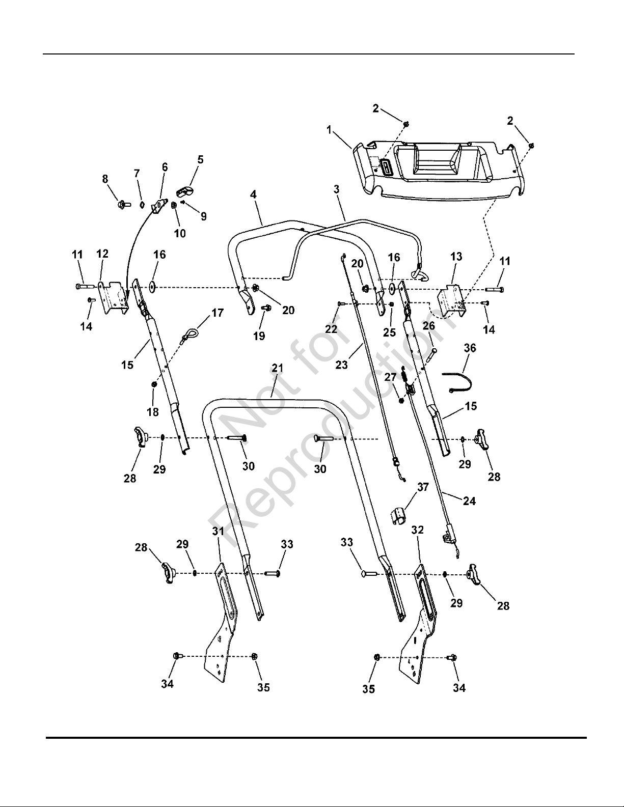
Handles and Controls
p
Not for
Reproduction
Part No Descri
1 7101068 1 PANEL, Upper Handle, Snapper 21 WBM
2 1960382 2 RIVET, Pop .250 Dia.
3 7100844A 1 BAIL, Pivot Handle
4 7300434A 1 HANDLE, Pivot
5 7023655 1 LEVER, Lock Handle
6 7300526A 1 HANDLE, Lock
7 7026257 1 WASHER, .531 x .781 Wave
8 1716654 1 BOLT, 5/16-18 Shoulder
9 7071921 1 RIVET, Plastic Snap
10 7091601 5 NUT, 5/16-18 Flange Lock, YZ
11 7090669 2 SCREW, 5/16-18 x 1-3/4” Hex Head Cap, GR 5
12 7300792A 1 BRACKET, Rotation Limit, RH
13 7300436A 1 BRACKET, Rotatio n Li mit, LH
14 7900067 2 SCREW, 1/4-20 x .55 Torx Self-Tap
15 7300459A 2 HANDLE, Upper, Straight, 22”
16 7023649 2 WASHER, 5/16 Nylon
17 7028488 1 R OPE GUID E, (1/4-20 thread)
18 7076978 1 NUT, 1/4-20 Hex Nyloc
19 7090361 1 SCREW, 5/16-18 x 5/8” Hex Washer Self-Tap
20 7090951 4 NUT, 5/16-18 Large Head Center Lock, Black
21 7301013A 1 HANDLE, Lower
22 7091085 1 BOLT, #10-24 x 1/2” Flat Head Square Neck
23 7102666 1 CABLE, OPC, 22”, Pivot Handle
24 7102665 1 CABLE, Drive, 22”, Pivot Handle
25 7091290 1 NUT, #10-24 Hex Nyloc
26 7090505 2 SCREW, 1/4-20 x 2”, Hex Head Cap, GR 5
27 7090372 1 NU T, 1/4-2 0 Hex Center Lock
28 7035744 4 KNOB, 5/16-18 Wing (Black)
29 7090391 4 WASHER, 5/16” Internal Tooth Lock
30 7091189 2 BOLT, 5/16-18 x 2” Curved Head Square Neck, GR 2
31 7300669A 1 BRACKET, Lower Han d l e LH 22 ” WB M
32 7300668A 1 BRACKET, Lower Handle, RH 22” WBM
33 7091612 2 BOLT, 5/16-18 x 1-1/2” Round Head Square Neck
34 7091811 2 BOLT, 5/16-18 x 5/8” Hex Flange Lock, YZ
35 7091601 2 NUT, 5/16-18 Flange Lock, YZ
36 7024649 1 WIRE TIE, 11 Inch Standard Black Nylon
37 721768 2 CLIP, Cable, Double
tionItem Qty
Footnotes:
Manual No. 700648622" STEEL DECK REAR DISCHARGE
5
Page 6

Deck Assembly
Not for
Reproduction
Manual No. 7006486 22" STEEL DECK REAR DISCHARGE
6
Page 7

Deck Assembly
p
Not for
Reproduction
Part No Descri
1 7300400D 1 DECK, 22” Walk, 3-N-1
2 7900067 3 SCREW, 1/4-20 x 11/16” Pan Head Self-Tap (Torx) or 722848
3 7091020 4 PUSHNUT, 1/4”
4 7300855D 1 BRACKET , Chute
5 7300856D 1 PLATE, Mulch, 22” RB Scott's
6 722507 1 SPRING, Chut e (Torsion)
7 7101067 1 ROD, Pivot (1/4” Dia. x 5.55”)
8 721682 1 COVER, Mulch, Plastic, Black
9 721681 1 SIDE CHUTE, Plastic, Black
10 7103347 1 GUARD, Rear
11 7091286 4 SCREW, #10-24 x 1/2” Hex Washer Self-Tap (Sems)
12 7091619 10 NUT, 3/8-16 Hex Flange Lock, YZ
13 7501055 1 ASSEMBLY, Height-Of-Cut, Left Rear, 22” WBM
14 7501056 1 ASSEMBLY, Height-Of-Cut, Right Rear, 22” WBM
15 7501058 1 ASSEMBLY, HOC, Left Front, 22” WBM, Propelled
16 7501057 1 ASSEMBLY, HOC, Right Front, 22” WBM, Propelled
17 7100633 4 GRIP, Height Latch
18 7500540 2 ASSEMBLY, Wheel & Bearing, 8 x 2 Idle, DW Tread incl. two 1-1/8” O.D. Flanged Ball Bearings
(p/n 7101380)
19 7500542 2 ASSEMBLY, Dri ve Wheel & Bearing, 8 x 2, DW Tread incl. two 1-1/8” O.D. Flanged Ball
Bearings (p/n 7101380)
20 722604 4 WASHER, 1” O.D. x .387 I.D. Flat
21 7091585 4 NUT, 3/8-16 Hex Center Lock, YZ
22 7101350 4 HUBCAP, Black
23 7300440D 1 BAFFLE, Front, 22” WBM
24 7101243 1 DOOR, 22” Rear
25 7101070 1 ROD, Pivot, Rear Door (1/4” Dia. X 17-1/2”)
26 7101461 1 SPRING, Torsion, Rear Door, 22” WBM
27 7300668A 1 BRACKET, Lower Handle, RH 22” WBM
28 7300669A 1 BR A C K E T, Lower Handle LH 22” W B M
29 7091811 2 BO LT, 5/16-18 x 5/8” Hex Flange Lock, YZ
30 7091601 3 NUT, 5/16-18 Flange Lock, YZ
31 7014341 4 RING , External Retaining (Waldes 5133-50)
32 7101207 2 GEAR, Pinion, 22” WBM, Front Wheel Drive
33 7101402 2 DUST SHIELD, Forward, 22” WBM
34 7900054 4 SCREW, 3/8-16 x 3/4” Hex Head Cap, GR 5, YZ
35 7100857 1 TRANSMISSION, Rocker 22” WBM, VS
36 7101270 2 DRIVE PIN, 22” WB M, Front Wheel Drive
37 7300854D 1 BAFFLE, Rear, 22” Deck
tionItem Qty
Footnotes:
Manual No. 700648622" STEEL DECK REAR DISCHARGE
7
Page 8

Engine, Blade & Grass Bag
Not for
Reproduction
Manual No. 7006486 22" STEEL DECK REAR DISCHARGE
8
Page 9

Engine, Blade & Grass Bag
p
Not for
Reproduction
Part No Descri
1 720351 1 BOLT, 3/8-16 NS x 2-1/2”
2 7101449 1 ASSEMBLY, Engine Spacer, 22” WBM, Self-Propelled includes 7101209 (spacer) & 7101448
(3) (bushings)
3 7101195 1 FRONT COVER, Deck, 22” Front Wheel Drive
4 7900018 2 SCREW, 4.8 x 1. 59 x 13mm, Round Washer Head Hi-Lo (Torx)
5 7101302 2 SPACER, Belt Guide 22”
6 7101024 2 BELT GUIDE, Engine, 22”
7 7101451 2 SCREW, 3/8-16 x 3” Hex Washer Self-Tap
8 7100437 1 PULLEY, Engine
9 7092086 1 SET SCREW, 5/16-18 x 1/2” Hex Recess
10 7091214 1 KEY, #HP-506 HI-PRO
11 7100913 1 ** BELT, Drive (3L Section; 31.94” effective length)
12 7100740 1 BLADE HUB, 22” Deck, Self Propelled
13 7100851 1 BLADE, 22”, Walk Mower
14 721890 1 WASHER, .38” I.D. x 1.183 O.D. Bellville
15 720209 1 BOLT, 3/8-24 x 3-1/4” Hex Head, GR 8
16 7101230A 1 BAG FRAME, 22” WBM (weldment)
17 7102573 1 GRASS BAG, 22” Rear Discharge
18 7026421 1 GRIP, Rectangular (Black)
19 124T02-0650-B3 1 * ENGINE, B&S, 650 Ser, X-Spec used on 7800440
19 124L02-4650-F3 1 * ENGINE, B&S, 650 Ser, X-Spec used on 7800447
19 126T02-0675-B3 1 * ENGINE, B&S, 675 Ser, X-Spec used on 7800606
19 126L02-4675-F3 1 * ENGINE, B&S, 675 Ser, X-Spec used on 7800609
tionItem Qty
Footnotes:
NOTE: * Purchase engine parts from engine manufacturer dealer.
Note: ** Part number appears on belt
9
Manual No. 700648622" STEEL DECK REAR DISCHARGE
Page 10

Transmission (22")
Not for
Reproduction
Manual No. 7006486 22" STEEL DECK REAR DISCHARGE
10
Page 11

Transmission (22")
p
Not for
Reproduction
Part No Descri
1 7100857 1 TRANSMISSION, Rocker 22” WBM, VS
2 7900032 8 SCREW, 7mm x 1 x .550 AB Point
3 7100913 1 ** BELT, Drive (3L Section; 31.94” effective length)
4 7101009 1 BELT GUIDE, Transmission, 22” WBM
5 7900055 2 SCREW, #10-14 x 1/2” Hex Washer Self-Tap or 7091195 (SCREW, #16-16 x 3/4” Pan Head
Self-Tap, Combo)
tionItem Qty
Footnotes:
Note: ** Part number appears on belt
Manual No. 700648622" STEEL DECK REAR DISCHARGE
11
Page 12

Decals
Not for
Reproduction
Manual No. 7006486 22" STEEL DECK REAR DISCHARGE
12
Page 13

Decals
p
Not for
Reproduction
Part No Descri
1 7101538 1 DECAL, Front Cover, 22” Snapper, FWD
2 7102862 1 DECAL, Pivot-N-Go
3 7102153 1 DECAL, Briggs Engine, 675 Series
4 7102697 1 DECAL, Pivot Handle, Snapper
5 7101547 1 DECAL, Neutral Lock
6 7029782 1 DECAL, OPC Bail International Symbol
7 7102152 1 DECAL, Briggs Engine, 650 Series
8 7102151 1 DECAL, Briggs Engine, 675 Series
9 7102746 1 DECAL, Spark Arrestor
10 7101394 1 DECAL, Warning, Rear Discharge Door
11 7013010 1 DECAL, Danger, Cut Finger
tionItem Qty
Footnotes:
Manual No. 700648622" STEEL DECK REAR DISCHARGE
13
Page 14

Not for
Reproduction
Page 15

Hardware Identification & Torque Specifications
No
Marks
0
1/4 3/4
1/2
21
1/4 3/4
1/2
1/4 3/4
1/2
1/4 3/4
1/2
4
Not for
Reproduction
Torque Specification Chart
FOR STANDARD METRIC MACHINE HARDWARE (Tolerance ± 20%)
Property
Class
Size Of
Hardware
M3
M4
M5
M6 7.3 10.3 12.1
M7 12.1 16.9 19.9
M8 17.7
M10 35 50
M12 61 86.2 103 140
M14
M16 147 210 250 340
M18 202 287 346 470
M20 290 405 486 660
M22 390 559 656 890
M24 497
M27 733 1032 1239 1680
M30 995 1401 1681 2280
M33
M36 1740 2441
M39 2249 3163
The guides and ruler furnished below are designed to
help you select the appropriate hardware.
010
Nut, M8
Thread
Diameter (mm)
Inside
Diameter (in)
Nut, 1/2-16
Class 5.6
in/lbs
ft/lbs
5.88
13.44
26.4
44.64
5.2
7.7
15
26
42
64
89
126
169
217
320
435
590
759
988
20
5.6
Nm. Nm. Nm.
.56
1.28
2.50
4.3
7.1
10.5
21
36
58
88
121
171
230
295
435
590
800
1030
1340
30
8.8
Class 8.8
in/lbs
ft/lbs
13.44 1.80
30.72 43.44 52.56
60.96
Class 10.9
in/lbs
ft/lbs
19.2 22.92
1.28
2.90
5.97 7.15
5.75
9.9
16.5
24
48
83
101
136 162 220
132
200
275
390
530
708
375
995
1350
1349
1902 2278 3090
1830
2360
3050
50
60
Body Length
40
Screw, M8- 1.25 x 25
Thread
Diameter (mm)
Threads
per inch
Body
Diameter
Screw, 1/2- 16 x 2
10.9
4.10
8.10
14
23
25
34
67
117
185
285
390
550
745
960
1400
1900
2580
3310
4290
80
Diameter
Distance between
threads (mm)
Threads
per inch
3
12.9
Class 12.9
in/lbs
ft/lbs
29
59
840 1140
2935 3980
3798
Body
Nm.
2.15
4.95
9.7
16.5
27
40
81
5150
90 10070
Body
Length (mm)
Body
Length (in)
Torque Specification Chart
FOR STANDARD MACHINE HARDWARE (Tolerance ± 20%)
Hardware
Grade
Size Of
Hardware ft/lbs Nm. ft/lbs Nm. ft/lbs Nm.
8-32
8-36
10-24
10-32
1/4-20
1/4-28
5/16-18 11 15.0 17 23.1 25 34.0
5/16-24 12 16.3 19 25.8 29 34.0
3/8-16 20 27.2 30 40.8 45 61.2
3/8-24 23 31.3 35 47.6 50 68.0
7/16-14 30 40.8 50 68.0 70 95.2
7/16-20 35 47.6 55 74.8 80 108.8
1/2-13 50 68.0 75 102.0 110 149.6
1/2-20 55 74.8 90 122.4 120 163.2
9/16-12 65 88.4 110 149.6 150 204.0
9/16-18 75 102.0 120 163.2 170 231.2
5/8-11 90 122.4 150 204.0 220 299.2
5/8-18 100 136 180 244.8 240 326.4
3/4-10 160 217.6 260 353.6 386 525.0
3/4-16 180 244.8 300 408.0 420 571.2
7/8-9 140 190.4 400 544.0 600 816.0
7/8-14 155 210.8 440 598.4 660 897.6
1-8 220 299.2 580 788.8 900 1,244.0
1-12 240 326.4 640 870.4 1,000 1,360.0
1. These torque values are to be used for all hardware
excluding: locknuts, self-tapping screws, thread forming
screws, sheet metal screws and socket head setscrews.
2. Recommended seating torque values for locknuts:
a. for prevailing torque locknuts - use 65% of grade 5
b. for flange whizlock nuts and screws - use 135% of
3. Unless otherwise noted on assembly drawings, all torque
values must meet this specification.
Common Hardware Types
Hex Head Capscrew
SAE Grade 2 SAE Grade 5 SAE Grade 8
in/lbs in/lbs
19
2.1
20
2.3
27
3.1
31
3.5
66
7.6 8 10.9 12 16.3
76
8.6 10 13.6 14 19.0
30
31
43
49
in/lbs
3.4
3.5
4.9
5.5
NOTES
torques.
grade 5 torques.
41
43
60
68
Washer
4.6
4.9
6.8
7.7
Standard Hardware Sizing
When a washer or nut is identified as 1/2” (M8), this is
Nominal size
the
, meaning the
inside diameter
is 1/2 inch
(8mm metric thread diameter); if a second number is present
it represents the
threads per inch
(distance between threads).
When bolt or capscrew is identified as 1/2 - 16 x 2” (M8 - 1.25 x 50 ),
this means the
Nominal size
metric thread diameter), the second number,16, represents the
threads per inch, (1.25 thread diameter).
body length of the bolt or screw, 2 inches (50mm).
, or body diameter is 1/2 inch (8mm
The final number is the
Carriage Bolt
Wrench & Fastener Size Guide
1/4” Bolt or Nut
Wrench—7/16”
M6 Bolt or Nut
Wrench—10mm
5/16” Bolt or Nut
Wrench—1/2”
M8 Bolt or Nut
Wrench—13mm
3/8” Bolt or Nut
Wrench—9/16”
M10 Bolt or Nut
Wrench—17mm
7/16” Bolt or Nut
Wrench (Bolt)—5/8”
Wrench (Nut)—11/16”
M12 Bolt or Nut
Wrench—19mm
Lockwasher
Hex Nut
1/2” Bolt or Nut
Wrench—3/4”
M14 Bolt or Nut
Wrench—22 mm
Page 16

Parts Manual fo
r
Not for
Reproduction
22" STEEL DECK REAR DISCHARGE
VARIABLE SPEED WALK BEHIND MOWE
IT IS THE POLICY OF BRIGGS & STRATTON CORP TO IMPROVE ITS
PRODUCTS WHENEVER IT IS POSSIBLE AND PRACTICAL TO DO SO.
WE RESERVE THE RIGHT TO MAKE CHANGES OR ADD
IMPROVEMENTS AT ANY TIME WITHOUT INCURRING ANY
OBLIGATION TO MAKE SUCH CHANGES ON PRODUCTS
Briggs & Stratton Yard Power Products Group
535 Macon Road
McDonough, GA, 30253 U.S.A.
800-935-2967
www.snapper.com
Copyright ©2010
Milwaukee, WI USA. All Rights Reserved
Briggs & Stratton Corporation
Manual No. 7006486
Revision: B 2/9/2010
 Loading...