

Page 1
SET-UP INSTRUCTIONS & PRE-OPERATION CHECKLIST
AS SHOWN
CABLE
For SNAPPER “W” SERIES REAR ENGINE RIDERS
INTRODUCTION: The SNAPPER “W” Series Rear Engine Riders are shipped fully assembled and require
minimal set-up. Complete each of the following steps carefully. Review and complete each item as instructed
on the Pre-Operation checklist. The Snapper Product Registration card must be filled out and sent to Customer
Service department at Snapper when completed.
BATTERY ACTIVATION and INSTALLATION
Snapper riders with a model prefix “ W ” are supplied with
wet batteries and do not require the addition of
electrolyte. All batteries require a slow charge before
being placed into service.
1. BATTERY REMOVAL
A. Remove battery cover by pulling each side away
from ratchet fasteners. See Figure 1.
B. Remove the hair pin and swivel f rom the deck
support to allow clearance for battery removal.
C. Remove battery from battery compartment.
PULL COVER AWAY
FROM RATCHET
FASTENERS ON
BOTH SIDES
FIGURE 1
2. BATTERY CHARGING
A. With all cell caps removed, connect an
automotive type battery charger to battery
terminals; RED to positive (+) and BLACK to
negative (-) terminal.
B. Slow charge at 2 to 6 amps for 30 minutes.
C. After charging, check level of electrolyte, add
water only if necessary, and tighten cell caps.
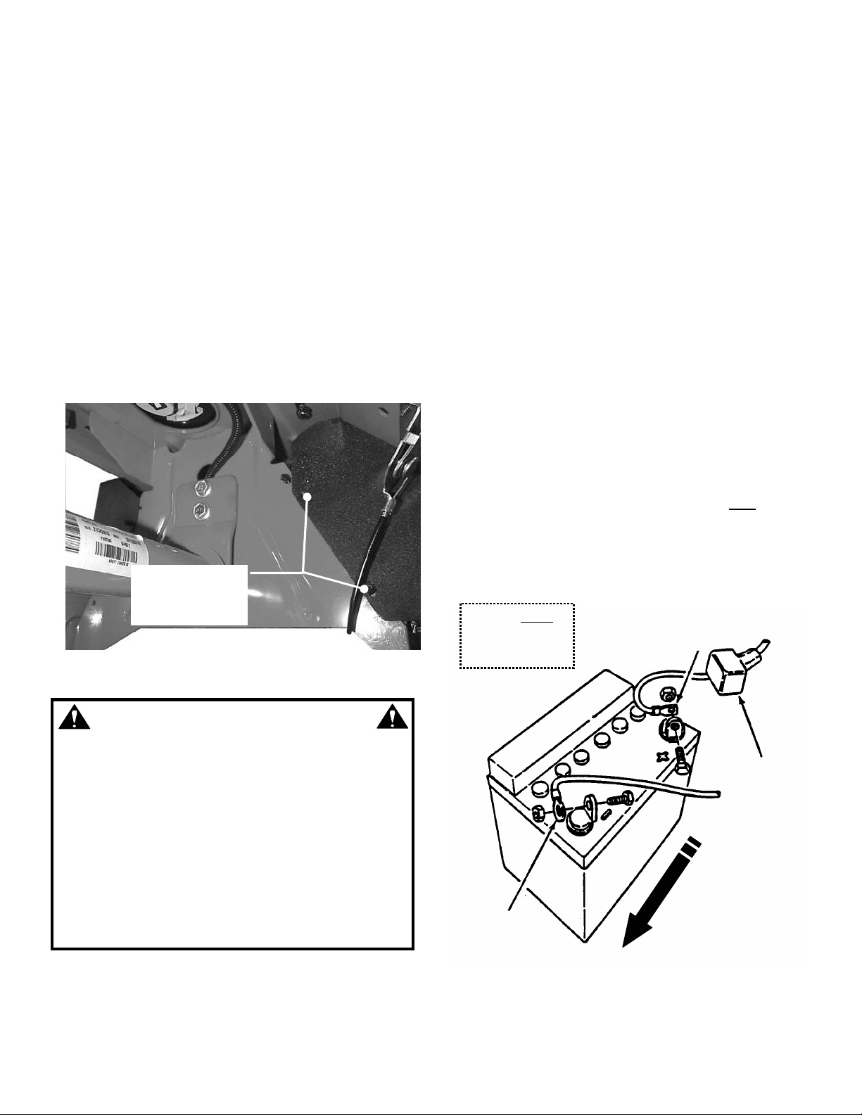
3. BATTERY INSTALLATION
A. Slide battery partially into box, with positive end to
inside and terminals to rear, to allow for cable
installations.
B. Battery cables MUST BE SECURED TO
BATTERY TERMINALS as shown in Figure 2,
using the 1/4” screws, that are mounted on
terminals, and lock nuts from the hardware bag.
C. Install positive (+) cable first. Place the positive
(+) terminal insulator over positive terminal and
cable. Install negative (-) cable last after
terminal insulator has been installed.
See Figure 2.
D. Slide battery into battery box and reinstall battery
cover.
E. Reinstall deck support swivel and hair pin.
CABLES MUST
BE MOUNTED
TO TERMINALS
RED POSITIVE (+)
positive
WARNING
The electrolyte (acid) produces a high ly explosive gas.
Keep all sparks, flame and fire away from area when
charging battery or when handling electrolyte or
battery. Electrolyte (acid) is a highly corrosive liquid.
Wear eye protection. Wash affected areas immed iately
after having eye or skin contact w ith electrolyte (acid).
Battery acid is corrosive. Rinse empty acid containers
with water and mutilate before discarding. If acid is
spilled on battery, bench, or clothing, etc., Flush with
clear water and neutralize with baking soda. DO NOT
attempt to charge battery while installed on the RIDER.
DO NOT use “BOOST” chargers on the battery. DO
NOT OVER FILL!
POSITIVE
TERMINAL
INSULATOR
TO OUTSIDE OF
MOWER
BLACK
NEGATIVE (-)
CABLE
FIGURE 2
INSTRUCTION No. 7-5122 (I.R. 6/28/02)
1
Page 2
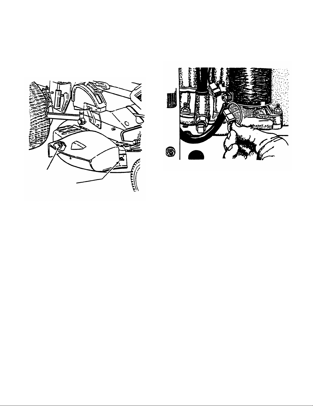
DISCHARGE DEFLECTOR
The discharge deflector is shipped in the “UP” position.
Remove rubber band, lower discharge deflector and
secure to deck with carr iage bolt(s), flat washer(s) and
wing nut(s) furnished in the deck. See Figure 3.
ELECTRICAL CIRCUIT
The electrical connection at the engine is shipped
disconnected to protect the electrical system when the
battery is installed and MUST BE THE LAST STEP in
preparation.
A. Connect electrical circ uit at rear of the engine.
See Figure 4.
SECURE DISCHARGE
DEFLECTOR TO DECK
WITH CARRIAGE BOLTS,
FLAT WASHERS, AND
WING NUTS
FIGURE 3
FIGURE 4
LUBRICATION and FUEL
1. Engine
A. Perform normal engine service, oil and fuel,
according to engine manuf acturer’s recomm endations
found in the Engine Owner’s Manual.
PRE-OPERATION CHECKLIST
Complete all items on the Pre-Operation Checklist as
instructed.
2
Page 3

SERVICE NOTES
______________________________________________________________________________
______________________________________________________________________________
______________________________________________________________________________
______________________________________________________________________________
______________________________________________________________________________
______________________________________________________________________________
______________________________________________________________________________
______________________________________________________________________________
______________________________________________________________________________
______________________________________________________________________________
______________________________________________________________________________
______________________________________________________________________________
______________________________________________________________________________
______________________________________________________________________________
______________________________________________________________________________
______________________________________________________________________________
______________________________________________________________________________
______________________________________________________________________________
______________________________________________________________________________
______________________________________________________________________________
______________________________________________________________________________
______________________________________________________________________________
______________________________________________________________________________
______________________________________________________________________________
______________________________________________________________________________
______________________________________________________________________________
______________________________________________________________________________
______________________________________________________________________________
______________________________________________________________________________
______________________________________________________________________________
______________________________________________________________________________
______________________________________________________________________________
______________________________________________________________________________
______________________________________________________________________________
______________________________________________________________________________
______________________________________________________________________________
______________________________________________________________________________
______________________________________________________________________________
______________________________________________________________________________
______________________________________________________________________________
______________________________________________________________________________
______________________________________________________________________________
______________________________________________________________________________
______________________________________________________________________________
______________________________________________________________________________
______________________________________________________________________________
______________________________________________________________________________
______________________________________________________________________________
______________________________________________________________________________
______________________________________________________________________________
3
Page 4

PRE-OPERATION CHECKLIST
Snapper has completed initial adjustments and performed operational tests prior to shipping the machine. Due
to the possible effects of shipping, handling and storage, Snapper intends for all of the following items to be
verified and necessary final adjustments made at time of setup. It remains good practice and is strongly
recommended that all the items also be checked prior to placing the machine into service. It is very important
that setup is verified and all o perational t ests complet ed and result s are acceptable. After completing t his form,
sign and retain for future reference.
SET-UP CHECKLIST
_____ STEERING WHEEL and steering shaft assembled.
_____ TIE RODS connected.
_____ LUBRICATION of entire unit completed.
_____ OPERATOR’S SEAT installed and tightened and seat switch connected.
_____ FUEL TANK installed and fuel line connected.
_____ GRASS DEFLECTOR, MULCH COVER or CATCHER ADAPTER and assembly positioned, secured, checked.
_____ BATTERY activated and charged per instructions and installed into battery compartment on machine.
_____ TIRE inflated to proper Pounds per Square Inch (PSI). Front tire is 12 PSI and Rear tire is 12 PSI.
CUTTING BLADE & MOWER
_____ BLADE RETAINING hardware checked for proper tightness.
_____ BLADE TIP CLEARANCE inside lower edge of mower checked and corrected as needed.
_____ BLADE STRAIGHTNESS checked and adjusted as required.
_____ MOWER CUTTING HEIGHT settings checked and adjusted as needed (with tires properly inflated).
_____ MOWER SIDE TO SIDE level checked and adjusted as needed (with tires properly inflated).
_____ MOWER FRONT TO REAR setting checked and adjusted as needed (with tires properly inflated).
_____ BLADE LEVER checked and adjusted as required.
_____ BELT TENSION checked and adjusted as required.
_____ REVERSE LOCKOUT MECHANISM shifter will not go into reverse when blade pedals are depressed.
PRE-START CHECKS & SERVICES
_____ TIRES checked and inflated to correct pressures.
_____ ENGINE OIL level checked.
_____ DIFFERENTIAL check lubricant and add as needed.
_____ CHAIN CASE check lubricant and add as needed.
_____ YOKE ASSEMBLY checked for freedom of movement.
_____ FUEL added to tank and system checked for leaks. Refer to Engine’s Owner’s Manual for fuel specifications.
_____ BATTERY (not overfilled!) reinstalled and properly connected with red boot over positive terminal.
OPERATIONAL TESTS
_____ CHECK SEAT SWITCH for proper function
_____ INTERLOCK SYSTEMS checked to insure proper functioning.
_____ ENGINE STARTED and throttle control settings checked.
_____ IGNITION SWITCH checked to insure engine stops when turned to OFF position.
_____ PARKING BRAKE tested to insure proper operation.
_____ CLUTCH/BRAKE tested for proper operation and adjusted as required.
_____ BLADE STOPS in 3 seconds or less after releasing the blade pedal. Adjust blade brake as required.
_____ BLADE LEVER can be moved to OFF position with blade pedal depressed.
CONSUMER INFORMATION
SALE DATE
Retailer's Name
Address_________________________ City
MACHINE WILL BE USED COMMERCIALLY? YES _________ NO
Purchaser's Name
Address_________________________ City
IMPORTANT: This form is to be retained for future reference regarding Warranty, proof of purchase, traceability for product
recall or service, etc. Complete the Product Registration Card immediately and mail to: Customer Service Department at
SNAPPER, P.O. BOX 1379, McDonough, Georgia, 30253.
MACHINE MODEL SERIAL NO.
Signature
State Zip
Signature
State Zip
INSTRUCTION No. 7-5122 (I.R. 6/28/02)
4
 Loading...