

Page 1
#6-3317 SINGLE BAG GRASS CATCHER for SNAPPER
REAR ENGINE RIDERS with 28/33” DECKS & LAWN TRACTORS with 33” DECKS
This grass catcher kit fits Lawn Tractors with 33” Decks and Rear Engine Riders w ith 28” & 33” Decks. On
Series “A” & Later Lawn Tractors, Adapter Kit #6-1334 must be installed before this grass catcher can be
installed. On Series “0-2” Lawn Tractors, Adapter Kit #6-1068 must be installed before this grass catcher can
be installed. Install adapter kit as described by instructions provided with kit.
WARNING
DO NOT attempt any maintenance, adjustments,
service, or repairs with engine running. STOP
engine. STOP blade. Set park brake. Remove key.
Remove spark plug wire and secure away from
spark plug. Engine and components are HOT. Avoid
burns, allow sufficient time to cool.
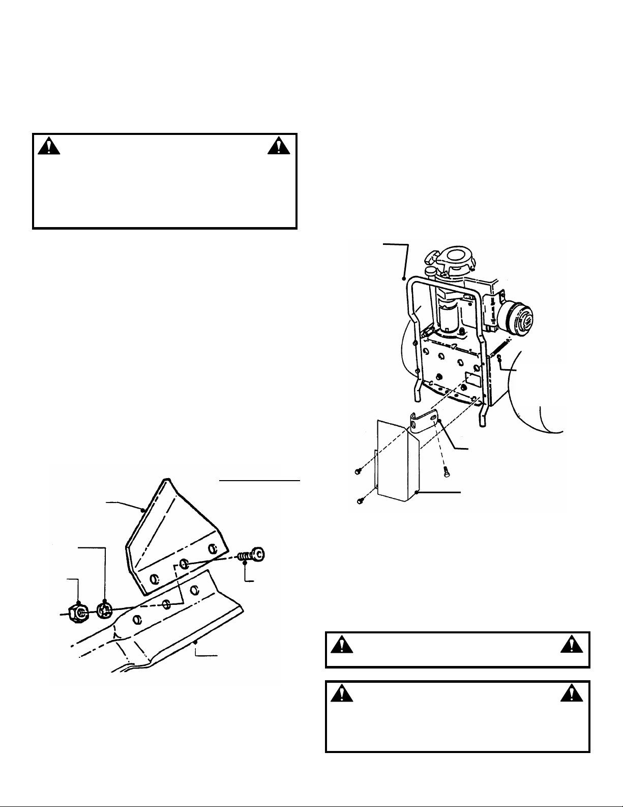
STEP 1: AIR LIFT INSTALLATION.
An optional Air Lift Kit 6-1777 has been included with
this grass catcher and may be installed to enhance
bagging performance in certain conditions. The air lifts
can be installed by reaching through the discharge
opening or by removing the blade. Attach one air lift to
each end of the blade using the hardware and
instructions provided in the kit. Be certain to install lifts
on both ends of blade. Torque nuts and bolts on air lifts
to 20 to 30 ft. lbs. Torque blade retaining hardware to 45
to 55 ft. lbs. See Figure 1.
NOTE: Not all original equipment or accessory blades
will accept the Air Lift Kit. Contact an authorized dealer if
you have questions.
#6-1777 AIR LIFT KIT
28” & 33” DECKS
AIR LIFT
LOCK
WASHER
HEX
NUT
SCREW
(USED ON REAR ENGINE RIDERS ONLY)
Remove both screws from right side of bumper. Remove
bolt from right side of main case. Position the muffler
shield so that the holes line up with the holes on the
bumper. Position the bumper reinforcement with top hole
of bumper. Reinstall screws and tighten securely. Install
bolt into bumper reinforcement and tighten securely into
side of main case. See Figure 2.
BUMPER
INSTALL BUMPER
REINFORCEMENT
BOLT INTO SIDE OF
MAIN CASE
BUMPER
REINFORCEMENT
MUFFLER SHIELD
FIGURE 2
STEP 3: HANDLE TO TUBE MOUNTING
Position the tube handle base inside the grass tube.
Place the tube handle on the outside,
align the holes
then secure base and handle with two 1/4-20 X 3/4”
carriage bolts (heads on inside of tube) 1/4” lock
washers and 1/4-20 hex nuts on the outside and tighten
securely. See Figure 3.
BLADE
FIGURE 1
INSTRUCTION NO. 7-5437 (I.R. 1/29/03)
STEP 2: MUFFLER SHIELD
WARNING
To prevent fires, keep muffler area clear of debris.
WARNING
The cutting blades and the edges of the cutting deck
are extremely sharp and can cause severe injury.
Always wear heavy leather gloves when working
around cutting blades and the cutting deck.
1
Page 2
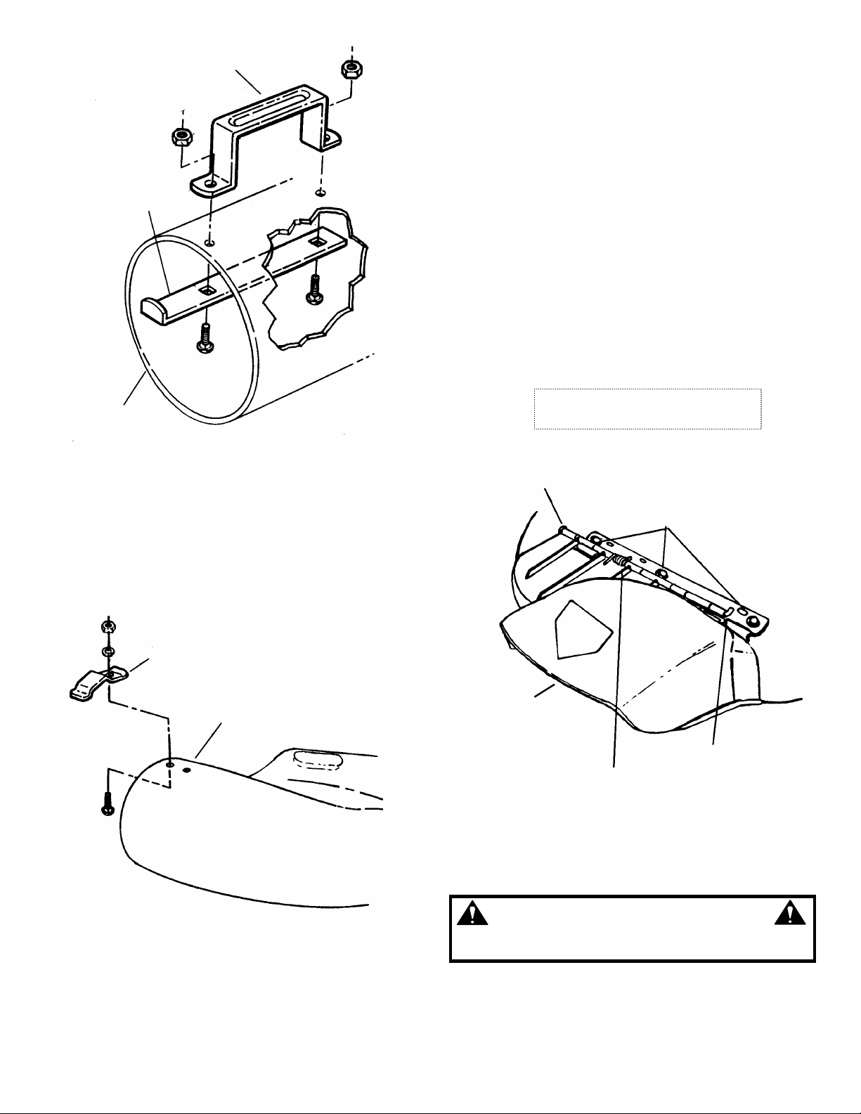
TUBE HANDLE
TUBE HANDLE
BASE
GRASS
TUBE
FIGURE 3
STEP 4: TUBE LATCH TO ADAPTER MOUNTING
Position tube latch onto chute adapter. Insert one of the
1/4-20 X 3/4” carriage bolts (heads on inside of tube)
into the hole on the end of the adapter. Secure with 1/4”
lock washer and 1/4-20 hex nut. See Figure 4.
NOTE: If mulching cover is installed on deck it must
be removed before going to step 5. (Also change
from mulching blade to regular blade.)
STEP 5: ADAPTER TO DECK MOUNTING
Loosen the three hex head deflector hinge screws.
Remove the side deflector bolts & wing nut and store for
future use. See Figure 5A. For riders, lift the deflector.
For tractors, remove palnut, hinge pin, hinge spring &
deflector; save for future use. See Figure 5A. Pos iti on th e
adapter over deck opening, forward of engagement lugs.
See Figure 5B. Slide adapter toward the rear until the
retaining ridges slide under the two engagement lugs on
the deflector latch hinges. See Figure 5C. Bump the
adapter rearward with the palm of your hand if necessary
to force the ridges under both the front and rear lug
locks. Align the hole in the side of the adapter with the
hole in the deck. Insert the 5/16-18 x 1” long carriage
bolt from inside the deck and secure with a washer &
5/16-18 wing lock nut on the outside. Retighten the three
deflector hinge screws.
DEFLECTOR REMOVED ON
TRACTOR, FLIPPED UP ON RIDER
PALNUT
(REMOVED FOR TRACTOR)
DEFLECTOR
HINGE SCREWS
TUBE LATCH
CHUTE
ADAPTER
DEFLECTOR
(REMOVED FOR
TRACTOR)
BOLT & WING
NUT UNDER
DEFLECTOR
(NOT SHOWN)
HINGE SPRING
(REMOVED FOR
TRACTOR
HINGE PIN
(REMOVED FOR
TRACTOR)
FIGURE 5A
WARNING
FIGURE 4
DO NOT operate machine without entire grass
catcher or guards in place.
2
Page 3
TRACTOR MODEL SHOWN (DEFLECTOR REMOVED)
RETAINING
RIDGES
ENGAGEMENT
LUGS
POSITION ADAPTER
FORWARD OF
ENGAGEMENT LUGS
FIGURE 5B
TRACTOR MODEL SHOWN (DEFLECTOR REMOVED)
ADAPTER
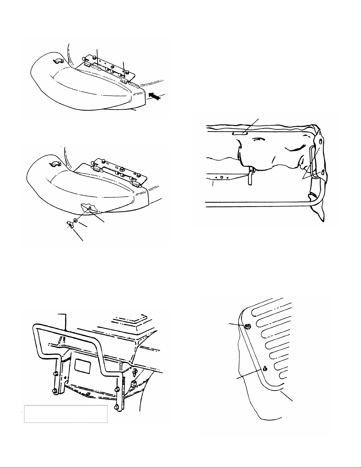
STEP 7: DUST SKIRT TO FRAME INSTALLATION
Punch out or tear out the center portion of the
reinforcement patches (There are two large ovals and
five small round patches) on dust skirt. Insert the legs of
the frame through the two larger holes in the skirt.
Position the five patches over the studs on the frame
(make sure square shield patch on skirt is installed on
muffler side). See Figure 7. Then push the frame down
over the bumpers. NOTE: Skirt should be on outside of
frame and should pass between frame and bumpers.
Insert pins in upper holes in bracket to lock frame in
place. Install clevis pins through holes and secure with
hair pins. Refer to exploded illustration on page 6.
LEGS OF FRAME ARE THROUGH LARGE OVAL SLOTS
POSITION
REAR OF RIDER
SKIRT OVER
STUDS
BOLT
WASHER
WING NUT
FIGURE 5C
STEP 6: Adapter Kit Installation (Tractors only).
Install Adapter Kit #6-1334 per instructions supplied with
kit. See Figure 6.
BUMPER
FIGURE 7
STEP 8: Install the grass catcher latch (item 13) on the
outside of frame using the #10-3/8” long cap screw (Item
14) on outside of frame and with the #10-32 lock nut
(item 15) on the inside. Tighten nuts and screws
securely but still allow the latch to rotate. Refer to
exploded illustration on page 6. Position the container
top over the studs of the frame and secure with the five
5/16” faceted washers. See Figure 8.
FACETED
WASHER
STUD
KIT #6-1334 SHOWN INSTALLED
ON LT LAWN TRACTOR
FIGURE 6
CONTAINER
TOP
FIGURE 8
3
Page 4

STEP 9: Insert the bag rod (item 4, see page 6) into the
upper loop of the grass catcher bag (Item 5, see page 6)
and work the grass bag until completely around the bag
rod. The opening should be positioned at the bag rod
opening. Push the bag rod connector (item 12, see page
6) over one end of the bag rod. Push the bag rod
connector onto the rod until half of the connector is over
the end of the rod. Position bag/rod assembly vertically
and place foot on the inside of the bottom section. Lift
the upper corner of the bag/rod assembly and guide the
other end of the rod into the connector. See Figure 9.
Work the rod ends together until they meet. Slide grass
bag/rod into frame with open mesh to the rear of mower.
Secure in place with latch.
STEP 11: WEIGHT PLATE INSTALLATION (REAR
ENGINE RIDER ONLY)
IMPORTANT: Some model Riders may require the two
mounting holes to be drilled in the front frame. See Step 12
for drilling instructions. The mounting holes in other models
may be covered by the SNAPPER label.
Attach the six weights to the front frame using 3/8-16 x 21/4” hex cap screws, flat washers, 3/8” split lock washers
and 3/8-16 hex nuts. Tighten nuts and bolts securely. See
Figure 11.
BAG ROD
CONNECTOR
FIGURE 9
STEP 10: Slip top end of grass tube into the container
top. Push backward until handle end clears the end of
the chute adapter. Then slide the grass tube over the
adapter opening and turn grass tube until handle base
end catches under the tube latch on adapter. See
Figure 10.
TUBE LATCH
GRASS TUBE
ADAPTER
FIGURE 10
PLACE HEAVY
WASHER ON
BOLT
FIGURE 11
WARNING
Weight Plates must be installed before operating the
machine with a grass catcher kit. Grass catchers
and other attachments affect the handling and
stability of the machine. Use extra care. Refer to the
Operator’s Manual for IMPORTANT SAFETY
INSTRUCTIONS
STEP 12 DRILL MOUNTING HOLES (SERIES M
RIDERS ONLY)
Measure and mark the location of the two holes using
dimensions shown. See Figure 12. Drill two 13/32”
holes. Attach weight plates. Refer to Step 11.
FIGURE 12
4
Page 5

SINGLE BAG GRASS CATCHER KIT ILLUSTRATION
INSTALL LATCH
AS SHOWN
FIGURE 13
5
Page 6

SINGLE BAG GRASS CATCHER KIT ILLUSTRATION
#6-1777 AIR LIFT KIT
28” & 33” DECK
FIGURE 14
6
Page 7

SINGLE BAG GRASS CATCHER KIT PARTS LIST
ITEM PART NO. DESCRIPTION
- 6-1413 KIT, Single Bag Grass Catcher
(Includes Items 1 thru 28)
1 5-3667 TOP, Container (Includes 2-9784 &1-9910 Decals)
2 1-6108 SKIRT, Dust
3 4-7973 FRAME
4 3-7758 ROD, Bag
5 1-9251 BAG, Grass Catcher
6 5-3669 ADAPTER, Catcher (Includes 2-9784 Decal)
7 7-1677 SHIELD, Muffler
8 1-4517 TUBE, Grass
- 6-0313 BAG, Hardware (Includes Items 9 thru 23)
9 3-7745 HANDLE, Tube
10 3-1952 BASE, Tube Handle
11 3-1951 LATCH, Tube
12 1-2556 CONNECTOR, Bag Rod
13 3-1725 LATCH, Grass Catcher
14 9-0532 SCREW, 10-32x1-3/8” Hex Cap
15 9-0376 NUT, #10-32 Hex Lock
16 9-1530 BOLT, 1/4-20 x 3/4” Short Carriage.(3)
17 9-1314 WASHER, 1/4 Internal Tooth Lock (3)
18 9-1576 NUT, 1/4-20 Hex (3)
19 9-1303 BOLT, 5/16-18x1” Short Neck Carriage.
20 9-1537 WING LOCK NUT, 5/16-18
21 2-9840 WASHER, 5/16 faceted (5)
22 2-9841 PIN, Clevis, 5/16 x 1.69 (2)
23 9-1503 PIN, Hair, 3/32 x 1.5 (2)
-- 6-1777 KIT, Air Lift (Includes Items 24 thru 27)
24 3-4468 Lift, Air (2)
25 9-0228 SCREW, 5/16-24 x 5/8” Machine (6)
26 9-0391 WASHER, 5/16 Internal Tooth Lock (6)
27 9-0223 NUT, 5/16-24 Hex (6)
-- 3-1954 REINFORCEMENT, Bumper (Shown in Figure 2)
-- 7-2416 WEIGHT PLATE (SHOWN IN FIGURE 11) (6)
-- 9-1560 BOLT, 3/8-16 x 2 ¼” (SHOWN IN FIGURE 11) (2)
-- 9-1320 WASHER, 3/8 Split Lock (SHOWN IN FIGURE 11) (2)
-- 9-1302 NUT, 3/8 Hex (SHOWN IN FIGURE 11) (2)
-- 2-1746 WASHER, Thick (SHOWN IN FIGURE 11) (2)
7
Page 8

GRASS CATCHER OPERATION
Your Grass Catcher equipped SNAPPER machine will keep your lawn cleaner than it would be by raking or using any
other vacuum method. The Hi-Vac models, which feature a patented rolled-lip deck design, will do an excellent job of
vacuuming and bagging grass clipping, leaves, litter, and even hard to pick-up pine straw. Following are some hints for
using the grass catcher.
• Grass clippings and litter are picked up by the vacuum created by the cutter blade and blown into the bag by the air
blast coming from the blade. The vacuum and air blast must be sufficient to handle the material you want to collect.
• Light, dry clippings may be put into the bag by using the standard cutter blade and mowing at normal speeds.
• Heavier, more lush material will require more suction and air blast. Run engine faster and slow down the forward
speed of the mower.
• Very heavy, lush grass, matted leaves or pine straw will require the entire vacuum and blast you can give it. Run the
engine at top speed and the mower at its slowest forward speed. Take less than a full swath under most severe
conditions.
• For maximum lift, the cutter unit should be set about 2 1/2” to 3” high. The heavier the litter to be picked up, the
higher the unit should be set. Make more than one pass over the area to be cleaned, if needed.
• Normally, it is best to mow or clean by operating in a clockwise direction. However, if litter is matted and heavy,
make the first pass in a counterclockwise direction. As material is picked up on the left side of the cutter unit, it will
more easily enter the chute and go into the bag.
• The vacuum action of the blade will pick up dust unless the grass is very thick or the ground is wet. Be prepared for
this dust storm. You can minimize it if you learn to operate the cutter blade at the lowest speed that will put the
clippings and litter in the bag. Because of the dust, your engine air cleaner should be serviced more frequently than
usual.
• Never fertilize with dry-type fertilizer just before mowing. The vacuum action will pick up most of the fertilizer and put
it in the bag, where it will do very little good for your lawn.
• DO NOT be afraid to experiment with different blade speeds, cutter unit heights, and forward speeds until you have
learned how to make your SNAPPER machine operate best under YOUR conditions.
Some mower operator’s prefer to place a rigid piece of cardboard or plywood in the bottom of the bag for additional
ground clearance and easier handling. If you desire this feature, the dimensions should be 1/8” to 3/8” thick, 15” wide by
35” long with a 4” radius on the corners.
COPYRIGHT © 2003
SNAPPER PRODUCTS INC.
ALL RIGHTS RESERVED
INSTRUCTION NO. 7-5437 (I.R. 1/29/03) Printed in U.S.A.
8
 Loading...