

Page 1

Safety Instructions, Installation & Operator’s Manual For
#6-3131 CLAMSHELL GRASS CATCHER KIT FOR
SNAPPER 33” LAWN TRACTORS,
1999 SERIES “D” & LATER
IMPORTANT!
1999 LAWN TRACTOR SERIAL NUMBER
BEGINS WITH “9” AND TRACTOR MUST BE
EQUIPPED WITH CAST IRON FRONT AXLE.
COPYRIGHT © 2000
SNAPPER INC.
ALL RIGHTS RESERVED
MANUAL No. 7-3409 (I.R. 01/24/00)
Page 2

IMPORTANT SAFETY INSTRUCTIONS
WARNING
All safety instructions and operating instructions in the manuals provided with the Snapper Lawn Tractor and
this Grass Catcher attachment must be followed. Read, understand, and follow ALL instructions and w arnings
in the Operator’s Manual provided with this machine, with the attachment, and ALL instructions and w arnings
on the machine, engine and attachment. Failure to comply with ALL instructions and warnings can result in
damage, serious injury or death to the operator or other persons.
1) DO NOT allow children or others in the yard
when the machine is operated (even with the
blades off).
2) DO NOT allow children or others to ride on the
machine or attachment (even with the blades
off).
3) DO NOT allow children to operate the machine.
4) DO NOT operate blades in reverse. STOP
blades. LOOK and SEE behind and down for
children, pets, and hazards before and while
backing.
5) FRONT WEIGHT (Bumper Kit), provided with
this kit, must be installed before operating
machine with grass catcher.
6) DO NOT operate machine on slopes exceeding
10 degrees (18% grade) when equipped with
grass catcher.
7) Exercise EXTREME CAUTION on all slopes.
Turn blades off when traveling uphill. Use a
slow speed and avoid sudden or sharp turns.
8) DO NOT operate machine across face of slopes.
Operate up and down. Practice on slopes w ith
blades off.
INSTALL CLAMSHELL CATCHER ON 1999 SERIES “D” AND LATER
MODEL LAWN TRACTORS ONLY. LAWN TRACTOR MUST BE
EQUIPPED WITH CAST IRON FRONT AXLE.
! IMPORTANT !
9) AVOID uphill starts. If machine stops going up
hill or tires lose traction, turn blades OFF and
back slowly down the slope.
10) GRASS CATCHER COMPONENTS are subject
to deterioration during normal use. Inspect all
components frequently for signs of wear or
deterioration. Replace worn or damaged
components immediately.
11) DO NOT leave machine with engine running.
STOP engine, STOP blades, SET brake, and
REMOVE key before leaving operator’s position
for any reason.
12) DO NOT attempt to remove or unclog the grass
catcher with engine or blades running. Stop
engine and blades and make sure all rotating
components have come to a complete stop
before removing any catcher component or
attempting to unclog catcher or deck.
13) DO NOT operate machine with Clamshell
Catcher open. The catcher must be closed at all
times, unless dumping. STOP blades before
dumping grass catcher.
2
Page 3

TABLE OF CONTENTS
IMPORTANT SAFETY INSTRUCTIONS..............................................................2
TABLE OF CONTENTS .......................................................................................3
SECTION 1 - ASSEMBLY INSTRUCTIONS.....................................................4-9
Introduction..............................................................................................................................4
Right & Left Bumper Bracket Installation..............................................................................4
Right & Left Bumper Support Installation......................................................................... 4-5
Hitch Plate and Baffle..............................................................................................................5
Hinge Pivot Bolt Installation...................................................................................................6
Hinge Adjustment – Rear Cover......................................................................................... 6-7
LT Front Bumper Kit, #6-3123, Installation............................................................................7
Air Lift Kit, #6-0480, Installation .............................................................................................7
Deck Adapter Installation.................................................................................................... 7-8
Grass Tube Installation....................................................................................................... 8-9
SECTION 2 – OPERATION & MAINTENANCE.................................................10
Introduction............................................................................................................................10
Grass Catcher Operation ......................................................................................................10
Emptying Grass Catcher.......................................................................................................10
If The Grass Catcher Becomes Clogged.............................................................................10
Grass Catcher Maintenance .................................................................................................10
Before Each Use ....................................................................................................................10
Clamshell Assembly Components................................................................................. 11-12
3
Page 4
SECTION 1 – ASSEMBLY INSTRUCTIONS
INTRODUCTION
The #6-3131 Clamshell Grass Catcher kit fits
Snapper Lawn Tractors, 1999 Series “D” and later
models, equipped with 33” decks and Cast Iron
Front Axles. Use the following instructions to
assemble the Grass Catcher components and
prepare your machine for collecting grass clippings
and leaves. Follow and complete each step
carefully.
STEP 2
RIGHT AND LEFT BUMPER SUPPORT INSTALLATION
A. Install Rear Bumper and right Bumper Support to
the right Bumper Bracket. Align holes in Bumper
Support, Bumper and Bumper Bracket. Insert (2)
5/16-18 x 1-3/4” Flange Lock bolts and secure with
(2) 5/16-18 Flange Lock nuts. Do Not tighten at
this time. See Figure 1.2.
WARNING
DO NOT attempt any adjustments, maintenance or
service with the engine running. STOP engine.
STOP blade. Engage parking brake. Remove key.
Remove spark plug wire from spark plug and
secure wire away from spark plug. Engine and
components are HOT. Avoid serious burns, allow
all parts to cool before working on machine.
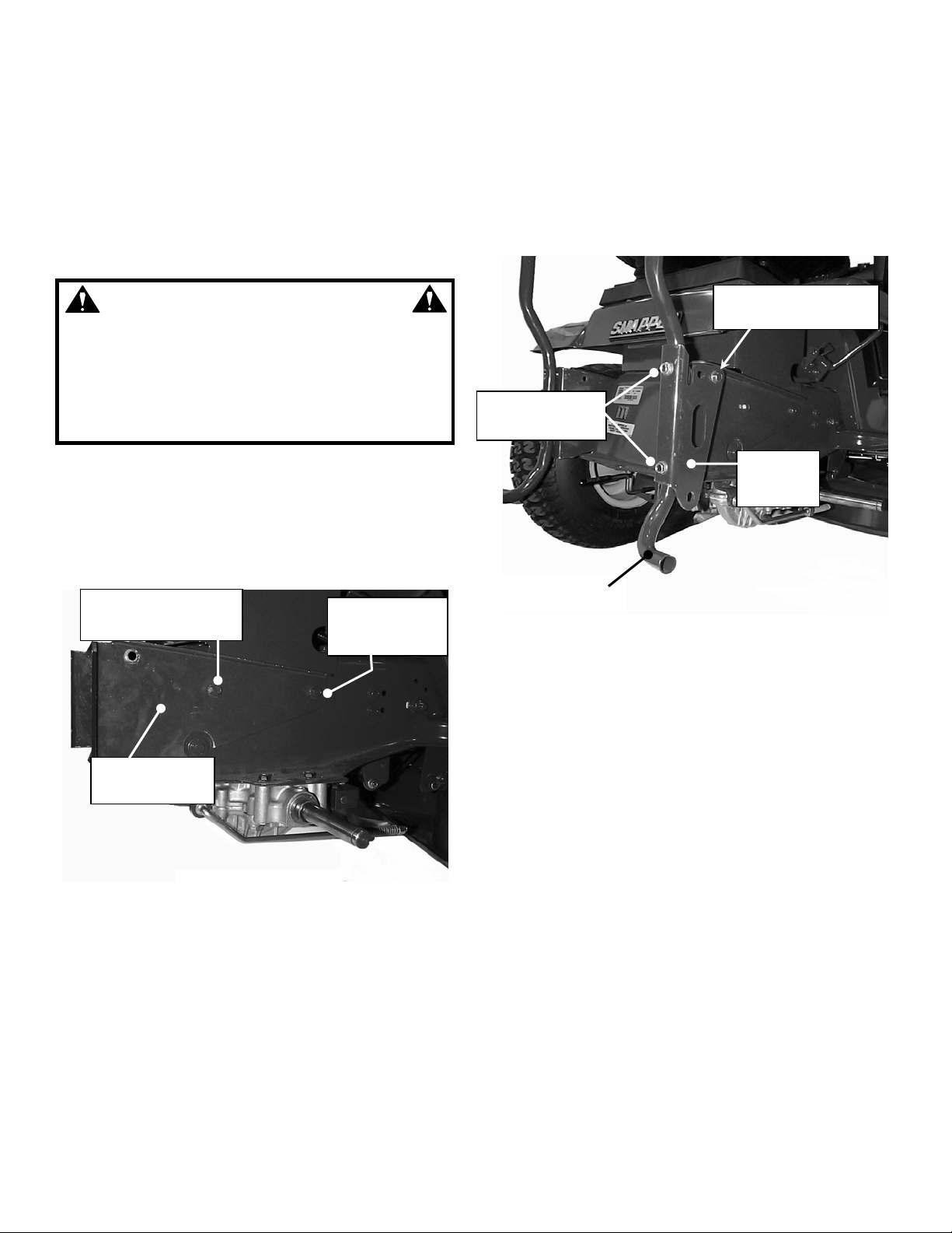
STEP 1
RIGHT AND LEFT BUMPER BRACKET INSTALLATION
A. Remove right rear Seat Support bolt. See Figure
1.1. Note: Removal of rear tires is not required to
complete Bracket installation.
REAR SEAT SUPPORT
BOLT (REMOVE)
RIGHT BUMPER
BRACKET
NOTE: TIRE REMOVED
FOR CLARITY ONLY
FIGURE 1.1
B. Loosen Only – right front Seat Support bolt. Back
bolt out only enough to allow the slotted hole in the
right Bumper Bracket to slip under head of bolt.
C. With front Seat Support bolt in slotted hole, align
rear hole in Bracket and reinstall rear Seat Support
bolt. Tighten bolts securely.
D. Series “F” and Later models Only: Place (1) 5/16-
18 hex nut on each right Seat Support bolt and
tighten securely against inside of frame.
E. Repeat for left Bumper Bracket.
FRONT SEAT
SUPPORT
BOLT
BUMPER BOLTS
5/16-18X1-3/4”
4
SPACER
(HIDDEN IN THIS VIEW)
RIGHT
BUMPER
SUPPOR
REAR BUMPER
FIGURE 1.2
B. Insert Spacer (P/N 7-3272) between right Bumper
Bracket and Bumper Support. Align holes and
insert (1) 5/16-18 x 1-3/4” Flange Lock bolt and
secure with (1) 5/16-18 Flange Lock hex nut. Do
Not tighten at this time. See Figure 1.2.
C. Install left Bumper Support to the left Bumper
Bracket. Align bottom hole in Bumper with hole in
Bumper Bracket. Insert (1) 5/16-18 x 1-3/4” Flange
Lock bolt and secure with (1) 5/16-18 Flange Lock
hex nut. Do not tighten at this time. Align hole in
left Bumper Support with top hole on Rear Bumper
as shown and insert (1) 5/16-18 x 1-3/4” Flange
Lock bolt. Secure with (1) 5/16-18 Flange Lock hex
nut. Do not tighten at this time. See Figure 1.3.
Page 5

SECTION 1 – ASSEMBLY INSTRUCTIONS
B. Place Front Cover Assembly over rear Bumper and
secure in place with spring loaded Latch. See
Figure 1.5.
LEFT
BUMPER
SUPPORT
RIGHT BUMPER
SUPPORT BOLT
REAR BUMPER
LATCH
FIGURE 1.3
D. Align slotted hole in left Bumper Support with hole
in Bumper Bracket and insert (1) 5/16-18 x 1-3/4”
Flange Lock bolt. Tighten (4) Bumper bolts
securely. Place 5/16-18 Flange Lock hex nut on left
Bumper Support bolt and tighten securely. Tighten
right Bumper Support bolt securely. See Figure 1.3.
STEP 3
HITCH PLATE AND BAFFLE
A. Attach triangular shaped Hitch Plate to bottom of
Front Cover Assembly. Orientation of the holes in
the Hitch Plate is important, observe picture
carefully before assembling. Align holes in Hitch
Plate and Front Cover Frame. Insert (2) 5/16-18 x
5/8” Flange Lock hex bolts and secure with (2)
5/16-18 Flange Lock hex nuts. Do not tighten at
this time. See Figure 1.4.
FIGURE 1.5
C. Align hole in Hitch Plate with hole in Bumper
Support. Insert (1) 1/2-13 x 1” hex bolt through
holes with head on inside of Bumper Support.
Place (1) 1/2” Internal Tooth Lock washer and (1)
1/2-13 hex nut on bolt (washer and nut on outside)
and tighten securely. See Figure 1.6.
D. Tighten Hitch Plate bolts that were left loose in
STEP 3, “A”.
E. Attach left end of baffle to Front Cover. Place (1)
3/16” Flat Washer over #10-24 x 3/4” Flange Lock
Bolt and insert from inside cover. Secure with (1)
#10-24 Flange Lock Nut. Tighten nut securely.
BUMPER
SUPPORT
1/2-13 NUT &
1/2” LOCK
WASHER
5/16-18X5/8” FLANGE
LOCK BOLT & 5/16-18
FLANGE LOCK NUTS
FIGURE 1.4
HITCH PLATE
HITCH
PLATE
FIGURE 1.6
5
Page 6

SECTION 1 – ASSEMBLY INSTRUCTIONS
STEP 4
HINGE PIVOT BOLT INSTALLATION
A. Place Rear Cover Assembly on Front Cover
Assembly aligning holes in left Hinge Tabs. Place
one 3/8” flat washer between the two Hinge Tabs
and insert 3/8-16 x 1” hex bolt. See Figure 1.7. Add
3/8” flat washer and secure with 3/8-16 Top Lock
hex nut. Do not over tighten. Hinge must pivot
freely.
B. Repeat on right Hinge Tabs.
HINGE
TAB
FIGURE 1.7
STEP 5
HINGE ADJUSTMENT, REAR COVER
The holes in the rear Hinge Plate are slotted and
adjustment may be required to insure a proper seal
between the front and rear Covers.
A. Insert hook on the right Rear Cover Assembly into
round hole in right Handle Link. Note: Right Handle
Link is flat, no bend. See Figure 1.8.
B. Place one 3/8” flat washer over stud on right of
Handle Tube.
C. Insert stud into center hole of right Handle Link.
Add another 3/8” flat washer over stud and secure
with hair pin. See Figure 1.9. NOTE: The right and
left Handle Links contain 3 closely spaced holes to
adjust the amount of force required to close and
latch the Grass Catcher. To increase the closing
force and provide a tighter seal between the front
and rear covers, place stud in rear hole. To
decrease the force, place stud in front hole.
3/8” FLAT
WASHER
RIGHT
HANDLE
LINK
HOOK
FIGURE 1.8
HANDLE
LINK
HAIR
PIN
FIGURE 1.9
6
Page 7

SECTION 1 – ASSEMBLY INSTRUCTIONS
D. Repeat procedure for left Handle Link.
E. Close catcher by pushing down on Handle.
F. Actuate Catcher Handle. Catcher should open and
close smoothly with no binding. If the action is not
smooth, adjustment to the hinge or handle links
may be required.
PUSH
FIGURE 1.10
G. If hinge adjustment is required, loosen hinge plate
hardware. For a tighter seal, push top of rear cover
frame firmly against the Front Cover Assembly.
Tighten hinge plate hardware securely. See Figure
1.10.
HINGE PLATE
HARDWARE
STEP 7
AIR LIFT KIT, #6-0480, INSTALLATION
Some Lawn Tractor models will not require the
installation of the Air Lift Kit included with the Grass
Catcher. Inspect the blade on your mower. If the blade
does not have mounting holes for the Air Lift Kit, the
blade is a High Lift version and does not require the kit.
If the blade does have the holes in the lift area of the
blade, install the Lift Kit. Installation instructions and the
necessary hardware are included with the Air Lifts.
Blades are extremely sharp and can cause severe
injuries. Wear heavy gloves when working on or
handling blades. DO NOT use blades that show
signs of wear or damage.
DO NOT operate machine without entire Grass
Catcher or guards in place.
STEP 8
DECK ADAPTER INSTALLATION
The Discharge Deflector will have to be removed to
install the Deck Adapter. Be careful to save the
Deflector and all hardware removed for future use when
not bagging.
A. Remove wing nuts, flat washers and bolts securing
Deflector to side of deck. Save hardware. See
Figure 1.11.
WARNING
WARNING
WARNING
The LT Bumper Kit, 6-3123, must be installed before
operating machine with Grass Catcher.
STEP 6
LT FRONT BUMPER KIT, #6-3123, INSTALLATION
The weight of the Clamshell Grass Catcher and
contents affects the stability and handling of the
machine. The Front Bumper Kit must be installed prior
to operating the machine with the catcher installed.
Failure to install the Bumper Kit could cause damage,
serious injury or death. The Bumper Kit, included with
this Grass Catcher Kit, comes with instructions and all
of the hardware required to complete installation.
Follow and complete each step carefully.
WING NUT
& FLAT
WASHER
WING NUT
& FLAT
WASHER
FIGURE 1.11
7
DEFLECTOR
Page 8

SECTION 1 – ASSEMBLY INSTRUCTIONS
B. Remove Hinge nut, Spring, and Hinge Pin. Remove
Deflector. Save for future use. See Figure 1.12.
SPRING
HINGE PIN
ADAPTER
HINGE NUT
FIGURE 1.12
C. Hold the Adapter in front of the deck. Align the
Adapter Lugs with the Lug Retainers in the Hinge.
Push or lightly tap front of Adapter towards the rear
until tight against deck. See Figure 1.13.
LUG RETAINERS
WING NUT &
FLAT WASHER
FIGURE 1.14
D. Attach Tube Latch to Adapter. Insert one 1/4-20 x
3/4” Carriage bolt from inside through upper hole in
Adapter. Place Tube Latch over bolt, followed by
1/4” Internal Tooth lock washer and secure with
1/4-20 hex nut. Align Tube Latch as shown and
tighten securely. See Figure 1.15.
TUBE LATCH
ADAPTER LUGS
FIGURE 1.13
D. Install one of the previously removed bolts into the
hole in the center of the discharge opening and
through the hole in the Adapter. Secure the Adapter
to the deck with a flat washer and wing nut. See
Figure 1.14.
FIGURE 1.15
STEP 9
GRASS TUBE INSTALLATION
A. Attach Tube Handle and Handle Base to Tube
before installing Tube to catcher. Insert (2) 1/4-20 x
3/4” Carriage bolts through Handle Base and holes
in Tube as shown. See Figure 1.16. Place Tube
Handle over bolts followed by 1/4” Internal Tooth
lock washers and secure with (2) 1/4-20 hex nuts.
Tighten securely.
8
Page 9

SECTION 1 – ASSEMBLY INSTRUCTIONS
HANDLE BASE
TUBE
HANDLE
FIGURE 1.16
B. Place deck in lowest cutting height setting.
C. Slide upper end of Grass Tube (end without
Handle) into opening in Front Cover Assembly.
D. Slide lower end of Grass Tube over adapter and
rotate towards mower to secure Handle Base under
Latch. See Figure1.17.
E. Adjust deck to desired cutting height.
GRASS
TUBE
ROTATE GRASS
TUBE TOWARDS
MOWER
FIGURE 1.17
9
Page 10

SECTION 2 – OPERATION & MAINTENANCE
INTRODUCTION
Follow operation and maintenance instructions in
the Operator’s Manual provided with the Snapper
Lawn Tractor.
2.1 GRASS CATCHER OPERATION
A. Select desired cutting height. Choose a setting that
will not attempt to cut off too much at once,
overloading the machine.
B. After starting engine and allowing a brief warm up
period, move engine speed control to highest
setting.
C. Drive machine to cutting area. Engage blades.
D. Select a slow forward ground speed until familiar
with conditions. Do not select a speed that is too
fast, causing the machine to become overloaded.
E. The weight of the grass catcher and contents will
affect the stability and handling of the machine.
Avoid sudden starts and sharp turns. Reduce
speed on slopes, and DO NOT operate machine on
slopes exceeding 10 degrees (18% grade).
Operate machine up and down slopes. DO NOT
operate machine across the face of slopes. Turn
blades off when traveling up slope.
F. Empty grass catcher often to minimize effect on
stability and handling. Over filling the catcher will
reduce performance and cause clogging of the
tube, adapter and deck.
G. Do not operate the machine with the Grass Catcher
open. The entire Grass Catcher must be installed,
the catcher closed and latched properly before
operating.
2.2 EMPTYING GRASS CATCHER
A. Empty Grass Catcher often to avoid overfilling.
Overfilling reduces performance and causes
clogging of tube, adapter and deck.
B. Turn blades off. Drive machine to location the
clippings are to be dumped. DO NOT operate
blades in reverse. If you must back machine to
dump clippings in desired location, LOOK and SEE
behind and down for children, pets and hazards
before and while backing.
C. Shift transmission to Neutral (N). Set Park Brake.
Stop engine.
D. Lift up on handle sufficiently to allow all clippings to
exit catcher. If the dumped pile is too high to allow
the catcher to close, you may be required to use a
rake or similar implement to distribute the clippings.
E. After dumping, to maintain peak performance,
check the catcher screen located on the inside of
the Rear Cover Assembly to make sure it is clean
and free of any build up. Clean as required with
brush or broom.
F. Close catcher. Push down firmly on handle to
insure it is properly latched.
G. Re-start engine and drive machine to cutting area.
Set engine speed to highest setting, engage blades
and resume operation.
WARNING
DO NOT attempt to remove any clogs from deck,
adapter, or tube with engine or blade running.
STOP engine. STOP blade. SET brake. Remove key.
Make sure blade and all rotating components have
come to a complete stop before removing any
catcher or unclogging any catcher component.
2.3 IF THE GRASS CATCHER BECOMES CLOGGED
The grass catcher may become plugged if the
conditions are too severe, the catcher is overfilled, or
the machine is used improperly. If plugging does occur,
attempt the following:
1. Empty catcher more often.
2. Clean screen on rear cover assembly.
3. Ground speed too fast – cut at slower speed
4. Removing too much grass – raise cutting height,
cut partial width, and cut lawn more frequently.
5. Grass is too wet from rain or dew – allow grass to
dry.
6. Blades are dull or worn – inspect blades and
replace as necessary. Use only genuine SNAPPER
replacement blades.
7. Mower equipped with incorrect blade. Catcher
operation requires high lift blade. Contact your local
SNAPPER dealer for assistance in choosing the
correct blade for your application.
8. Deck, adapter, or tube has clipping build up – clean
all clippings from all internal surfaces.
2.4 GRASS CATCHER MAINTENANCE
Grass Catcher components are subject to wear and
deterioration during normal usage. Inspect all
components frequently for signs of wear and
deterioration. Replace worn or damaged components
immediately.
BEFORE EACH USE
A. Inspect all Catcher components. Replace all worn
or damaged parts.
B. Clean grass build up from deck, adapter, grass
tube, covers and rear cover screen. To maintain
peak performance make sure screen is clean at
each dumping.
C. Inspect blade for wear or damage. Replace as
needed.
D. Perform pre-start check list and maintenance as
instructed in the SNAPPER Lawn Tractor
Operator’s Manual and Engine Owner’s Manual
included with the machine.
10
Page 11

CLAMSHELL ASSEMBLY COMPONENTS
17
30
12
12 5
18
41
14
11
10
4
5
5
43
7
9
47
23
1
28
25
53
52
55
22
54
26
27
15
30
21
13
32
11
44
40
49
39
36
45
46
12
31
35
19
34
37
57
6
33
59
38
51
56
42
24
58
48
29
30
3
40
50
Page 12

ITEM PART NO. DESCRIPTION
1 1-7316 TUBE, Grass
2 2-8700 DECAL, Read Manual
(Not Shown)
3 1-1870 GRIP
4 1-6314 WASHER, 11/32 Flat (9)
5 3-6422 WASHER, 3/16 Flat (30)
6 5-8615 WELDMENT, Front Cover
Brace
7 7-2873 COVER, Front
8 7-2874 DEFLECTOR (Not Shown)
9 7-2950 GASKET, Chute
10 9-0307 SCREW, #10-24 x 1/2” Self Tapping (3)
11 9-0999 SCREW, 1/4-20 x 5/8” Pan
Head Self-Tapping (9)
12 9-1079 NUT, #10-24 Hex Fl. Lock (22)
13 7-2951 END CAP, Tube
14 5-8600 WELDMENT, Rear Cover Brace
15 7-2872 COVER, Rear
16 7-2876 GRILL, Rear Cover (Not Shown)
17 7-3145 BOLT, #10-24 x 1-1/2” Oval
Head (13)
18 7-3179 HINGE, Rear Cover
19 9-1265 SCREW, #10-24 x 1-1/2
Machine (5)
20 7-2964 DECAL, Warning (Not Shown)
21 3-1951 LATCH, Chute/Tube
22 3-1952 BASE, Handle
23 3-7745 HANDLE, Tube
24 9-1303 BOLT, 5/16-18 x 1” Round Head
Short Neck Carriage, Grade 5
25 9-1314 WASHER, 1/4 Internal Tooth
Lock (3)
26 9-1530 BOLT, 1/4-20 x 3/4” Round
Hd. Short Nk. Carriage, Gr. 5 (3)
27 9-1537 NUT, 5/16-18 Wing
28 9-1576 NUT, 1/4-20 Hex (3)
29 9-1593 PIN, 3/8 Self Lock Cotter (2)
30 9-1514 WASHER, 3/8 Flat (8)
31 9-1601 NUT, 5/16-18 Flange Lock (8)
*NOTE: 5-8641 includes a bag adapter (part no. 1-9912) and two decals (part nos. 4-6720 & 2-9784).
CLAMSHELL ASSEMBLY COMPONENTS
ITEM PART NO. DESCRIPTION
32 9-1811 BOLT, 5/16-18 x 5/8” Hex
Flange Lock (3)
33 3-1954 SUPPORT, Bumper
34 3-3587 BUMPER, Rear
35 7-3272 SPACER, Bumper Bracket
36 9-0509 WASHER, 1/2 Internal Tooth
Lock
37 9-1270 SCREW, 5/16-18 x 1-3/4” Hex
Washer Self-Tapping (5)
38 9-0646 BOLT, 1/2-13 x 1” Hex Head
Cap Grade 5
39 9-1316 NUT, 1/2-13 Hex Gr. B
40 9-1299 NUT, 3/8-16 Hex Lock (4)
41 9-1304 SCREW, 3/8-16 x 1” Hex Head
Cap Grade 5 (2)
42 4-4773 WELDMENT, LT Bumper
43 9-0624 BOLT, #10-24 x 3/4” Hex
Flange Lock, Grade 5
44 5-8641* ASSEMBLY, Chute
45 9-1296 WASHER, 5/16” Flat (2)
46 9-1298 NUT, 5/16-18 Hex Nyloc (2)
47 7-3172 LINK, Handle (Right Hand)
48 7-3173 LINK, Handle (Left Hand)
49 7-3171 PLATE, Hitch
50 9-1300 WASHER, 7/16” Flat (4)
51 9-1891 BOLT, 3/8-16 x 1” Hex Flange
Lock (2)
-- 6-0480 KIT, Air Lift (Incl. Items 52-55)
52 3-7723 Air Lift (2)
53 9-0223 NUT, 5/16-24 Hex (6)
54 9-0228 SCREW, 5/16-24 x 5/8” Oval
Head Machine (6)
55 9-0391 WASHER, 5/16 Internal
Tooth Lock (6)
56 9-1905 BOLT, 5/16-18 x 7/8” Hex
Flange Lock (2)
57 7-3262 BRACKET, Bumper Support
(Right Hand)
58 7-3263 BRACKET, Bumper Support
(Left Hand)
59 5-8745 BRACE, Bumper
60 7-3509 SCREEN, Clamshell (not shown)
12
Page 13

Safety Instructions, Installation & Operator’s Manual For
#6-3131 CLAMSHELL GRASS CATCHER KIT FOR
SNAPPER 33” LAWN TRACTORS
1999 SERIES “D” & LATER
COPYRIGHT © 2000
SNAPPER INC.
ALL RIGHTS RESERVED
MANUAL No. 7-3409 (I.R. 01/24/00)
13
 Loading...