

Page 1
#6-0943 SINGLE BAG GRASS CATCHER KIT for
28" & 33" REAR ENGINE RIDERS AND LAWN TRACTORS
This Single Bag Grass Catcher Kit fits SNAPPER 28” & 33” Rear Engine Riders. It also fits SNAPPER Tractors
provided the tractor is equipped with the rear mount adapter kit & has 33" mower. Kit #6-1068 is required for
the Disc & Hydro Drive Lawn Tractors series 0, 1 & 2. Kit #6-0875 is required for Yard & Garden Tractors series.
Kit #6-1334 is required for Tractors series "A", "B", "C" & "D".
WARNING
Before attempting any adjustments, maintenance, service, or repairs, stop engine and blade, always remove
key from ignition switch, remove spark plug wire(s) and secure wire(s) away from spark plug(s). Engine,
muffler and surrounding areas are extremely hot. Allow components to cool down before installing kit. Load
Carrier Kit #6-0197 with 50 pounds MUST be installed prior to operating machine with catcher on slopes. DO
NOT operate machine on slopes exceeding 10 degrees (18% grade) when equipped with grass catcher. DO
NOT operate machine without entire grass catcher or deflector in place. Inspect all grass catcher components
frequently for signs of wear and deterioration. Replace worn or damaged components immediately.
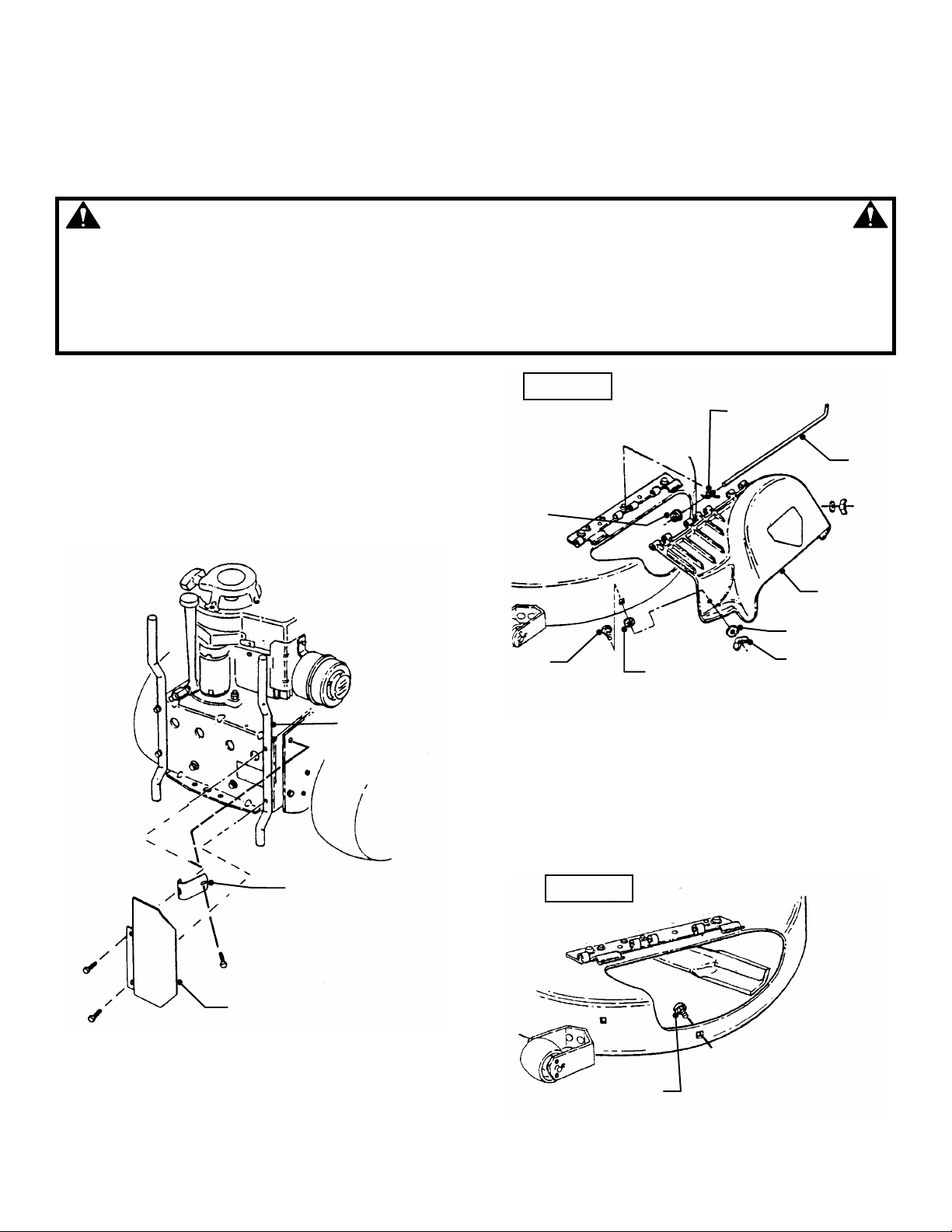
STEP 1: BUMPER REINFORCEMENT BRACKET &
MUFFLER GUARD INSTALLATION (USED ON REAR
ENGINE RIDERS ONLY)
Remove the two screws securing the right side rear
bumper. Remove screw from right rear panel. Install
bumper reinforcement bracket and secure to right rear
panel, secure with screw. See Figure 1. Place muffler
shield against bumper reinforcement bracket and right
side rear bumper, install screws. Tighten securely. See
Figure 1.
REAR ENGINE
RIDER SHOWN
33” DECK
SPRING
HINGE
PIN
HINGE
NUT
DEFLECTOR
RIGHT SIDE
REAR BUMPER
BUMPER
REINFORCEMENT
MUFFLER
SHIELD
FIGURE 1
STEP 2: REMOVAL OF DEFLECTOR (Tractors Only)
A. Remove the hinge nut, spring and hinge pin from
deflector. Remove deflector. Remove wing nut, flat
washer, bolt retainer and bolt from deck. Save for future
use when not bagging grass. See Figure 2A.
FLAT WASHER
BOLT
BOLT RETAINER
(DISCARD)
WING NUT
FIGURE 2A
Note: The deflector on rear engine riders need not be
removed (except on some older models). Lift the deflector
up and out of the way before installing adapter.
B. ADAPTER INSTALLATION
Install the previously removed bolt into the hole in the
center of the discharge opening. See Figure 2B.
33” DECK
INSTALL BOLT
FIGURE 2B
INSTRUCTION No. 2-3822 (Rev. 6, 6/11/99)
Page 2

C. ADAPTER INSTALLATION
Hold the adapter in front of the deck. Align the adapter
lugs with the hinge lug retainers, and then push the
adapter to the rear.
HINGE LUG
RETAINERS
ADAPTER
33” DECK
LOOSEN
BOLTS IF
NECESSARY
ADAPTER
LUGS
PUSH ADAPTER TO
THE REAR TO SEAT
LUGS UNDER RETAINERS
Loosen bolts (see Figure 2C) & bump the adapter, if
necessary, to force the lugs under the lug retainers.
Secure the adapter to the deck with a flat washer and
wing nut. Tighten bolts. See Figure 2C.
RETIGHTEN
BOLTS
FLAT WASHER
WING NUT
BOLT
ADAPTER SHOWN
IN OPERATING
POSITION
FIGURE 2C
STEP 3: COVER/FRAME INSTALLATION
Lower cover/frame structure into position on bumper. Secure each side of structure as follows: Insert one 5/16 x 1-11/16”
clevis pin through top hole at each side of cover/frame structure as shown in Figure 3 and secure with 3/32 x 1-1/2” hairpin
cotter.
NOTE: When Rear Engine Rider is equipped with two-piece post style bumper (as shown in Figure 1) install clevis pin in
lower hole at each side of cover/frame structure.
HAIRPIN
COVER/FRAME
ASSEMBLY
CLEVIS
PIN
GRASS
CATCHER
LATCH
BUMPER
FIGURE 3
2
Page 3

STEP 4: GRASS BAG INSTALLATION
Move the latch aside, then slide the grass bag into the frame with open mesh to the rear of the mower. Secure bag with latch.
See Figure 4.
BAG SUPPORT ROD
BAG ROD ON TOP OF
BAG SUPPORT ROD
MOVE LATCH ASIDE
TO INSTALL BAG
OPEN MESH SIDE
TO REAR OF
MOWER AWAY
FROM ENGINE
COVER/FRAME
ASSEMBLY
FIGURE 4
STEP 5: GRASS TUBE INSTALLATION
A. Slide upper end of grass tube into opening of cover/frame structure.
B. Slide lower end of grass tube over adapter end and rotate tube towards mower to secure handle hook under latch. See
Figure 5.
COVER/FRAME
STRUCTURE
FIGURE 5
3
Page 4

SINGLE BAG GRASS CATCHER ILLUSTRATION
4
Page 5

SINGLE BAG GRASS CATCHER ILLUSTRATION
(Continued)
5
Page 6

SINGLE BAG GRASS CATCHER PARTS LIST
ITEM PART NO. DESCRIPTION
1 5-1948 TOP, Container
2 1-6108 SKIRT, Dust
3 2-9840 WASHER, Faceted (5)
4 4-7973 FRAME, Grass Bag
5 2-9841 CLEVIS PIN, 5/16 x 1-11/16 (2)
6 3-1725 LATCH, Grass Catcher
7 9-0532 SCREW, 10-32 x 1-11/16 Hex Cap
8 9-0376 NUT, 10-32 Hex Lock w/Nylon Insert
9 3-7758 ROD, Bag
10 9-1503 PIN, 3/32 x 1-1/2 Hair (2)
11 1-2556 CONNECTOR, 1/2 x 3” Rod
12 1-9251 BAG, Single Zipperless
13 1-9912 ADAPTER, Bag
14 3-1951 LATCH, Tube
15 1-4517 TUBE, Grass
16 9-1576 NUT, 1/4-20 Hex (3)
17 9-1314 WASHER, 1/4 Lock (3)
18 3-7745 HANDLE, Tube
19 3-1952 BASE, Handle
20 9-1530 BOLT, 1/4-20 X 3/4" (3)
21 9-1537 WING-NUT, 5/16-18 Lock
22 9-1303 BOLT, 5/16-18 X 1" Carriage
-- 7-1677 SHIELD, Muffler (Shown on Page 1)
-- 4-2716 BRACKET, Bumper Reinforcement (Shown on Page 1)
INSTRUCTION No. 2-3822 (REV. 6, 6/11/99)
6
 Loading...