

Page 1
OPERATOR’S
Not for
Reproduction
MANUAL
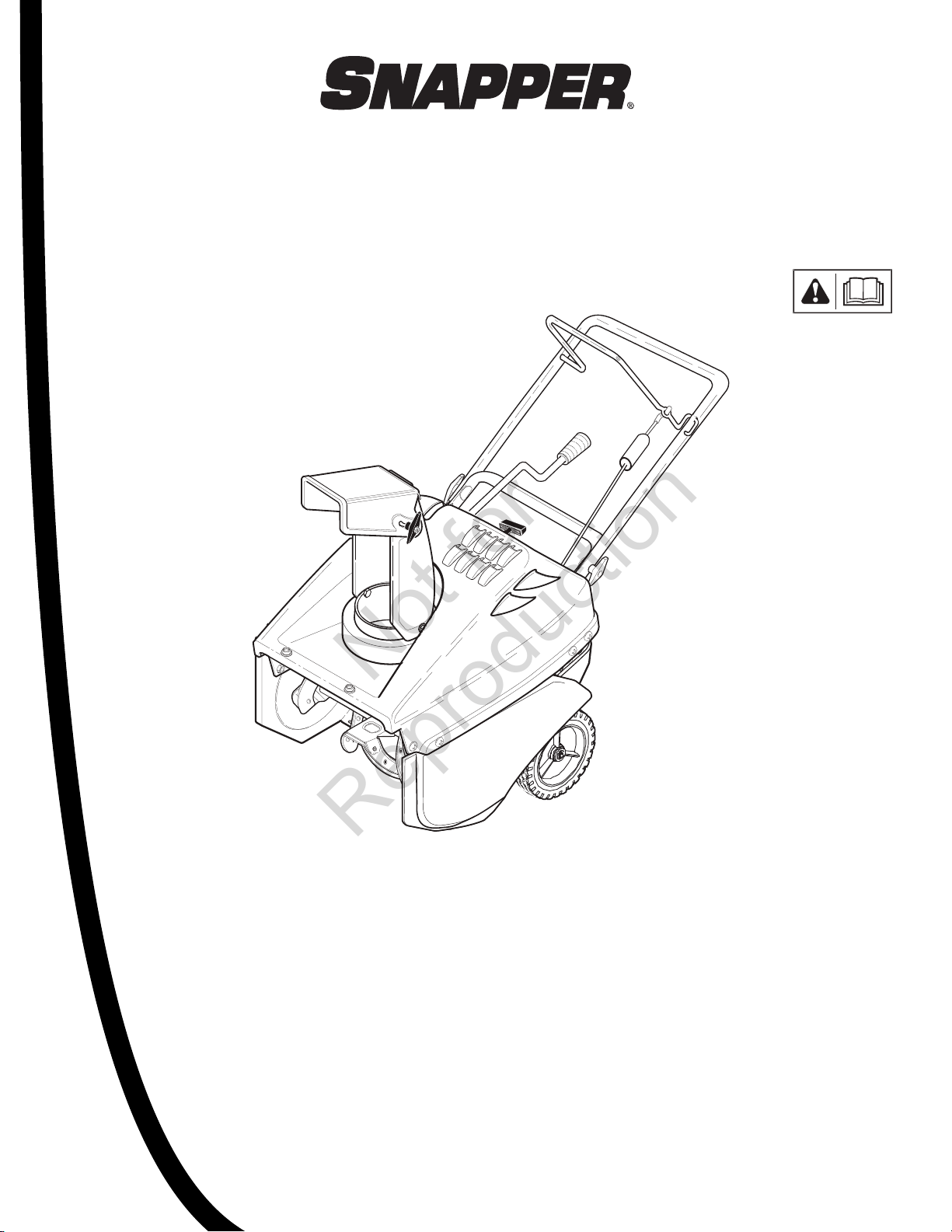
Single Stage
Snowthrower
521E Models
Mfg. No. Description
1695702 521E, Snowthrower
1737682-A
Revision: A
07/2009
Page 2

Thank you for purchasing this quality-built Snapper snow thrower. We’re pleased that you’ve placed your confi dence in the Snapper
Not for
Reproduction
brand. When operated and maintained according to the instructions in this manual, your Snapper product will provide many years of
dependable service.
This manual contains safety information to make you aware of the hazards and risks associated with snow throwers and how
to avoid them. This snow thrower is designed and intended only for snow throwing and is not intended for any other purpose. It is
important that you read and understand these instructions throroughly before attempting to start or operate this equipment. This snow
thrower requires fi nal assembly before use. Refer to the Quck Start Guide for instructions on fi nal assembly procedures. Follow
the instructions completely. Save these instructions for future reference.
Snow Thrower
Revision
Serial Number
Engine
Model Number
Model Number
Date Purchased
The Illustrated Parts List for this machine can be downloaded from www.snapper.com. Please provide model and serial number when
ordering replacement parts.
Snapper
Snapper Products
535 Macon St.
McDonough, GA 30253
1-800-317-7833
Snapper.com
Copyright © 2009 Briggs & Stratton Power Products Group, LLC
Milwaukee, WI, All rights reserved.
Murray is a trademark of Briggs & Stratton Power Products
Group, LLC Milwaukee, WI USA.
Revision
Serial Number
2
Page 3

Table of Contents
Not for
Reproduction
Operator Safety .................................................................... 4
Assembly ............................................................................ 10
Remove Snowthrower from Carton ...................................................... 10
Handle Assembly .................................................................................. 10
Add Oil to the Engine ............................................................................ 11
Add Fuel to the Engine .......................................................................... 11
Before Operate the Snowthrower .......................................................... 12
Operation............................................................................ 13
Snowthrower and Engine Controls ....................................................... 13
Control Snow Discharge ....................................................................... 14
Snow Throwing ..................................................................................... 14
Stop Discharging Snow ........................................................................ 14
Move Forward ....................................................................................... 14
Before Starting the Engine .................................................................... 15
Stop the Engine .................................................................................... 15
Start the Engine .................................................................................... 15
Starting a Cold Engine .......................................................................... 15
Starting a Warm Engine ........................................................................ 16
Frozen Starter ....................................................................................... 16
Clear a Clogged Discharge Chute .......................................................... 16
Snow Throwing Tips ............................................................................. 16
Maintenance ....................................................................... 18
Customer Responsibilities .................................................................... 18
Emissions Control ................................................................................. 18
Engine Power Rating Information ......................................................... 18
After Each Use ...................................................................................... 19
Remove the Top Cover ......................................................................... 19
Lubricate Before Storage ...................................................................... 19
Adjust the Auger Control Cable ............................................................. 20
Remove the Belt Cover ......................................................................... 20
Replace the Auger Drive Belt ................................................................ 21
Replace the Auger ................................................................................. 22
Adjust the Brake Pad ............................................................................. 22
Replace the Spark Plug ......................................................................... 23
Prepare the Snowthrower for Storage .................................................. 23
Order Replacement Parts ...................................................................... 24
Trouble Shooting Chart ........................................................... 25
Warranty Statements .............................................................. 26
Specifi cations ...................................................................... 28
3
Page 4
Operator Safety
Not for
Reproduction
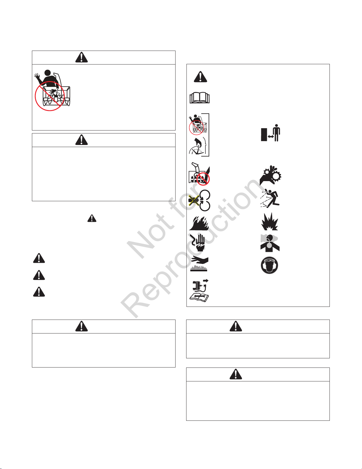
DANGER
AMPUTATION HAZARD
The discharge chute contains a rotating
impeller to throw snow. Never clear or
unclog thedischarge chute with
your hands. Fingers can quickly become
caught and traumatic amputation severe
laceration will result. Always use a
clean-out tool to clear or unclog the
discharge chute.
DANGER
Hand contact with the rotating impeller inside the •
discharge chute is the most common cause of injury
associated with snowthrowers.
This snowthrower is capable of amputating hands and •
feet, and throwing objects. Read and observe all the
safety instructions in this manual. Failure to do so will
result in death or serious injury.
Safety Alert Symbol and Signal Words
The safety alert symbol and signal word (DANGER,
WARNING, CAUTION, or NOTICE) is used to indicate the
likeli- hood and potential severity of personal injury and/or
damage to the product. In addition, a hazard symbol may be
used to represent the type of hazard.
DANGER indicates a hazard which, if not avoided, will
result in death or serious injury.
WARNING indicates a hazard which, if not avoided,
could result in death or serious injury.
CAUTION indicates a hazard which, if not avoided,
could result in minor or moderate injury.
Notice indicates a situation that could result in
damage to the product.
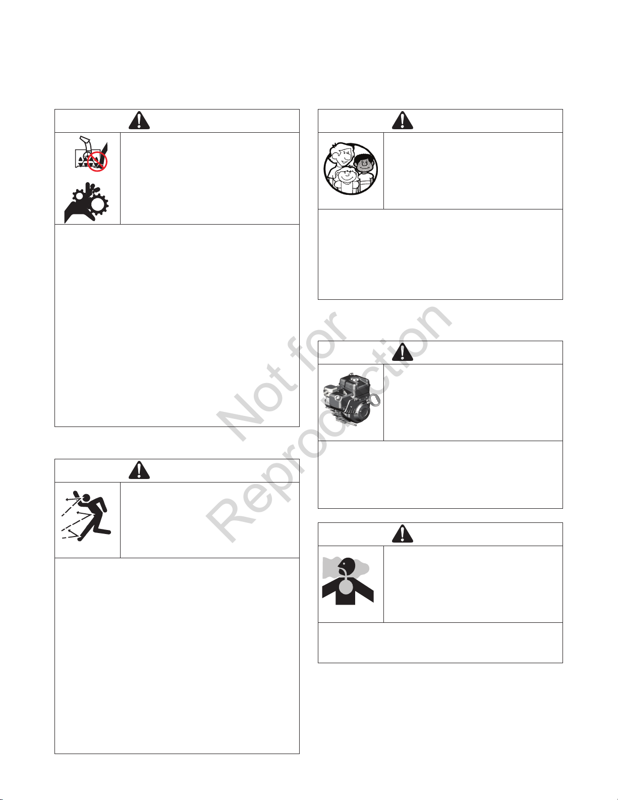
Hazard Symbols and Their Meanings
Safety Alert – Identifies safety information
about hazards that can result in personal injury.
Operator’s Manual – Read and understand
before performing any activity or running
equipment.
Keep a Safe
Rotating Impeller
Rotating Auger
Never Reach into
Rotating Parts
Fire
Shock
Hot Surface
Shut off engine and remove spark plug
connector before performing maintenance or
repair work.
Ditance from
Snowthrower
Rotating Gears
Thrown
Objects
Explosion
Toxic Fumes
Recommended
Ear Protection
for Extended Use
WARNING
U.S.A. Models: Certain components in this product and
its related accessories contain chemicals known to the
state of California to cause cancer, birth defects, or other
reproductive harm. Wash hands after handling.
Certifi cation: This equipment meets the requirements of
ANSI B71.3-2005 for snowthrowers.
U.S.A. Models: The engine exhaust from this product
contains chemicals known to the State of California to
cause cancer, birth defects, or other reproductive harm.
U.S.A. Models: Battery posts, terminals, and related
accessories contain lead and lead components chemicals knownto the State of California to cause
cancer and reproductive harm. Wash hands after
handling.
4
WARNING
WARNING
Page 5
Operator Safety
Not for
Reproduction
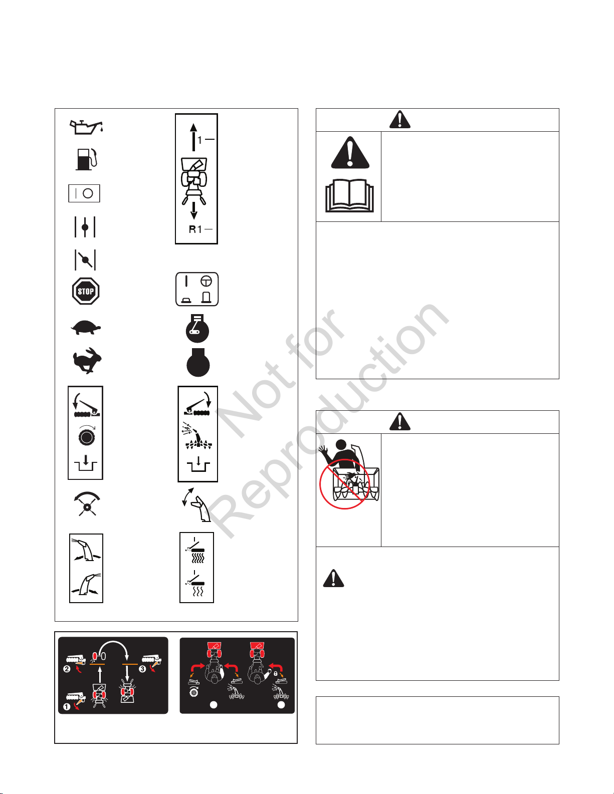
Operating Symbols and Their Meanings
Oil
Fuel
On Off
Choke Off
Choke On
Stop
Slow
Fast
STOP
Foward
Nuetral
Reverse
Electric Start Engage (Down)
& Disengage Up
Engine - Run
Engine - Stop
Read the Manual
DANGER
Read, understand, and follow all the
instructions on the snowthrower and in
the operator’s manual before operating
this unit.
Failure to observe the safet y instructions
in this manual will result in death or
serious injury.
Be thoroughly familiar with the controls and the proper use of the snow •
thrower.
Make sure you are properly trained before operating the snowthrower.•
Know how to stop the unit and disengage the controls quickly.•
Never allow anyone to operate the snowthrower without proper •
instruction.
Always follow the instructions in the operator’s manual, if the •
snowthrower will be stored for an extende d period.
Maintain or replace safety and instruction labels as necessary.•
Never attempt to make major repairs on the snowthrower unless you •
have been properly trained. Improper servicing of the snowthrower can
result in hazardous operation, equipment damage, and voiding of the
product warranty.
Traction Control
Engage (Down)
Auger Clutch
Discharge Chute
(Left and Right)
Auger Control
Engage (Down)
Chute Deflector
(Up and Down)
Heated Hand
Grips
(High and Low)
Discharge Chute
DANGER
Discharge chute contains rotating
impeller to throw snow. Never clear or
unclog the discharge chute with your
hands. Fingers can quickly become
caught in the impeller. Always use a
clean-out tool.
Failure to observe these safety
instructions will result in traumatic
amputation or severe laceration.
TO SAFELY CLEAR A CLOGGED DISCHARGE CHUTE
DANGER: Hand contact with the rotating impeller inside the
discharge chute is the most common cause of injury
associated with snow throwers. Never use your hands to clean
out the discharge chute.
FOLLOW THESE INSTRUCTIONS:
1. Shut OFF the engine.
2. Wait 10 seconds to be sure the impeller blades have
stopped rotating.
3. Always use a clean-out tool, not your hands.
Easy-Turn
Traction Control
TM
1
Free-Hand
Control
2
TM
NOTE: Not all control symbols shown on this page will
appear on your snowthrower. See FEATURES AND
CONTROLS section for the applicable symbols.
5
Page 6
Operator Safety
Not for
Reproduction
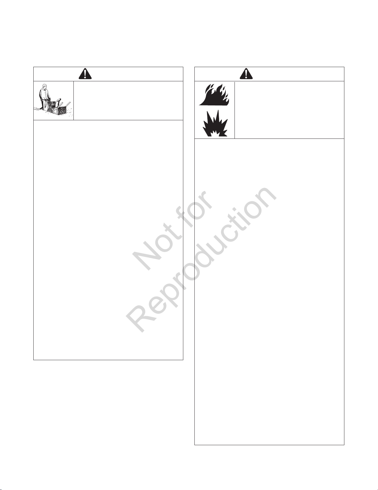
Operation and Equipment Safety
DANGER
This snowthrower is only as safe as the
operator. If it is misused, or not properly
maintained, it can be dangerous.
Remember you are responsible for your
safety and that of those around you.
Keep the area of operation clear of all persons, particularly small •
children and pets.
Thoroughly inspect the area where the snowthrower will be used and •
remove all doormats, sleds, boards, wires, and other foreign objects.
Do not operate the snowthrower without wearing adequate winter •
clothing.
Wear footwear that will improve footing on slippery surfaces.•
Use caution to avoid slipping or falling especially when operating the •
snowthrower in reverse.
Never operate the snowthrower without good visibility or light. Always •
be sure of your footing, and keep a fi rm hold on the handles.
Do not clear snow across the face of slopes. Use extreme caution when •
changing direction on slopes. Do not attempt to clear steep slopes.
Do not overload the machine capacity by attempting to clear snow too •
quickly.
Never operate the snowthrower at high transport speeds on slippery •
surfaces. Look behind the snowthrower and use care when operating in
reverse.
Do not use the snowthrower on surfaces above ground level such as •
roofs of residences, garages, porches, or other such structures or
buildings.
Operators should evaluate their ability to operate the snowthrower safely •
enough to protect themselves and others from injury.
The snowthrower is intended to remove snow only. Do not use the snow •
thrower for any other purpose.
Do not carry passengers.•
After striking a foreign object, shut OFF the engine, disconnect the cord •
on electric motors, thoroughly inspect the snowthrower for any damage,
and repair the damage before restarting and operating the snowthrower.
If the snowthrower vibrates abnormally, shut OFF the engine. Vibration •
is generally a warning of trouble. See an authorized dealer if necessary
for repairs.
For models equipped with electric starting motors, disconnect the power •
cord after the engine starts.
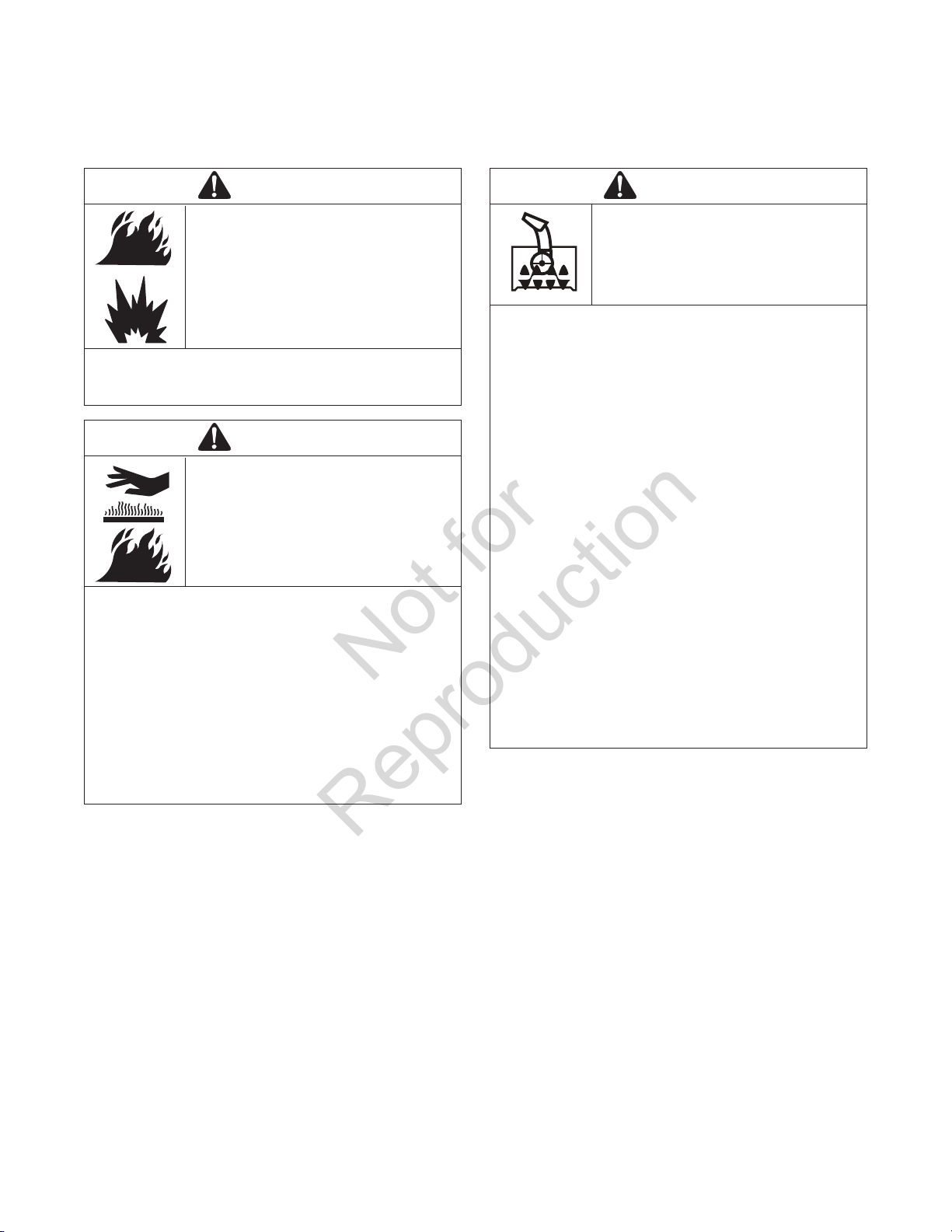
Fuel Handling
DANGER
Fuel and its vapors are extremely
fl ammable and explosive. Always handle
fuel with extreme care.
Failure to observe these safety
instructions can cause a fi re or
explosion which will result in severe
burns or death.
WHEN ADDING FUEL
Turn off engine and let cool at least 2 minutes before removing the fuel •
cap and adding fuel.
Fill fuel tank outdoors or in a well ventilated area.•
Do not overfi ll the fuel tank. To allow for the expansion of gasoline, do •
not fi ll above the bottom of the fuel tank neck.
Keep fuel away from sparks, open fl ames, pilot lights, heat, and other •
ignition sources.
Check fuel lines, cap, and fi ttings frequently for cracks or leaks. Replace •
if necessary.
Use an approved fuel container.•
If fuel spills, wait until it evaporates before starting engine.•
WHEN STARTING ENGINE
Ensure that spark plug, muffl er, fuel cap, and air cleaner (if equipped) •
are in place and secured.
Do not crank the engine with the spark plug removed.•
If fuel is spilled, do not attempt to start the engine, but move the snow •
thrower away from the area of the spill, and avoid creating any source of
ignition, until the fuel vapors have dissipated.
Do not over-prime the engine. Follow the engine starting instructions in •
this manual.
If the engine fl oods, set choke (if equipped) to OPEN/RUN position, •
move throttle (if equipped) to FAST position and crank until engine
starts.
WHEN OPERATING EQUIPMENT
Do not tip the snowthrower at an angle which causes the fuel to spill.•
Do not choke the carburetor to stop the engine. •
Never run the engine with the air cleaner assembly (if equipped) or the •
air fi lter (if equipped) removed.
WHEN CHANGING OIL
If you drain the oil from the top oil fi ll tube, the fuel tank must be empty •
or fuel can leak out and result in a fi re or explosion.
WHEN TRANSPORTING EQUIPMENT
Transport with fuel tank EMPTY, or with fuel shut-off valve OFF.•
WHEN STORING GASOLINE OR EQUIPMENT WITH FUEL
IN TANK
Store away from furnaces, stoves, water heaters, or other appliances •
that have pilot light or other ignition source because they can ignite fuel
vapors.
For models equipped with electric starting motors, disconnect the power •
cord after the engine starts.
6
Page 7
Operator SafetyOperator Safety
Not for
Reproduction
Moving Parts
DANGER
Keep hands, feet, and clothing away
from rotating parts.Rotating parts can
contact or entangle hands, feet, hair,
clothing, or accessories.
Failure to observe these safety
instructions will result in traumatic
amputation or severe laceration.
Whenever cleaning, repairing, or inspecting the snowthrower, make sure •
the engine is OFF, spark plug wire is disconnected, and all moving parts
have stopped.
Do not put hands or feet near or under rotating parts. Keep clear of the •
discharge opening at all times.
Never operate the snowthrower without proper guards, and other safety •
devices in place and working.
Never leave the snowthrower unattended while engine is running. •
Always disengage the auger and traction controls, stop engine, and
remove keys.
Keep all loose clothing away from the front of the snowthrower and •
auger. Scarves, mittens, dangling drawstrings, loose clothes, and pants
can quickly become caught in the rotating device and amputation will
occur. Tie up long hair and remove jewelry.
Run the machine a few minutes after discharging snow to prevent •
freeze-up of the collector/impeller.
Disengage power to the collector/impeller when snowthrower is •
transported or not in use.
Thrown Objects
DANGER
Objects can be picked up by auger and
thrown from chute. Never discharge
snow toward bystanders or allow anyone
in front of the snowthrower. Failure to
observe these safetyinstructions will
result in death or serious injury.
Always wear safety glasses or eye shields while during operation, and •
while performing an adjustment or repair.
Always be aware of the direction the snow is being thrown. Nearby •
pedestrians, pets, or property may be harmed by objects being thrown.
Be aware of your environment while operating the snowthrower. •
Running over items such as, gravel, doormats, newspapers, toys, and
rocks hidden under snow, can all be thrown from the chute or jam in the
auger.
Use extreme caution when operating on or crossing gravel drives, •
walks, or roads.
Adjust the collector housing height to clear gravel or crushed rock •
surface.
Never operate the snowthrower near glass enclosures, automobiles, •
window wells, drop-offs, and the like without proper adjustment of the
dischargechute angle.
Familiarize yourself with the area in which you plan to operate the snow •
thrower. Mark off boundaries of walkways and driveways.
Children
DANGER
Tragic accidents can occur if the operator
is not alert to the presence of children.
Children are often attracted to the unit
and the operating activity. Never assume
that children will remain where you last
saw them.
Keep children out of the area during operation. Children are often •
attracted to the equipment. Be mindful of all persons present.
Be alert and turn unit off if children enter the area.•
Never allow children to operate the unit.•
Use extra care when approaching blind corners, shrubs, trees, or other •
objects that may obscure vision. Children may be present.
Engine Safety
DANGER
Safe operation of the snowthrower
requires the proper care and
maintenance of the engine. Failure to
observe the safety instructions in this
manual will result in death or serious
injury.
Disengage all clutches and shift into neutral before starting the engine.•
Let the engine adjust to outdoor temperatures before starting to clear •
snow.
Use a grounded three-wire plug-in for all snowthrowers equipped with •
electric drive motors or electric starting motors.
DANGER
Safe operation of the snowthrower
requires the proper care and
maintenance of the engine. Failure to
observe the safety instructions in this
manual will result in death or serious
injury.
Start and run engine outdoors. •
Do not run the engine in an enclosed area, even if doors or windows are •
open.
7
Page 8
Operator Safety
Not for
Reproduction
Engine Safety (Continued)
WARNING
Starting engine creates sparking.
Sparking can ignite nearby fl ammable
gases.
Explosion and fi re could result.
If there is natural or LP gas leakage in area, do not start engine.•
Do not use pressurized starting fl uids because vapors are fl ammable.•
WARNING
Running the engine produces heat.
Engine parts, especially muffl er, become
extremely hot.
Failure to observe these safety
instructions could result in severe
thermal burns on contact.
Never touch a hot engine or muffl er. Allow muffl er, engine cylinder, and •
fi ns to cool before touching.
Remove debris from muffl er area and cylinder area.•
Install and maintain in working order a spark arrester before using •
equipment on forest-covered, grass-covered, or brush-covered
unimproved land.
• U.S.A. Models: It is a violation of California Public Resource Code
Section 4442 to use or operate the engine on or near any forestcovered, brush-covered, or grass-covered land unless the exhaust
system is equipped with a spark arrester meeting any applicable local or
state laws. Other states or federal areas may have similar laws.
Maintenance and Storage
WARNING
This snowthrower must be properly
maintained to ensure safe operation
and performance. Failure to observe the
safety instructions in this manual could
result in death or serious injury.
When performing any maintenance or repairs on the snowthrower, shut •
OFF the engine, disconnect spark plug wire, and keep the wire away
from the plug to prevent someone from accidently starting the engine.
Check shear bolts and other hardware at frequent intervals for proper •
tightness to be sure the snowthrower is in safe working condition.
Keep nuts and bolts tight and keep snowthrower in good condition.•
Never tamper with safety devices. Check their proper operation regularly •
and make necessary repairs if they are not functioning properly.
Components are subject to wear, damage, and deterioration. Frequently •
check components and replace with recommended parts, when
necessary.
Check control operation frequently. Adjust and service as required.•
Use only factory authorized replacement parts when making repairs.•
Always comply with factory specifi cations on all settings and •
adjustments.
Only authorized service locations should be utilized for major service •
and repair requirements.
Use only attachments and accessories approved by the factory (such as •
wheel weights, counterweights, or cabs).
Never attempt to make any adjustments while the engine is running •
(except when specifi cally recommended by the factory).
Do not allow grease or oil to contact the rubber friction wheel or the disc •
drive plate. If the disc drive plate or friction wheel come in contact with
grease or oil, damage to the rubber friction wheel will result.
8
Page 9
Safety Decals
Not for
Reproduction
This unit has been designed and manufactured to provide
you with the safety and reliability you would expect from an
industry leader in outdoor power equipment.
Although reading this manual and safety instructions it
contains will provide you with the necessary basic knowledge
to operate this equipment safely and effectively, we have
placed several safety labels on the unit to remind you of this
important information while you are operating your unit.
All WARNING, CAUTION, and instructional messages on your unit
should be carefully read and obeyed. Personal bodily injury can
result when these instructions are not followed. The information is
for your safety and it is important.
8
5
The safety decals below are on your unit. If any of these
decals are lost or damaged, replace them at once. See your
local dealer for replacements. These labels are easily applied
and will act as a constant visual reminder to you, and others
who may use the equipment, to follow the safety instructions
necessary for safe, effective, operation.
Note: Not all control symbols shown on this page will appear
on your snowthrower. See FEATURES AND CONTROLS
section for the applicable symbols.
7
3
4
9
6
REF NO. PART NO. DESCRIPTION
1 - - - - - - *Decal, EPA, Mass
2 728046 Decal, Electric Start (EN/FR)
3 1742294 Decal, Dash Panel (EN/FR)
4 276063 Decal, Briggs & Stratton Logo
5 1737831 Decal, 521E
6 723023 Decal, Warning Hot Muffl er
7 723710 Decal, Auger Control
8 728042 Decal, Danger Chute
9 728043 Decal, Danger Auger, Foot
VIEW FROM REAR
2
1
9
Page 10
ASSEMBLY
Not for
Reproduction
Read and follow the assembly and adjustment
instructions for your snowthrower. All fasteners are in the parts bag. Do not discard any
parts or material until the unit is assembled.
WARNING: Before doing any assembly
or maintenance to the snowthrower,
remove the wire from the spark plug.
NOTE: In this instruction book, left and right
describe the location of a part from the operator’s
position behind the unit.
NOTE: Torque is measured in foot pounds (metric
Nm). This measurement describes how tight a nut
or bolt must be. The torque is measured with a
torque wrench.
PARTS BAG CONTENTS
1 - Electric Start Cord (Not Shown)
1 - Owner’s Manual
1 - Fuel Stabilizer
1 - Container Oil 5W30
4. Cut down all four corners of the carton and lay the
side panels flat.
5. Cut off the plastic bag that covers the snowthrower.
6. Hold onto the lower handle and pull the snowthrower
off the carton.
CAUTION: DO NOT back over cables.
7. Remove the packing material from the handle as sembly.
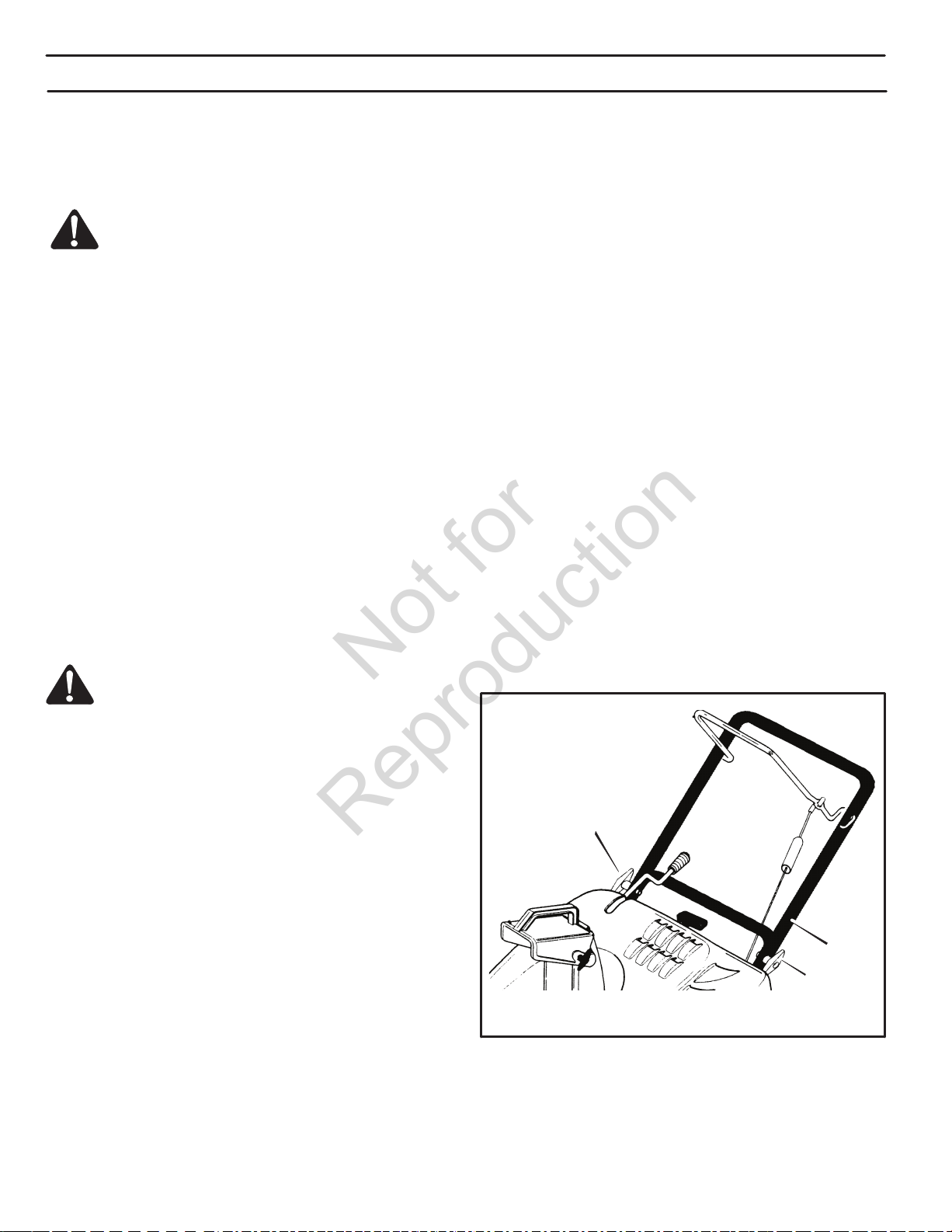
HOW TO ASSEMBLE THE HANDLE
1. Remove the packing material from the upper and
lower handles.
2. (Figure 1) Loosen the knobs (1) on each side of
the handle (2).
3. Raise the upper handle (2) to the operating posi tion. Hold the upper handle (2) apart to prevent
scratching the lower handle.
TOOLS REQUIRED FOR ASSEMBLY
1 − Knife
WARNING: Always wear safety glasses
or eye shields while assembling the
snowthrower.
Figure 3 shows the snowthrower in the operating
position.
References to the right or left hand side of the snow
thrower are from the viewpoint of the operator’s
position behind the unit.
HOW TO REMOVE THE SNOWTHROWER
FROM THE CARTON
1. Locate and remove the container of oil.
2. Locate all parts that are packed separately and
remove from the carton.
NOTE: Make sure the cables are not caught
between the upper and lower handle.
4. Tighten the knobs.
1
2
1
Figure 1
3. Remove and discard the packing material from
around the snowthrower.
10
Page 11

ASSEMBLY
Not for
Reproduction
ADD OIL TO THE ENGINE
NOTE: Engine may already contain some
residual oil. Check frequently when filling the
crankcase. DO NOT overfill.
The snow thrower was shipped with a container
of 5W30 motor oil. This oil must be added to the
engine before operating.
OIl Fill Cap/Dipstick
Figure 2
1. Make sure the unit is level.
ADD FUEL TO THE ENGINE
This engine is certied to operate on gasoline or
petrol. The emissions control system for this engine is
EM (Engine Modications).
WARNING: Alcohol blended fuels (called
gasohol or those using ethanol or methanol)
can attract moisture which leads to separation and
formation of acids during storage. Acidic gas can
damage the fuel system of an engine while in storage.
NOTE: To avoid engine problems, the fuel system must
be emptied before storage for 30 days or longer. Start the
engine and let it run until the fuel lines and carburetor are
empty. Use fresh fuel next season. See the Storage section
in this manual for additional information.
Fill the fuel tank only with fresh, clean, unleaded regular,
unleaded premium, or reformulated automotive fuel with
a minimum of 85 octane. DO NOT use leaded gasoline
or petrol. Make sure that the container you pour the fuel
is free from rust or foreign particles. Never use fuel that
may be stale from long periods of storage in the container.
2. Remove the oil fill cap/dipstick and fill
the crankcase to “FULL” line on dipstick.
DO NOT overfill.
3. Pour the oil slowly into the engine oil fill.
DO NOT overfill. After adding oil, wait one
minute and then recheck the oil level.
4. Tighten the oil fill cap/dipstick securely each
time you check the oil level.
NOTE: Synthetic oil can assist with starting in
extreme cold temperatures. Synthetic 5W30 is
acceptable for all temperatures. Do NOT mix oil
with unleaded gasoline.
1. Stop the engine. Before you remove fuel
cap, let the engine cool at least 2 minutes.
2. Remove the fuel cap. Fill the fuel tank to
approximately 1-1/2 inches (38 mm) below
top of neck to allow for fuel expansion. Be
careful not to overfill.
3. Replace the fuel cap before starting the engine.
WARNING: Gasoline and petrol and its vapors
are extremely flammable and explosive. Fire or
explosion can cause severe burns or death.
• Turn engine off and let engine cool at least 2 minutes
removing the gas cap.
• Fill fuel tank outdoors or in well-ventilated area.
• Keep gasoline away from sparks, open flames, pilot
lights, head, and other ignition sources.
• If fuel spills, wait until it evaporates before starting
engine.
11
Page 12

ASSEMBLY
Not for
Reproduction
BEFORE YOU OPERATE
Before you operate your new snow thrower,
please review the following checklist:
• Make sure all assembly instructions have been
completed.
• Make sure the discharge chute rotates freely.
• Make sure that no loose parts remain in the
carton.
As you learn how to properly use the snow
thrower, pay extra attention to the following
important items:
• Make sure the engine oil is at the proper
level. For the type engine oil to use, see the
Engine Manufacturer’s manual.
• Make sure the fuel tank is filled with clean,
fresh, unleaded gasoline or petrol with a
minimum of 85 octane.
.
• Become familar with the location of all
controls and understand their function.
• Before starting the engine, make sure all
controls operate correctly.
KNOW YOUR SNOWTHROWER
Read this Instruction Book and safety rules before
operating the snow thrower. Compare the illustration
with your snow thrower to familiarize yourself with
the location of various controls and adjustments.
12
Page 13

OPERATION
Not for
Reproduction
4
2
3
5
1
7
11
12
8
10
6
9
Figure 3
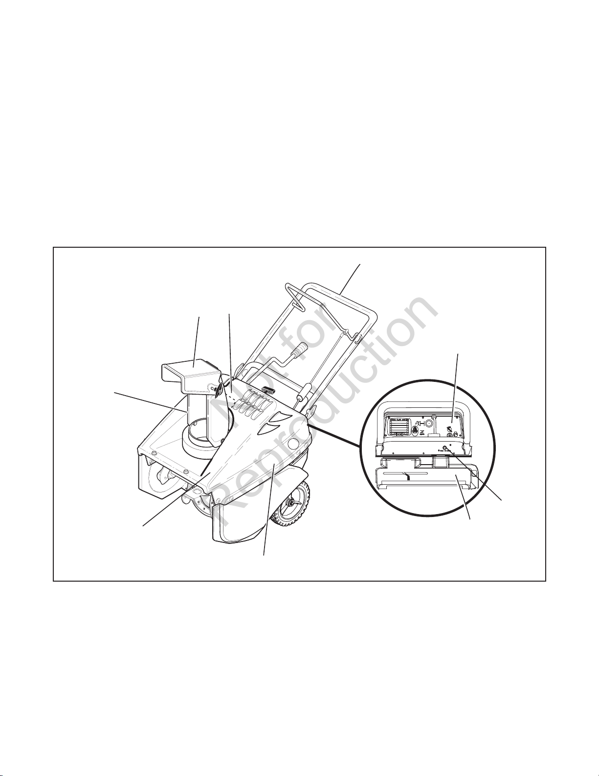
Control and Equipment Features (Figure 3)
Crank Assembly (1) - Changes the direction of
the discharge chute.
Chute Deflector (2) - Changes the distance the
snow is thrown.
Discharge Chute (3) - Changes the direction the
snow is thrown.
Auger Drive Lever (4) - Starts and stops the auger
which propels the snow thrower.
Auger Blades (5) - Cuts through the snow.
Engine Features (Figure 3)
Stop Switch (6) - If equipped, move to the ON position
to start the engine.
Ignition Key (6) - If equipped, insert and turn to the
ON position to start the engine.
Primer Button (7) - Injects fuel directly into the
carburetor for fast starts in cold weather.
Engine Start Button (8) - On electric start models,
used to start the engine.
Switch Box (9) - On electric start models, used to
attach electrical power cord.
Recoil Starter Handle (10) - Used to manually
start the engine.
Choke Control (11) - Used to start a cold engine.
Spark Plug Access Panel (12) - Remove to access
the spark plug.
13
Page 14

OPERATION
Not for
Reproduction
HOW TO CONTROL DISCHARGE
OF SNOW
WARNING: Never direct the discharge of snow toward bystanders.
WARNING: Always stop the engine
before unclogging the discharge chute
or the auger housing and before leaving the
snow thrower.
1. (Figure 3) Turn the crank assembly (1) to
change the discharge direction of the snow.
2. (Figure 4) Loosen the wing knob (1) on the
chute deflector (2).
2
2
WARNING: The operation of any snow
thrower can result in foreign objects
being thrown into the eyes, which can result
in severe eye damage. Always wear safety
glasses or eye shields while operating the
snow thrower. We recommend standard
safety glasses or use a wide vision safety
mask over your glasses.
HOW TO STOP DISCHARGING SNOW
1. (Figure 3) To stop discharging snow, release
the auger drive lever (4).
2. To stop the engine, turn the ignition key (5)
to the OFF position.
HOW TO MOVE FORWARD
1. (Figure 3) Hold the auger drive lever (4)
against the handle (10). The auger will begin
rotating.
1
3. Move the chute deector (2) up for more distance or
down for less distance.
4. Tighten the wing knob (1).
HOW TO THROW SNOW
1. (Figure 3) Engage the auger drive lever (4).
2. To stop throwing snow, release the
auger drive lever.
1
Figure 4
2. To go forward, raise the handle (10) to allow
the rubber auger blades (5) to contact the
ground. Maintain a firm hold on the handle
(10) as the snow thrower starts to move for ward. Guide the snowthrower by moving the
handle (10) either left or right. Do not attempt
to push the snowthrower.
3. To stop, release the auger drive lever (4).
NOTE: If the auger continues to rotate, see
“How To Adjust The Auger Control Cable” in
the Maintenance section.
14
Page 15

OPERATION
Not for
Reproduction
BEFORE STARTING THE ENGINE
1. Before you service or start the engine,
familiarize yourself with the snow thrower. Be
sure you understand the function and location
of all controls.
2. Make sure that all fasteners are tight.
3. Make sure the fuel tank is filled with fresh,
clean fuel.
4. Before starting the engine, make sure all
controls operate correctly.
HOW TO STOP THE ENGINE
To stop the engine, turn the ignition key to
the OFF position. Keep the ignition key in a
safe place. The engine will not start without
the ignition key.
HOW TO START A COLD ENGINE
1. Fill the fuel tank with fresh, clean fuel. See “Add
Fuel To The Engine” in the Assembly section.
2. Move the choke control to FULL position.
3. (Figure 3) Make sure the auger drive lever (4) is
in the disengaged (released) position.
4. Insert the ignition key (6) and turn to the ON
position.
5. Move the choke control (11) to the full choke
position.
6. (Electric Start) Connect the power cord to the
switch box (9) located on the engine.
7. (Electric Start) Plug the other end of the power
cord into a three-hole, grounded AC receptacle.
(See the WARNING in this section.)
HOW TO START THE ENGINE
NOTE: An electric starter kit can be added
to recoil start engines. Electric starter kits are
available from your nearest authorized service
center.
WARNING: The starter is equipped with
a three-wire power cord and plug and is
designed to operate on AC household current.
Carefully follow all instructions in the “How To
Start The Engine” section. Make sure that your
house wiring is a three-wire grounded system.
To connect an AC power cord, always connect
the power cord to the switch box on the engine
first. Then, plug the other end into the three-hole
grounded receptacle. When disconnecting the
power cord, always unplug the end from the
three-hole grounded receptacle first.
8. Push the primer button (7) two times. Every time
you push the primer button (7), wait two seconds.
9. (Electric Start) Push on the electric start button
(8) until the engine starts. Do not crank for more
than 10 seconds at a time.The electric starter is
thermally protected. If the electric starter over heats, it will automatically stop and can be re started when it has cooled to a safe temperature.
A wait of about 5 to 10 minutes is required to
allow the electric starter to cool.
10. (Recoil Start) Rapidly pull the recoil starter
handle (10). Do not allow the recoil starter han dle (10) to snap back. Slowly return the recoil
starter handle (10).
11. If the engine does not start in 5 or 6 tries, see the
“Troubleshooting Chart” instructions.
12. (Electric Start) When the engine starts, release
the electric start button (8) and move the choke
control (14) to 1/2 choke position. When the en gine runs smoothly, move the choke control (11)
to the OFF position.
15
Page 16

OPERATION
Not for
Reproduction
13. (Electric Start) First disconnect the power
cord from the three-hole receptacle. Then,
disconnect the power cord from the switch
box (11).
NOTE: In temperatures below 0° F (-18° C), allow
the engine to warm up for several minutes before
blowing snow.
WARNING: Never run the engine indoors
or in enclosed, poorly ventilated areas.
Engine exhaust contains carbon monoxide, an
odorless and colorless deadly gas. Keep hands,
feet, hair, and loose clothing away from any moving parts located on the engine or the snow thrower. The temperature of muffler and nearby areas
may exceed 150° F (65° C). Avoid these areas.
HOW TO START A WARM ENGINE
(Figure 3) If an engine has been running and is
still warm, leave the choke control (11) in the OFF
position and do not push the primer button (7). If
the engine fails to start, follow the instructions “How
To Start A Cold Engine.”
NOTE: Do not use the primer button (7) to start
a warm engine.
HOW TO START A WARM ENGINE WITH A
FROZEN STARTER
If the electric starter is frozen and will not turn
the engine, follow the instructions below.
1. With the engine running, quickly pull the re coil starter handle (10) three or four times with
a continuous full arm stroke. This will produce a
loud clattering sound that is not harmful to the
engine or starter.
2. Stop the engine. Wipe all snow and moisture
from the carburetor cover, control levers, and
cables. Also move the choke control (11) and
recoil starter handle (10) several times.
HOW CLEAR A CLOGGED DISCHARGE CHUTE
WARNING: Hand contact with the rotating
impeller inside the discharge chute is the
most common cause of injury associated with
snow blowing. Never use your hand to clean out
the discharge chute.
To Clear The Chute:
• Shut off the engine
• Wait 10 seconds to be sure that the impeller blades
have stop rotating.
• Always use a clean-out tool, not your hands.
How To Use A Clean-Out Tool:
• Release the auger drive lever.
• Pull out or remove the safety/ignition key.
• Disconnect the spark plug wire.
• Do not place your hands in the auger or dis-
charge chute. Use a clean-out tool to remove
snow or debris.
SNOW THROWING TIPS
1. (Figure 3) Pull out the recoil starter handle (10)
as far as possible.
2. Quickly release the recoil starter handle (10)
to snap back against the recoil starter.
If the engine still fails to start, repeat the two previous steps until the engine starts. Then, continue
with the directions “How To Start A Cold Engine.”
To help prevent the possible freeze-up of the
recoil starter and of the engine controls, proceed
as follows after each snow removal job.
1. This snow thrower will propel itself forward when
the handle is raised enough to cause the auger
blades to contact the ground. The auger should
stop when auger control bar is released. If it does
not stop, see “How To Adjust The Auger Control
Cable” in the Maintenance section.
2. Most efficient snow throwing is accomplished when
the snow if removed immediately after it falls.
16
Page 17

OPERATION
Not for
Reproduction
3. For complete snow removal, slightly overlap
leach previous path.
4. When possible, discharge the snow down wind.
5. The distance the snow will be discharged can
be adjusted by moving the discharge chute
deflector. Raise the deflector for more distance
or lower the deflector for less distance.
6. In windy conditions, lower the chute deflector
to direct the discharged snow close to the
ground where it is less likely to blow into un wanted areas.
7. For safety and to prevent damage to the snow
thrower, keep the area to be cleared free of
stones, toys, and other foreign objects.
8. Do not use the auger propelling feature when
clearing gravel or crushed rock driveways. Move
the handle down to slightly raise the auger.
Dry and Average Snow
1. Snow up to eight inches deep can be removed
rapidly and easily by walking at a moderate
rate. For snow drifts of a greater depth, slow
your pace to allow the discharge chute to dis pose of the snow as rapidly as the auger receives
the snow.
2. Plan to have the snow discharged in the direction
the wind is blowing.
Wet Packed Snow
Move slowly into wet, packed snow. It the wet,
packed now causes the auger to slow down or
the discharge chute begins to clog, back off and
begin a series of short back and forth jabs into
the snow. These short back and forth jabs, four
to six inches, will “belch” the snow from the chute.
9. The forward speed of the snowthrower is depen dent on the depth and weight of the snow. Exper ience will establish the most effective method of
using the snow thrower under different conditions.
10. After each snow throwing job, allow the engine to
run for a few minutes. The snow and accumulated
ice will melt off the engine.
11. Clean the snowthrower after each use.
12. Remove ice, snow, and debris from the entire
snow thrower. Flush with water to remove all
salt or other chemicals. Wipe snow thrower dry.
Snow Banks And Drifts
In snow of great depth than the unit, use the
same “jabbing” technique described above. Turn
the discharge chute away from the snow bank.
More time will be required to remove snow of this
type than level snow.
17
Page 18

CUSTOMER RESPONSIBILITIES
Not for
Reproduction
SERVICE RECORDS
Fill in dates as you
complete regular
service.
MAINTENANCE
Before
Each
Use
First
2
Hours
Every
5
Hours
Every
10
Hours
Every
25
Hours
Each
Season
Before
Storage
SERVICE DATES
Check And Tighten All Screws and Nuts
Check Spark Plug
Check Drive Belt
Check Fuel
Drain Fuel
Lubricate Chute Control Flange
Check Adjustment of Auger Control Cable
Auger Drive Belt
√ √
√
NOTE: Use the following maintenance section
to keep your unit in good operating condition.
All the maintenance for the engine is in the engine
manufacturer’s instructions. Before you start the
engine, read this book.
WARNING: Before you make an inspection, adjustment (except carburetor), or
repair, disconnect the wire from the spark plug.
EMISSIONS CONTROL
Maintenance, replacement, or repair of the emissions
control devices and systems may be performed by
any non-road engine repair establishment or indivHowever, to obtain a “no charge” emissions control
service, the work must be performed by a factory authorized dealer. See the Emissions Warranty.
GENERAL RECOMMENDATIONS
The warranty on this snowthrower does not cover items
that have been subjected to operator abuse or negligence.
To receive full value from the warranty, the operator must
maintain the snow thrower as instructed in this manual.
√ √
√
√
√
√
√
ENGINE POWER RATING INFORMATION
The gross power rating for individual gas engine models
is labeled in accordance with SAE (Society of Automotive
Engineers) code J1940 (Small Engine Power & Torque Rating
Procedure), and rating performance has been obtained and
corrected in accordance with SAE J1995 (Revision 2002-05).
Torque values are derived at 3060 RPM; horsepower values
are derived at 3600 RPM. Actual gross engine power will be
lower and is aected by, among other things, ambient operating conditions and engine-to-engine variability. Given
both the wide array of products on which engines are
placed and the variety of environmental issues applicable
to operating the equipment, the gas engine will not develop
the rated gross power when used in a given piece of power
equipment (actual "on-site" or net power). This dierence
to due to a variety of factors including, but not limited to,
accessories (air cleaner, exhaust, charging, cooling, carburetor, fuel pump, etc.), application limitations, ambient operating conditions (temperature, humidity, altitude), and
engine-to-engine variability. Due to manufacturing and
capacity limitations, Briggs & Stratton may substitute
an engine of higher rated power for this Series engine.
18
Page 19

MAINTENANCE
Not for
Reproduction
AFTER EACH USE
• Check for any loose or damaged parts.
• Tighten any loose fasteners.
• Check and maintain the auger.
• Check controls to make sure they are
functioning properly.
• If any parts are worn or damaged, replace
immediately.
• Check all safety and instruction decals
and labels. Replace any decals or labels
that are missing or cannot be clearly read.
HOW TO REMOVE THE TOP COVER
1. (Figure 5) Remove the discharge chute (1).
2. Remove the fuel cap.
3. Remove the two nuts and bolts (2) from the
front of the top cover (3).
7. Carefully pull the rear of the top cover (4) up and
over the gas tank.
8. To install the top cover (4), reverse the above
steps.
LUBRICATION BEFORE STORAGE
(Figure 5) Lubricate the chute control ange (7). Apply
a clinging type of grease such as Lubriplate.
3
2
6
4. Remove the two bolts (4) from the left and right
of the top cover (3).
5. Remove the eight screws (5) on the left and
right side of the top cover.
6. Remove the three screws (6) from the top
portion of the control panel.
4
1
7
5
Figure 5
19
Page 20

MAINTENANCE
Not for
Reproduction
HOW TO ADJUST THE AUGER CONTROL
CABLE
The auger control is adjusted at the factory. During
normal use, the auger control cable can become
stretched and the auger drive lever will not properly engage or disengage the auger.
1. (Figure 6) Remove the “Z” hook (1) from the
auger drive lever (2).
2
1
7. (Figure 6) Install the “Z” hook (1) to the
auger drive lever (2).
8. To check the adjustment, start the snowthrower.
Make sure the auger does not rotate when the
auger drive is released.
1
2
2
3
4
Figure 6
2. (Figure 7)
cable adjustment bracket (2).
3. Push the bottom of the auger control cable (3)
through the cable adjustment bracket (2) until
the “Z” hook (6) can be removed.
4. Remove the “Z” hook (4) from the cable adjust ment bracket (2). Move the “Z” hook (4) down to
the next adjustment hole.
5. Pull the auger control cable (3) up through the
cable adjustment bracket (2).
6. Put the cable boot (1) over the cable adjustment
bracket (2).
Figure 7
HOW TO REMOVE THE BELT COVER
1. (Figure 8) If equipped, remove the heat shield (1)
from the rear of the belt cover (2).
2. Remove the four bolts and nuts (3) holding
the belt cover (2) to the auger housing.
3. Remove the one screw (4) holding the belt
cover (2) to the bottom cover (5).
4. To remove, hold the bottom portion of the
belt cover (2) and pull down and out.
5. To install the belt cover (2), reverse the above
steps.
20
Page 21

MAINTENANCE
Not for
Reproduction
3. Move the belt guide (4) away from the drive
belt (1).
5
6
3
3
3
3
1
4. To reduce pressure on the drive belt (1), move
2
6
4
the idler pulley (2) away from the drive belt (1).
Remove the drive belt (1) from between the
brake pad (3) and the roller (5).
5. Remove the old drive belt (1).
6. To install the new drive belt (1), reverse the
above steps.
Figure 8
HOW TO REPLACE THE AUGER DRIVE BELT
The drive belt is of special construction and must be
replaced with original factory replacement belt available from your nearest authorized service center.
1. Remove the belt cover. See “How To Remove The
Belt Cover.”
2. (Figure 9) Remove the drive belt (1) from the idler
pulley (2).
2
3
7. Make sure the drive belt (1) is seated properly
on the pulleys.
8. (Figure 10) Set the belt guide (1) to 3/32”
clearance.
NOTE: When the auger control lever is en-
gaged, the belt guide (1) must be 3/32” (2 mm)
from the drive belt (2).
9. Install the belt cover. See “How To Remove
The Belt Cover.”
4
5
1
Figure 9
21
2
3/32”
1
Figure 10
Page 22

MAINTENANCE
Not for
Reproduction
HOW TO REPLACE THE AUGER
1. Remove the belt cover. See “How To Remove
The Belt Cover.”
2. Remove the drive belt. See “How To Replace
The Drive Belt.”
3
6
4
2
5
1
Figure 11
HOW TO ADJUST THE BRAKE PAD
IMPORTANT: An adjustment is only necessary
if the brake pad has become loose or has been
removed. To adjust, proceed as follows:
1. Remove the top cover. See “How To Remove
The Top Cover.”
2. Remove the belt cover. See “How To Remove
The Belt Cover.”
3. Tie the auger drive lever to the handle. This
will engage the drive system.
4. (Figure 12) Loosen the screw and nut that
secure the brake pad arm (1).
5. Set the clearance between the brake pad
(2) and the drive belt (3) to 1/8 inch (3 mm).
6. Tighten the screw and nut that secure the
brake pad arm (1).
7. Connect the wire to the spark plug.
3. (Figure 11) Remove the auger pulley (1) from
the auger shaft (threads are left hand; turn clock wise to remove).
4. To keep the auger (2) from rotating, set a
2” x 4” piece of wood (3) on the center pad dle (4) to secure the auger (2).
5. Remove the fasteners from the bearing as sembly (4). Remove the bearing assembly
(4) from the auger housing (5).
6. Slide the auger (2) out the bearing assem bly on the right side of the snow thrower.
7. Tip the auger (2) enough to allow the auger
(2) to slide out of the auger housing (6).
8. To install auger (2), reverse the above steps.
1
3
2
Figure 12
22
Page 23

MAINTENANCE
Not for
Reproduction
HOW TO REPLACE THE SPARK PLUG
NOTE: This spark plug ignition system meets
all requirements of the Canadian IntereferenceCausing Equipment Regulations (ICES-002).
NOTE: This engine complies with all current
Australian and New Zealand limitations electromagnetic interconference.
The spark plug is housed in the engine compartment under the top cover and cannot be seen
under normal conditions.
1. (Figure 13) Open the spark plug access
door (1) on the control panel.
2. The spark plug and wire are now visible.
3. Remove the spark plug wire.
4. Clean the area around the spark plug base
to prevent dirt from entering the engine when
the spark plug is removed.
5. Remove the spark plug.
6. Check the spark plug. If the spark plug is
cracked, fouled, or dirty, it must be replaced.
7. (Figure 14) Set the gap between the elec trodes of the new spark plug at .030 inch.
Next, install the spark plug in the cylinder
head and firmly tighten. Recommended
torque is 18 to 20 ft-lbs.
Figure 14
HOW TO PREPARE THE SNOWTHROWER
FOR STORAGE
repair, disconnect the wire from the spark plug.
WARNING: Before you make an inspection, adjustment (except carburetor), or
1
Figure 13
1. Drain the fuel tank.
2. Let the engine run until it is out of gasoline or
petrol.
3. Remove the spark plug from the cylinder.
a. Pour one ounce of oil into the cylinder.
b. Slow pull the recoil-start grip so that the oil
will protect the cylinder.
c. Install a new spark plug in the cylinder.
4. Thorougly clean the snow thrower.
5. Lubricate all lubrication points. See the Mainten ance section.
23
Page 24

MAINTENANCE
Not for
Reproduction
6. Be sure that all nuts, bolts, and screws are
securely fastened. Inspect all visible moving
parts for damage, breakage, and wear. Replace
if necessary.
7. Cover the bare metal parts of the blower
housing and auger with spray rust pre ventative lubricant.
8. Put the unit in a building that has good
ventilation.
9. If the machine must be stored outdoors,
block up the snow thrower to be sure the
entire machine is o the ground.
10. Cover the snow thrower with a suitable
protective cover that does not retain
moisture. Do not use plastic.
HOW TO ORDER REPLACEMENT PARTS
Use only manufacturer’s authorized or approved
replacement parts. Do not use attachments
or accessories not specically recommended for
this unit. In order to obtain proper replacement you
must supply the model number (see nameplate).
Warranty service is available only through Authorized
Service Dealers.
24
Page 25

TROUBLESHOOTING CHART
Not for
Reproduction
Trouble Cause Correction
Difficulty starting Defective spark plug. Replace spark plug.
Water or dirt in fuel system. Use carburetor bowl drain to flush and
refill with fresh fuel.
Engine runs erratic Blocked fuel line, empty gas tank,
or stale gasoline/petrol.
Engine stalls Unit running on CHOKE. Set choke lever to RUN position.
Engine runs erratic; loss of
power
Excessive vibration Loose parts; damaged impeller. Stop engine immediately and disconnect
Unit fails to propel itself Drive belt loose or damaged. Replace drive belt.
Unit fails to discharge snow
Water or dirt in fuel system. Use carburetor bowl drain to flush and
Auger drive belt loose or damaged. Adjust auger drive belt; replaced if dam-
Auger control cable not adjusted
correctly.
Discharge chute clogged. Stop engine immediately and disconnect
Foreign object lodged in auger. Stop engine immediately and disconnect
Clean fuel line; check fuel supply; add
fresh fuel.
refill with fresh fuel.
spark plug wire. Tighten all bolts and
make all necessary repairs. If vibration
continues, have the unit serviced by a
competent repairman.
aged.
Adjust auger control cable.
spark plug. Clean discharge chute and
inside of auger housing.
spark plug wire. Remove object from
auger.
25
Page 26

BRIGGS & STRATTON POWER PRODUCTS GROUP, L.L.C. OWNER WARRANTY POLICY
Not for
Reproduction
LIMITED WARRANTY
Briggs & Stratton Power Products Group, LLC will repair and/or replace, free of charge, any part(s) of the equipment that is
defective in material or workmanship or both. Briggs & Stratton Corporation will repair and/or replace, free of charge, any
part(s) of the Briggs and Stratton engine* (if equipped) that is defective in material or workmanship or both. Transportation
charges on product submitted for repair or replacement under this warranty must be borne by purchaser. This warranty is
effective for the time periods and subject to the conditions stated below. For warranty service, find the nearest Authorized
Service Dealer using our dealer locator at www.BriggsandStratton.com or www.SimplicityMfg.com.
There is no other express warranty. Implied warranties, including those of merchantability and fitness for a particular
purpose, are limited to one year from purchase or to the extent permitted by law. Liability for incidental or consequential
damages are excluded to the extent exclusion is permitted by law.
Some states or countries do not allow limitations on how long an implied warranty lasts, and some states or countries do
not allow the exclusion or limitation of incidental or consequential damages, so the above limitation and exclusion may not
apply to you. This warranty gives you specific legal rights and you may also have other rights which vary from state to state
or country to country.
The warranty period begins on the date of purchase by the first retail consumer or commercial end user, and continues for
WARRANTY PERIOD
Item Consumer Use Commercial Use:
Equipment 2 Years 90 Days
Engine* 2 Years 90 Days
Battery 1 Year 1 Year
the period of time stated above. “Consumer use” means personal residential household use by a retail consumer. “Commercial
use” means all other uses, including use for commercial, income producing or rental purposes. Once product has experienced
commercial use, it shall thereafter be considered as commercial use for purposes of this warranty.
No warranty registration is necessary to obtain warranty on Briggs & Stratton products. Save your proof of purchase receipt. If you
do not provide proof of the initial purchase date at the time warranty service is requested, the manufacturing date of the product will
be used to determine warranty eligibility.
We welcome warranty repair and apologize to you for being inconvenienced. Warranty service is available only through servicing
ABOUT YOUR WARRANTY
dealers authorized by Briggs & Stratton or BSPPG, LLC.
Most warranty repairs are handled routinely, but sometimes requests for warranty service may not be appropriate. This warranty
only covers defects in materials or workmanship. It does not cover damage caused by improper use or abuse, improper
maintenance or repair, normal wear and tear, or stale or unapproved fuel.
Improper Use and Abuse - The proper, intended use of this product is described in the Operator’s Manual. Using the product in
a way not described in the Operator’s Manual or using the product after it has been damaged will void your warranty. Warranty is
not allowed if the serial number on the product has been removed or the product has been altered or modified in any way, or if the
product has evidence of abuse such as impact damage, or water/chemical corrosion damage.
Improper Maintenance or Repair - This product must be maintained according to the procedures and schedules provided in the
Operator’s Manual, and serviced or repaired using genuine Briggs & Stratton parts. Damage caused by lack of maintenance or use
of non-original parts is not covered by warranty.
Normal Wear - Like all mechanical devices, your unit is subject to wear even when properly maintained. This warranty does not
cover repairs when normal use has exhausted the life of a part or the equipment. Maintenance and wear items such as filters,
belts, cutting blades, and brake pads (engine brake pads are covered) are not covered by warranty due to wear characteristics
alone, unless the cause is due to defects in material or workmanship.
Stale Fuel - In order to function correctly, this product requires fresh fuel that conforms to the criteria specified in the Operator’s
Manual. Damage caused by stale fuel (carburetor leaks, clogged fuel tubes, sticking valves, etc) is not covered by warranty.
* Applies to Briggs and Stratton engines only. Warranty coverage of non-Briggs and Stratton engines is provided by the engine manufacturer.
26
Page 27

CALIFORNIA, U.S. EPA, AND BRIGGS & STRATTON CORPORATION EMISSIONS CONTROL WARRANTY STATEMENT
Not for
Reproduction
YOUR WARRANTY RIGHTS AND OBLIGATIONS
Effective November 2008
The California Air Resources Board, U.S. EPA, and Briggs & Stratton (B&S)
are pleased to explain the emissions control system warranty on your Model
Year 2008 and later engine/equipment. In California, new small off-road engines
must be designed, built, and equipped to meet the State’s stringent anti-smog
standards. B&S must warrant the emissions control system on your engine/
equipment for the periods of time listed below provided there has been no abuse,
neglect, or improper maintenance of your small off-road engine.
Your emissions control system may include parts such as the carburetor or
fuel injection system, fuel tank, ignition system, and catalytic converter. Also
included may be hoses, belts, connectors, sensors, and other emissions-related
assemblies. Where a warrantable condition exists, B&S will repair your engine/
equipment at no cost to you including diagnosis, parts, and labor.
Manufacturer’s Warranty Coverage:
Small off-road engines are warranted for two years. If any emissions-related part
on your engine/equipment is defective, the part will be repaired or replaced by
B&S.
Owner’s Warranty Responsibilities:
• As the small engine/equipment owner, you are responsible for the performance
of the required maintenance listed in your owner’s manual. B&S recommends that
you retain all receipts covering maintenance on your engine/equipment, but B&S
cannot deny warranty solely for the lack of receipts or your failure to ensure the
performance of all scheduled maintenance.
• As the engine/equipment owner, you should however be aware that B&S may
deny you warranty coverage if your engine/equipment or a part has failed due to
abuse, neglect, improper maintenance, or unapproved modifications.
• You are responsible for presenting your engine/equipment to a B&S distribution
center, servicing dealer, or other equivalent entity, as applicable, as soon as a
problem exists. The warranty repairs should be completed in a reasonable amount
of time, not to exceed 30 days. If you have any questions regarding your warranty
rights and responsibilities, you should contact B&S at (414) 259-5262.
BRIGGS & STRATTON EMISSIONS CONTROL WARRANTY PROVISIONS
The following are specific provisions relative to your Emissions Control Warranty
Coverage. It is in addition to the B&S engine warranty for non-regulated engines
found in the Operator’s Manual.
1. Warranted Emissions Parts
Coverage under this warranty extends only to the parts listed below (the
emissions control systems parts) to the extent these parts were present on
the engine purchased.
a. Fuel Metering System
• Cold start enrichment system (soft choke)
• Carburetor and internal parts
• Fuel pump
• Fuel line, fuel line fittings, clamps
• Fuel tank, cap and tether
• Carbon canister
b. Air Induction System
• Air cleaner
• Intake manifold
• Purge and vent line
c. Ignition System
• Spark plug(s)
• Magneto ignition system
d. Catalyst System
• Catalytic converter
• Exhaust manifold
• Air injection system or pulse valve
e. Miscellaneous Items Used in Above Systems
• Vacuum, temperature, position, time sensitive valves and
switches
• Connectors and assemblies
2. Length of Coverage
For a period of two years from date of original purchase, B&S warrants to
the original purchaser and each subsequent purchaser that the engine is
designed, built, and equipped so as to conform with all applicable regulations
adopted by the Air Resources Board; that it is free from defects in material
and workmanship that could cause the failure of a warranted part; and
that it is identical in all material respects to the engine described in the
manufacturer’s application for certification. The warranty period begins on the
date the engine is originally purchased.
The warranty on emissions-related parts is as follows:
• Any warranted part that is not scheduled for replacement as required
maintenance in the owner’s manual supplied, is warranted for the
warranty period stated above. If any such part fails during the period
of warranty coverage, the part will be repaired or replaced by B&S at
no charge to the owner. Any such part repaired or replaced under the
warranty will be warranted for the remaining warranty period.
• Any warranted part that is scheduled only for regular inspection in the
owner’s manual supplied, is warranted for the warranty period stated
above. Any such part repaired or replaced under warranty will be
warranted for the remaining warranty period.
• Any warranted part that is scheduled for replacement as required
maintenance in the owner’s manual supplied, is warranted for the
period of time prior to the first scheduled replacement point for that
part. If the part fails prior to the first scheduled replacement, the part
will be repaired or replaced by B&S at no charge to the owner. Any
such part repaired or replaced under warranty will be warranted for the
remainder of the period prior to the first scheduled replacement point
for the part.
• Add on or modified parts that are not exempted by the Air Resources
Board may not be used. The use of any non exempted add on or
modified parts by the owner will be grounds for disallowing a warranty
claim. The manufacturer will not be liable to warrant failures of
warranted parts caused by the use of a non exempted add on or
modified part.
3. Consequential Coverage
Coverage shall extend to the failure of any engine components caused by
the failure of any warranted emissions parts.
4. Claims and Coverage Exclusions
Warranty claims shall be filed according to the provisions of the B&S engine
warranty policy. Warranty coverage does not apply to failures of emissions
parts that are not original equipment B&S parts or to parts that fail due to
abuse, neglect, or improper maintenance as set forth in the B&S engine
warranty policy. B&S is not liable for warranty coverage of failures of
emissions parts caused by the use of add-on or modified parts.
LOOK FOR RELEVANT EMISSIONS DURABILITY PERIOD AND AIR INDEX INFORMATION ON YOUR ENGINE
EMISSIONS LABEL
Engines that are certified to meet the California Air Resources Board (CARB)
Emissions Standard must display information regarding the Emissions Durability
Period and the Air Index. Briggs & Stratton makes this information available to
the consumer on our emissions labels. The engine emissions label will indicate
certification information.
The Emissions Durability Period describes the number of hours of actual
running time for which the engine is certified to be emissions compliant, assuming
proper maintenance in accordance with the Operating & Maintenance Instructions.
The following categories are used:
Moderate:
Engine is certified to be emissions compliant
for 125 hours of actual engine running time.
Intermediate:
Engine is certified to be emissions compliant
for 250 hours of actual engine running time.
Extended:
Engine is certified to be emissions compliant
2
for 500 hours of actual engine running time.
For example, a typical walk-behind lawn mower is used 20 to 25 hours per year.
Therefore, the Emissions Durability Period of an engine with an intermediate
rating would equate to 10 to 12 years.
Briggs & Stratton engines are certified to meet the United States Environmental
Protection Agency (USEPA) Phase 2 emissions standards. For Phase 2 certified
engines, the Emissions Compliance Period referred to on the Emissions
Compliance label indicates the number of operating hours for which the engine
has been shown to meet Federal emissions requirements.
For engines less than 225 cc displacement:
Category C = 125 hours
Category B = 250 hours
Category A = 500 hours
For engines of 225 cc or more displacement:
Category C = 250 hours
Category B = 500 hours
Category A = 1000 hours
27
Page 28

Specifi cations
Not for
Reproduction
ENGINE:
Brand Briggs & Stratton
Model Series 525 Snow Series
Gross Torque* 5.25 TP
Type 4-Cycle
Displacement 9.02 cu in.
Starting System 110V Electric, Recoil
Oil Capacity 20 oz (0,59 liters)
Engine Oil Synthetic 5W30
Fuel Tank Volume 2 qts (1,90 liters)
Spark Plug Gap 0.030 in. (0,76 mm)
Resistor Spark Plug 802592
Long Life Platinium Spark Plug 5062
AUGER:
Clearing Width 21 in. (53,3 cm)
Intake Height 10.25 in. (16 cm)
Auger Diameter 7 in. (18 cm)
CHUTE:
Chute Defl ector Manual
Chute Rotation Manual
DRIVE SYSTEM:
Drive Type Auger Propelled
Tire Size 7 x 1.5 in. (17.78 x 3.81 cm)
*Ignition System This spark plug ignition system complies with Canadian standard ICES-002.
Engine Power Rating Information
*The gross power rating for individual gas engine models is labeled in accordance with SAE (Society of Automotive Engineers)
code J1940 (Small Engine Power & Torque Rating Procedure), and rating performance has been obtained and corrected in accordance with SAE J1995 (Revision 2002-05). Torque values are derived at 3060 RPM; horsepower values are derived at 3600
RPM. Actual gross engine power will be lower and is affected by, among other things, ambient operating conditions and engineto-engine variability. Given both the wide array of products on which engines are placed and the variety of environmental issues
applicable to operating the equipment, the gas engine will not develop the rated gross power when used in a given piece of power
equipment (actual “on-site” or net power). This difference is due to a variety of factors including, but not limited to, accessories
(air cleaner, exhaust, charging, cooling, carburetor, fuel pump, etc.), application limitations, ambient operating conditions (temperature, humidity, altitude), and engine-to-engine variability. Due to manufacturing and capacity limitations, Briggs & Stratton
may substitute an engine of higher rated power for this Series engine.
28
3
Page 29

Not for
Reproduction
29
Page 30

Not for
Reproduction
30
Page 31

Not for
Reproduction
31
Page 32

Not for
Reproduction
Snapper Products
535 Macon St.
McDonough, GA 30253
1-800-317-7833
Snapper.com
 Loading...