


Safety/nstructions& Operator'sManualfor
ZERO-TURNRIDINGMOWER
500Z Series
26HP Zero-Turn Riders
Mtg, No, Description
8900731 800ZB2648 Snapper 26HP 5OOZZero-Turn Rider with 48" Mower
00
5101453
Revision IR
Rev. Date: 1/2008
TP 100-7367-1R-ZT-N
Thankyoufor purchasingthis quality-built Snapperproduct. We'repleasedthat you've
placedyour confidencein the Snapperbrand. Whenoperatedand maintainedaccording
to the instructions in this manual,your Snapperproduct will providemanyyearsof
dependableservice.
This manual containssafetyinformationto makeyou awareof the hazardsand
risksassociatedwith this machineand howto avoidthem. Thismachineis designedand
intendedto beusedand maintainedaccordingto the manualfor finish cutting of
establishedlawnsand is not intendedfor any other purpose. It is importantthat you read
and understandtheseinstructionsthoroughly beforeattemptingto start or operatethis
equipment
Unit Model Number
MowerDeck ModelNumber
DealerName
EngineMake EngineModel
EngineType/Spec EngineCode/SerialNumber
SeeFeaturesand Controls for the location of Identification Numbers
DATEPURCHASED
Unit SERIALNumber
Mower DeckSERIALNumber
DatePurchased
,I WARNIN6
Engine exhaustfrom this productcontains chemicals
known, in certainquantities, to causecancer, birth
defests, or other reproductive hare].
Copyright (© 2008 Briggs & Stratton Corporation
Milwaukee, WI, USA, All rights reserved.
TheSnapperlogo is a trademark of Briggs & Stratton
Corporation Milwaukee,WI, USA.
Contact Information:
Snapper Products
535 Macon St.
McDonough, GA30253
www.snapper.com

Table of Contents
Operator Safety ..................................................... 2
SafetyRulesand Information...........................................2
SafetyDecals....................................................................8
SafetyInterlockSystem....................................................9
Features& Controls.............................................. 19
IdentificationNumbers ...................................................10
Control Functions ...........................................................11
Operation........................................................... 13
General...........................................................................13
ChecksBeforeStarting...................................................13
CheckingTire Pressures.................................................14
SeatAdjustment .............................................................14
Mowing Height Adjustment ............................................15
Foot PedalAdjustment....................................................15
Starting tbe Engine.........................................................16
Stoppingthe Rider..........................................................16
Pusbingtbe Riderby Hand.............................................16
Zero Turn Driving Practice..............................................17
Mowing...........................................................................19
Mowing Reccomendations.............................................19
Mowing Methods............................................................20
Attaching aTrailer...........................................................21
Regular Maintenance ............................................ 22
MaintenanceSchedule....................................................22
Checking/AddingFuel.....................................................23
FuelFilter........................................................................23
Oil & FilterChange..........................................................23
Lubrication......................................................................24
CheckTransmission Oil Level.........................................25
Transmission Oil Filter Cbange.......................................25
Servicingtbe Mower Blades...........................................26
Ground SpeedControl LeverAdjustment .......................28
SpeedBalancingAdjustment..........................................28
NeutralAdjustment .........................................................28
ParkingBrakeAdjustment ..............................................29
Returnto NeutralAdjustment.........................................30
DeckRodTiming Adjustment.........................................31
DeckLevelingAdjustment ..............................................31
Mower Belt Replacement................................................32
Hydraulic Pump Drive Belt Replacement........................33
Battery Maintenance.......................................................34
BatteryService...............................................................35
Storage...........................................................................37
Starting After Long Term Storage...................................37
Troubleshooting ................................................... 38
Troubleshootingthe Rider ..............................................38
Troubleshootingthe Mower............................................39
Troubleshooting Common Cutting Problems..................40
Specifications ...................................................... 41
Slope identificationGuide....................................... 42
NOTE,"In this manual, "left" and "right" are referred to as seen
from the operatingposition.
OperatorSafety
OperatorSafety
SafetyRules and Information
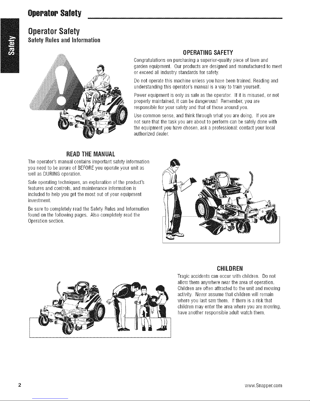
Congratulationson pumhaeinga superior-qualitypieceoflawnand
gardenequipment.Ourproductsaredesignedandmanufacturedtomeet
orexceedallindustrystandardsforsafety.
Do notoperatethismachineunlessyouhavebeentrained.Readingand
understandingthisoperator'smanualisa way totrainyourself.
Power equipment is only as safe as the operator. If it is misused, or not
properly maintained,it can be dangerous! Remember,you are
responsible for your safety and that of those aroundyou.
Use common sense,andthink through what you are doing. If you are
not surethat the task you are about to perform can be safely done with
the equipment you havechosen ask a professional: contact your local
authorized dealer.
READ THE MANUAL
Theoperator's manualcontains important safety information
you needto be awareof BEFOREyou operateyour unit as
well as DURINGoperation.
Safeoperatingtechniques, anexplanationof the product's
features andcontrols, and maintenanceinformation is
included to helpyou get the most out of your equipment
investment.
OPERATINGSAFETY
Be sureto completely readthe Safety Rulesand Information
found on the following pages. Also completely readthe
Operationsection.
CHILDREN
Tragic accidents can occur with children. Do not
allowthem anywherenear the areaof operation.
Childrenareoften attractedto the unit and mowing
activity. Neverassume that children will remain
where you last saw them. Ifthere is a risk that
children may enterthe areawhere you are mowing,
haveanother responsibleadult watch them.
2 www.Snapper.com
20
=154
Operator$alety
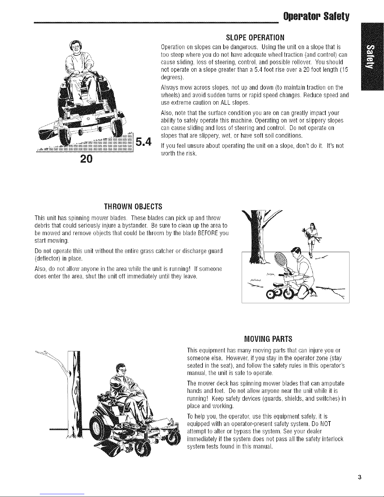
SLOPEOPERATION
Operationonslopescan be dangerous. Using theunit on a slopetbat is
too steepwhere you do not haveadequatewheel traction (and control) can
cause sliding, loss of steering, control, and possiblerollover. You should
not operate on a slope greater than a 5.4 foot rise over a 20 foot length (15
degrees).
Always mow across slopes, not up anddown (to maintaintraction on the
wheels) and avoid sudden turns or rapid speed changes. Reducespeed and
useextremecaution onALL slopes.
Also, notethat the surface condition you are on can greatly impact your
ability to safelyoperatethis machine.Operatingon wet or slippery slopes
can causesliding and loss of steering and control. Do not operate on
slopes that are slippery, wet, or havesoft soil conditions.
If you feel unsureabout operating the unit on a slope, don't do it. It's not
worth the risk.
THROWNOBJECTS
This unit has spinning mower blades. Theseblades can pick up and throw
debris that could seriously injure a bystander. Be sure to clean up the areato
be mowed and remove objects that could bethrown by the blade BEFOREyou
start mowing.
Do not operate this unit without the entiregrass catcher or discharge guard
(deflector) in place.
Also, do not allow anyonein the areawhile the unit is running! If someone
does enter the area.shut the unit off immediately until they leave.
This equipment has many moving parts that can injure you or
someone else. However,if you stay in the operator zone(stay
seated in the seat), and follow the safety rules in this operator's
manual, the unit is safe to operate.
The mower deck hasspinning mower bladesthat can amputate
hands and feet. Do not allow anyonenear the unit while it is
running! Keepsafetydevices (guards, shields, and switches) in
placeandworking.
Tohelpyou, the operator, usethis equipment safely, it is
equippedwith an operator-presentsafety system. Do NOT
attempt to alter or bypassthe system. Seeyour dealer
immediately if the system does not passall the safety interlock
system tests found in this manual.
IVIOVINGPARTS
OperatorSafety
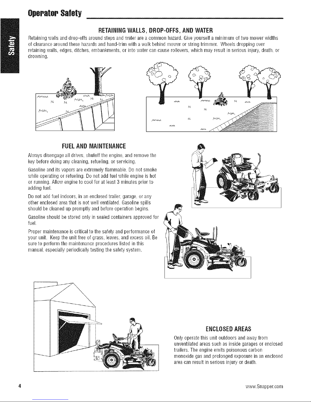
RETAiNiNGWALLS,DROP-OFFS,ANDWATER
Retainingwalls anddrop-offs around stepsand water are a comrnon hazard.Giveyourself a rninimurn of two mower widths
of clearancearound thesehazardsandhand-trim with a walk behind moweror string trimmer. Wheelsdropping over
retainingwalls, edges, ditches, embankments,or intowater car/cause rollovers,which may resultin serious injury,death, or
drowning.
FUELANDIVlAINTENANCE
Always disengageall drives, shutoff the engine, and remove the
key beforedoing anycleaning, refueling, or servicing.
Gasolineandits vapors are extremely flammable. Do not smoke
while operating or refueling. Do not add fuel while engine is hot
or running. Allow engine to cool for at least 3 minutes prior to
adding fuel.
Do not add fuel indoors, in an enclosedtrailer, garage, or any
other enclosed areathat is not well ventilated. Gasolinespills
should be cleanedup promptly and beforeoperation begins.
Gasolineshould be stored only in sealedcontainers approvedfor
fuel.
Proper maintenanceis critical to the safety and performance of
your unit. Keepthe unit free of grass, leaves,and excess oil. Be
sureto perform the maintenance procedures listed in this
manual, especially periodicallytesting the safety system.
i i
ii [i
4 www.Snapper.com
ENCLOSEDAREAS
Only operatethis unit outdoors and away from
unventilatedareassuch as inside garagesor enclosed
trailers. The engine emits poisonous carbon
monoxide gas and prolonged exposure in an enclosed
area can result in serious injury or death.
Operator$a(ety
Readthese safety rules and follow them closely. Failureto obeythese rulescould result in loss of control of unit,
severe personal injury or deathto you, or bystanders, or damageto property or equipment.
This mowinq deck is capableof amputating handsand feet and throwingobjects. Thetriangle _ in text
signifies important cautions or warningswhich must be followed.
GENERAL OPERATION
1. Read,understand,and follow all instructions in the
manualandon the unit beforestarting.
2. Do not put hands or feet nearrotating parts or underthe
machine. Keepclear of the discharge opening at all
times.
3. Onlyallow responsible adults, who are familiar with the
instructions, to operatethe unit (local regulations can
restrict operator age).
4. Clearthe area of objects such as rocks, toys, wire, etc.,
which could be picked upand thrown by the blade(s).
5. Besure the area is clear of other peoplebeforemowing.
Stopthe unit if anyoneentersthe area.
6. Nevercarry I_assengers.
7. Do not mow in reverse unless absolutely necessary.
Always look down and behind beforeandwhile travelling
in reverse.
8. Neverdirect dischargematerial toward anyone. Avoid
discharging material against a wall or obstruction.
Materia/may ricochetback toward the operator. Stop
the blade(s)when crossing gravelsurfaces.
9. Do not operate the machine without the entire grass
catcher, discharge guard (deflector), or other safety
devices in placeandoperational.
10. Slow down before turning.
11. Neverleavearunning unit unattended.Always disengage
the blades(PTO),set parking brake, stop engine,and
remove keysbefore dismounting.
12. Disengageblades(PTO)when not mowing. Shut off
engine and wait for all parts to come to a complete stop
beforecleaningthe machine,removing the grass
catcher, or unclogging the discharge guard.
13. Operatethe machine only in daylight or good artificial
light,
14. Do not operate the unit while underthe influence of
alcohol or drugs.
15 Watch for traffic when operatingnearor crossing
roadways.
16. Useextra carewhen loadingor unloadingthe unit into a
trailer or truck.
17. Always wear eyeprotection when operating this unit.
18. Dataindicatesthat operators, age60 years and above,
are involved in a large percentageof power equipment-
relatedinjuries. Theseoperators should evaluatetheir
ability to operatethe equipment safelyenoughto protect
themselves and others from injury.
19. Follow the manufacturer's recommendationsfor wheel
weights or counterweights.
20. Keepin mind the operator is responsible for accidents
occurring to other people or property.
21. All drivers should seekand obtain professional and
practical instruction.
22. Always wear substantial footwear and trousers. Never
operatewhen barefoot or wearing sandals.
23. Beforeusing, always visually checkthat the bladesand
blade hardwarearepresent, intact, and secure. Replace
worn or damagedparts.
24. Disengageattachments before: refueling, removingan
attachment, making adjustments (unless the adjustment
can be madefrom the operator's position).
25. When the machine is parked,stored, or left unattended,
lowerthe cutting means unless a positive mechanical
lock is used.
26. Beforeleavingthe operator's position for any reason,
engagethe parking brake(if equipped), disengagethe
blades(PTO),stop the engine, andremove the key.
27. To reduce fire hazard,keepthe unit free of grass, leaves,
& excess oil. Do not stop or park over dry leaves,grass.
or combustible materials.
28. It is a violation of California Public ResourceCode
Section4442 to use or operatethe engine on or near
any forest-covered, brush-covered, or grass-covered
land unless the exhaustsystem is equipped with a spark
attester meeting any applicablelocal or state laws.
Otherstatesor federalareas may havesimilar laws.
29. OSHAregulations may require the use of hearing
protection when exposedto sound levelsgreaterthan 85
dBA for an 8 hour time period.
CAUTION
This machine produces sound levels in
excess of 85 dBAat the operator'sear and
cancausehearing lossthroughextended
periodsof exposure.
Wear hearing protectionwhenoperating this
machine.
TRANSPORTING AND STORAGE
1. When transportingthe unit on an open trailer, make sure
it isfacing forward, inthe direction oftravel. If the unit
is facing backwards, wind lift could damagethe unit.
2. Always observe safe refueling and fuel handling
practices when refuelingthe unit after transportation or
storage.
3. Neverstore the unit (with fuel) in an enclosed poorly
ventilated structure. Fuelvapors can travel to an ignition
source such as a furnace, water heater,etc. andcause
an explosion. Fuelvapor is alsotoxic to humans and
animals.
4. Always follow the engine manualinstructions for
storage preparations before storing the unit for both
short and long term periods.
5. Always follow the engine manualinstructions for proper
start-up procedureswhen returning the unitto service.
6. Neverstore the unit or fuel container inside where there
is an open flame or pilot light, such as in a waterheater.
Allow unit to cool before storing.
OperatorSa(ety
SLOPEOPERATION
Slopesare a majorfactor relatedto loss-of-control and tip-
overaccidents,which canresult in severeinjury or death.
Operationon all slopesrequiresextracaution.Ifyou cannot
backup the slopeor ifyou feel uneasyon it. do not operateon
it.
Control of awalk-behindor ride-on machinesliding on a slope
will not beregainedby theapplicationof the brake. Themain
reasonsfor loss of control are: insufficienttire grip onthe
ground,speedtoo fast, inadequatebraking,the type of
machineis unsuitablefor its task, lackof awarenessof the
ground conditions, incorrecthitchingandloaddistribution.
1. Mow across slopes, not up and down.
2. Watch for holes, ruts, or bumps. Uneventerrain could
overturn the unit. Tall grass can hide obstacles.
3. Choosea slow speedso that you will not have to stop or
changespeedswhile on the slope.
4. Do not mow on wet grass. Tires may loosetraction.
5. Avoid starting, stopping, or turning onaslope. If tires
losetraction (i.e. machine stops forward motion on a
slope), disengagethe blade(s) (PTO)anddrive slow off
the slope.
6. Keepall movementon slopes slow andgradual. Do not
makesudden changes in speed or direction, which could
cause the machine to rollover.
7. Useextra care while operating machines with grass
catchers or other attachments;they can affectthe
stability of the unit. Do not use on steepsslopes.
8. Do not try to stabilizethe machine by putting your foot
on the ground (ride-on units).
9. Do not mow near drop-offs, ditches, or embankments.
The mower could suddenly turn over if a wheel is over
the edgeof a cliff or ditch, or if an edgecavesin.
10. Do not use grass catchers on steepslopes.
11. Do not mow slopes if you cannot back up them.
12. Seeyour authorizeddealer/retailerfor recommendations
of wheel weights or counterweights to improve stability.
13. Removeobstaclessuch as rocks, tree limbs, etc.
14. Useslow speed.Tiresmay losetraction on slopes even
though the brakes are functioning properly.
15. Do not turn on slopes unless necessary,andthen, turn
slowly and gradually uphill, if possible. Nevermow
down slopes.
TOWEDEQUIPMENT(RIDE-ONUNITS)
1. Tow only with a machinethat hasa hitch designedfor
towing. Do not attachtowed equipment except atthe
hitch point.
2. Follow the manufacturer's recommendationsfor weight
limit for towed equipmentandtowing on slopes. See
.WARNiNG
Never operate on slopes greater than 15° whichisa
rise of 5.4 feet (1,6 m) vertically in 20 feet (6 m)
hoNzontally.
Select slow ground speedbeforedriving onto slope.
Useextra cautionwhen operatingon slopeswith rear-
mounted grass catchers.
Mow across theface of slopes, not up and down,use
caution when changingdirections and DO NOTSTART
ORSTOPONSLOPE.
attaching a trailer under OPERATION.
3. Neverallow children or others in or ontowed
equipment.
4. Onslopes, the weight of the towed equipment may
cause loss of traction and lossof control.
5. Travelslowly and allow extra distanceto stop.
6. Do not shift to neutral and coast down hill.
CHILDREN
Tragicaccidentscanoccurif the operator is notalertto the
presenceof children.Childrenareoftenattractedto the unit
andthe mowing activity. Neverassumethat childrenwill
remainwhereyou lastsawthem.
1. Keepchildren out of the mowing areaandunderthe
watchful care of another responsible adult.
2. Bealert and turn unit off if children enter the area.
3. Beforeandduring reverseoperation, look behind and
down for small children.
4. Nevercarry children, evenwith the blade(s)off. They
may fall off and be seriously injured or interfere with
safe unit operation. Childrenwho havebeen given rides
in the past may suddenly appear in the mowing areafor
another ride and be run overor backedover by the
machine.
5. Neverallow children to operatethe unit.
6. Useextra care when approachingblind corners, shrubs.
trees, or other objectsthat may obscure vision.
EMISSIONS
1. Engineexhaustfrom this product contains chemicals
known, in certain quantities, to cause cancer, birth
defects, or other reproductive harm.
2. Lookfor the relevant Emissions Durability Period and Air
Index information onthe engine emissions label.
IGNITIONSYSTEM
1. Thisspark ignitionsystem complies with Canadian
ICES-O02.
6 www.Snapper.com
OperatorSafety
SERVICEAND MAINTENANCE
Safe Handling ofGasoline
1. Extinguishall cigarettes,cigars, pipes, and other sources
of ignition.
2. Useonly approvedgasolinecontainers.
3. Neverremove the gas cap or add fuel with the engine
running. Allow the engineto cool before refueling.
4. Neverfuel the machine indoors.
5. Neverstore the machine or fuel container where there is
an open flame, spark, or pilot light such as near a water
heateror other appliance.
6. Neverfill containers insideavehicle or on atruck bed
with a plastic bed liner. Always placecontainers on the
ground away from your vehicle before filling.
7. Removegas-powered equipment from the truck or trailer
and refuel it on the ground. If this is not possible, then
refuelsuch equipment on a trailer with a portable
container, rather than from a gasoline dispenser nozzle.
8. Keepnozzlein contact with the rim of the fuel tank or
container opening at all times until fueling is complete.
Do not use a nozzlelock-opendevice.
9. If fuel is spilled on clothing, changeclothing
immediately.
10, Neverover-fill the fuel tank. Replacegas cap and tighten
securely.
11, Useextra care in handling gasoline and other fuels. They
are flammable and vapors are explosive.
12, If fuel is spilled, do not attempt to start the engine but
move the machine awayfrom the area of spillage and
avoid creating anysource of ignition until fuel vapors
havedissipated.
13, Replaceall fuel tank caps and fuel container caps
securely.
Service & Maintenance
1. Neverrun the unit in anenclosedareawhere carbon
monoxide fumes may collect.
2. Keepnuts andbolts, especially bladeattachment bolts.
tight and keepequipment ingood condition.
3. Nevertamper with safety devices. Checktheir proper
operation regularly and make necessaryrepairs if they
are not functioning properly.
4. Keepunit free of grass, leaves,or other debris build-up.
Cleanup oil or fuel spillage, and removeanyfuel-soaked
debris. Allow machineto cool before storage.
5. If you strike an object, stop andinspect the machine.
Repair,if necessary,before restarting.
6. Nevermake adjustments or repairs with the engine
running.
7. Checkgrass catchercomponents and the discharge
guard frequently and replacewith manufacturer's
recommendedparts, when necessary.
8. Mower blades are sharp. Wrap the blade or wear
gloves, and useextracaution when servicing them.
9. Checkbrake operation frequently. Adjust and service as
required.
10. Maintain or replacesafety and instructions labels,as
necessary.
11. Do not remove the fuel filter whenthe engine is hot as
spilled gasoline may ignite. Do not spreadfuel line
clamps further than necessary. Ensureclamps grip
hosesfirmly over the filter after installation.
12. Do not use gasolinecontaining METHANOL,gasohol
containing more than 10% ETHANOL,gasolineadditives,
or white gas becauseengine/fuel system damagecould
result.
13. If the fuel tank must bedrained, it should be drained
outdoors.
14. Replacefaulty silencers/mufflers,
15. Maintain or replacesafety and instruction labelsas
necessary.
16. Useonly factory authorized replacementpartswhen
making repairs.
17. Always comply with factory specifications on all settings
and adjustments.
18. Onlyauthorizedservice locations should be utilized for
major service and repair requirements.
19. Neverattempt to make major repairs on this unit unless
you havebeenproperlytrained. Improper service
procedures canresult in hazardous operation, equipment
damageandvoiding of manufacturer's warranty.
20. On multiple blade mowers, take care as rotating one
bladecan cause other bladesto rotate.
21. Do not change engine governor settings or over-speed
the engine. Operatingthe engine at excessivespeedcan
increasethe hazardof personalinjury.
22. Disengagedrive attachments,stop the engine, remove
the key,and disconnectthe spark plug wire(s) before:
clearing attachment blockages and chutes, performing
service work, striking an object, or if the unit vibrates
abnormally. After striking an object, inspect the machine
for damageand make repairs before restarting and
operatingthe equipment.
23. Neverplace handsnearthe moving parts, such as a
hydro pump cooling fan, when the tractor is running.
(Hydro pump cooling fans are typically located on top of
the transaxle),
24. Units with hydraulic pumps, hoses,or motors:
WARNING:Hydraulicfluid escaping under pressure may
havesufficient force to penetrateskin and causeserious
injury. If foreign fluid is injected into the skin it must be
surgically removed within a few hours by a doctor
familiar with this form of injury or gangrenemay result.
Keepbody and hands awayfrom pin holes or nozzles
that eject hydraulicfluid under high pressure. Usepaper
or cardboard, and not hands,to search for leaks. Make
sure all hydraulic fluid connections are tight and all
hydraulic hoses and lines are in good condition before
applying pressureto the system. If leaks occur, havethe
unit serviced immediately byyour authorized dealer.
25. WARNING:Stored energydevice. Improper release of
springs can result inserious personal injury. Springs
should be removed by an authorizedtechnician.
26. Models equipped with an engine radiator: WARNING:
Storedenergy device. To prevent serious bodily injury
from hot coolant or steam blow-out, neverattempt to
removethe radiator capwhile the engine is running.
Stopthe engine andwait until it is cool. Eventhen. use
extreme care when removing the cap.

,OperstorSslety
Safety Decals
Thisunithasbeendesignedandmanufacturedto provide
youwiththesafetyandreliabilityyouwouldexpectfroman
industryleaderin outdoorpowerequipmentmanufacturing.
Although reading this manualand the safety instructions it
contains will provideyou with the necessary basic
knowledge to operatethis equipment safely and effectively,
we have placedseveralsafetylabelson the unit to remind
you of this important information while you are operating
your unit.
All DANGER,WARNING, CAUTIONand instructional
messageson your rider and mower should be carefully read
and obeyed. Personalbodily injury can result when these
instructions are not followed. The information is for your
safety and it is important! Thesafetydecalsbelow are on
your rider and mower.
If any of these decals are lost or damaged, replacethem at
once. Seeyour local dealerfor replacements.
Theselabelsare easilyapplied and will act as a constant
visual reminderto you, and others who mayusethe
equipment,to follow the safety instructions necessaryfor
safe,effective operation.
1
4
\
\
3
_5
4
5
8 www.Snapper.com
6 2
SafetyInterlockSystem
this unit isequippedwith safety interlockswitches. These
;afetysystems arepresentfor your safety,do not attempt
:o bypass safety switches, andnevertamper with safety
Jevices. Checktheir operation regularly.
Operator$alety
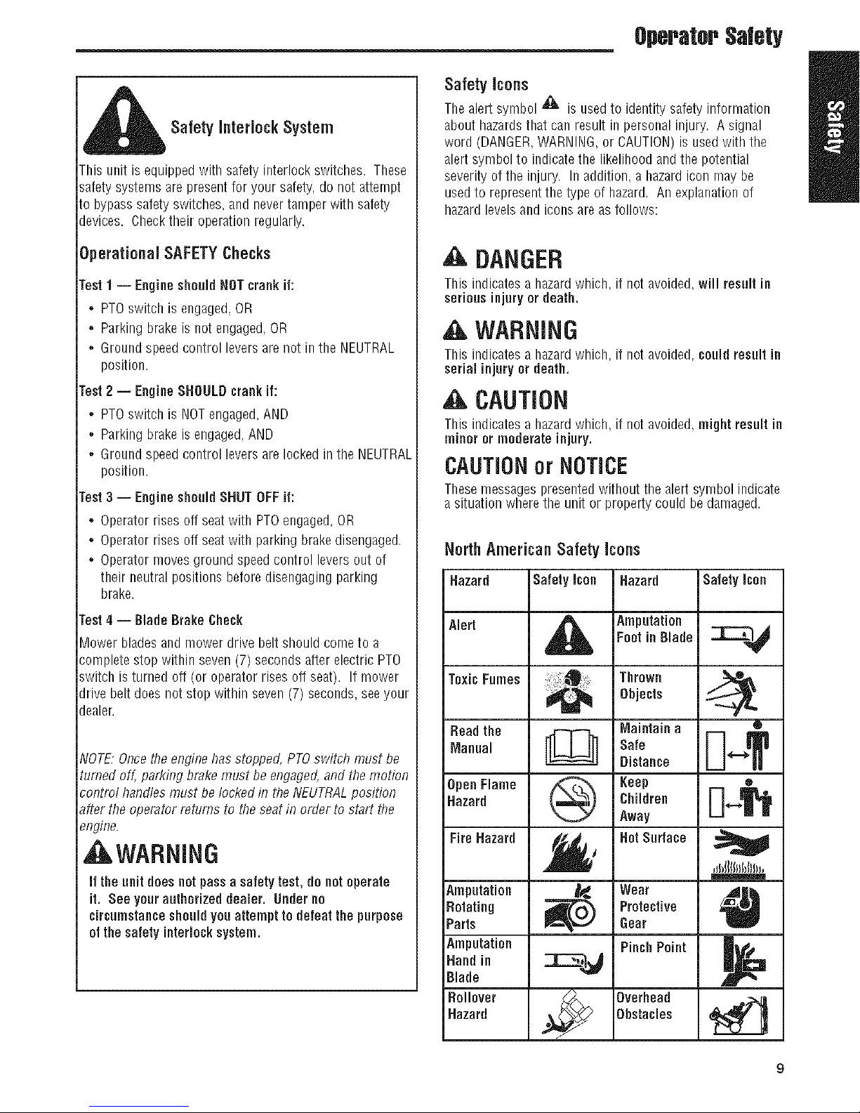
Safety icons
Thealert symbol '_ isusedto identitysafety inforrnation
about bazardsthatcan result in personalinjury. A signal
word (DANGER,WARNING,or CAUTION)is usedwitb tbe
alert symbol to indicatethe likelihood and the potential
severity of the injury. In addition, a hazardicon may be
usedto represent the type of hazard. An explanation of
hazardlevelsandicons are asfollows:
Operational SAFETYChecks
Fast1 -- Engine should NOTcrank if:
,, PTOswitch is engaged,OR
,, Parking brakeis not engaged,OR
,, Ground speed control levers are not in the NEUTRAL
position.
Fast2 -- EngineSHOULDcrankit:
,, PTOswitch is NOTengaged,AND
,, Parking brakeis engaged,AND
,, Ground speed control levers are locked in the NEUTRAL
position.
Fast3 -- Engineshould SHUTOFFif:
,, Operator rises off seatwith PTOengaged, OR
,, Operator rises off seatwith parking brake disengaged.
,, Operator movesground speedcontrol levers out of
their neutral positions before disengagingparking
brake.
rest4 -- Blade Brake Check
_ower bladesand mower drive belt should come to a
:;ompletestop within seven (7) seconds after electric PTO
;witch is turned off (or operator rises off seat). If mower
Jrive belt does not stop within seven (7) seconds,seeyour
Jealer.
_IOTE:Oncethe enginehas stopped, PTOswitch must be
turned off, parking brake must be engaged,and the motion
_ontml handlesmust be locked in the NEUTRALposition
_fter the operator returns to theseatin order to start the
9ngine.
,Ji WARNING
if theunit does notpassa safetytest, do notoperate
it. See yourauthorized dealer. Underno
circumstanceshould you attempt to defeat the purpose
of the safety interlocksystem.
DANGER
This indicatesa hazardwhich, if not avoided, will resultin
seriousinjury or death.
,A WARNING
This indicatesa hazardwhich, if not avoided, could resultin
serial injury or death.
CAUTION
This indicatesa hazardwhich, if not avoided, might result in
minor or moderate injury.
CAUTIONor NOTICE
Thesemessages presentedwithout tbe alert symbol indicate
a situation wherethe unit or property could be damaged.
NorthAmerican Safety Icons
Hazard
Alert
ToxicFumes
Read the
Manual
OpenFlame
Hazard
Fire Hazard
Amputation
Rotating
Parts
Amputation
Hand in
Blade
Rollover
Hazard
Safety icon
®
Hazard
Amputation
Foot in Blade
Thrown
Objects
Maintain a
Safe
Distance
Keep
Children
Away
Hot Surface
Wear
Protective
Gear
Pinch Point
Overhead
Obstacles
Safety icon
®
O
,JbIIIIId)()in,
O
9

.FeaturesandControls
Featuresand Controls
Identification Numbers
Whencontactingyourauthorized dealer for replacement
parts, service, or informationyou MUSThavethese
numbers.
Recordyour part number, serial number and engine serial
numbers in the space provided on the inside front cover for
easyaccess. These numbers can be found in the locations
shown in Figure1.
NOTE,Forlocationof engineidentification numbers, refer to
theengineowner's manual.
Figure 1. IdentificationNumbers
A. Identification Tag
10 www.Snapper.com
FesturesandCefltrols
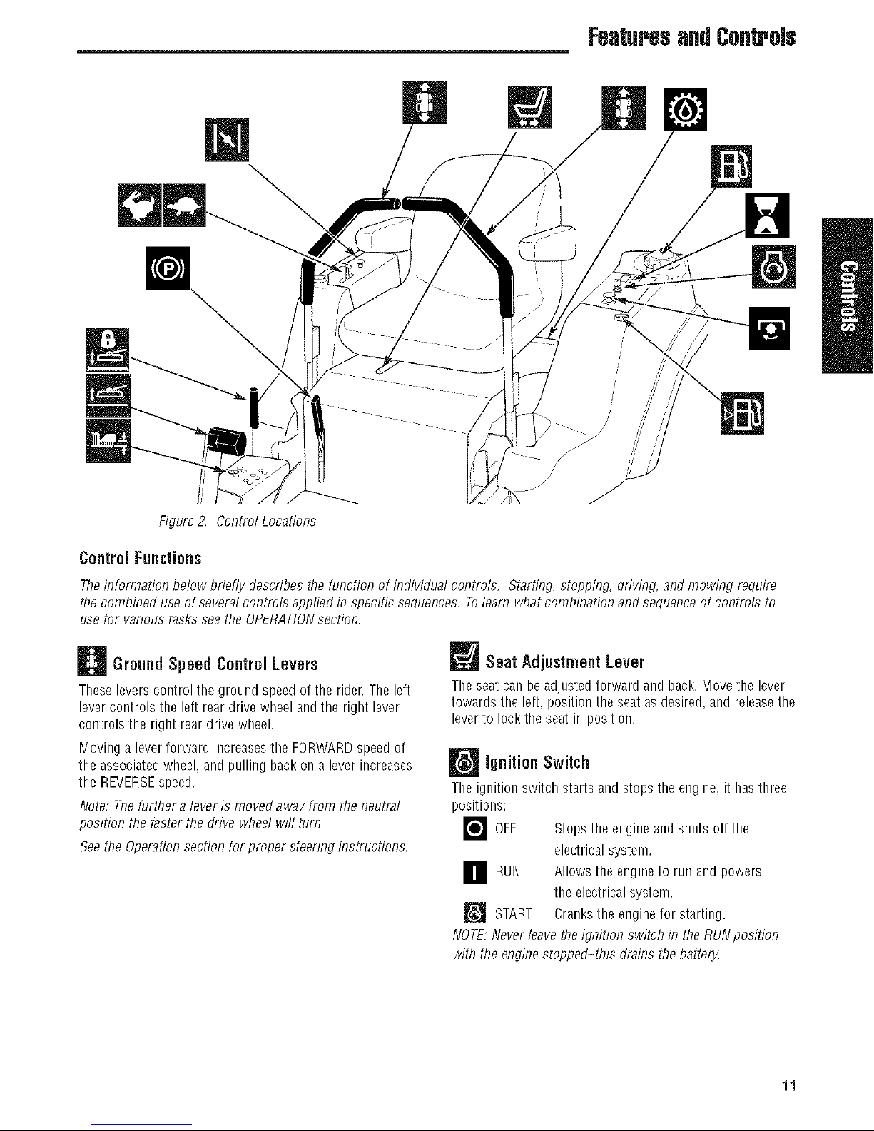
Figure2, Control Locations
Control Functions
Theinformation below briefly describes the timction of individual controls. Starting, stopping, driving, andmowing require
thecombined use of several controls applied in specific sequences. Tolearn whatcombination and sequenceof controls to
usefor various tasks seethe OPERATIONsection.
Ground Speed Control Levers
Theseleverscontrol the ground speed of the rider, The left
lever controls the left reardrive wheel andthe right lever
controls the right rear drive wheel.
Moving a leverforward increasesthe FORWARDspeed of
the associatedwheel,and pulling back on a lever increases
the REVERSEspeed.
Note: Thefurther alever is moved away from the neutral
position the faster the drive wheel will turn.
Seethe Operationsection for proper steering instructions.
Seat Adjustment Lever
Theseatcan be adjusted forward and back.Movethe lever
towards the left, position the seat as desired, and releasethe
leverto lock the seat in position.
ignition Switch
The ignition switch starts and stops the engine, it hasthree
positions:
r_OFF
RUN Allows the engineto run and
_'_ START Cranksthe enginefor starting.
NOTE.Neverleavethe ignition switch in the RUNposition
with the enginestopped-ttiis drains thebattery,
Stops the engineand shuts off the
electrical system.
powers
the electrical system.
11

Features& Controls
ParkingBrake
DISENGAGE Releasesthe parking brake.
m ENGAGE Locks the parking brake.
Pullthe parking brake leverupto engagethe parking brake.
Pushthe lever down to disengage the parking brake. NOTE,
Tostart the unit theparking brakemust be engaged.
PTO (Power Take Off) Switch
The PTOswitch engagesand disengagesthe mower. Pull UP
on the switch to engage,and push DOWNto disengage.
m_ Deck Lift Pedal, Cutting Height
='='='_='-"_Adjustment Pin & Deck Lift Lock
Lever
Thesecontrol the cutting height of the mower deck.
Depressthe pedal until it locks into the 4-1/2" (11,47 cm)
position. Placethe adjustment pin in the desired cutting
height and releasethe lift lock lever.
Fuel Tank Cap
Toremovethe cap, turn counterclockwise.
Fuel LevelGauge
Displays the fuel level in the tank.
LL_JTransmission Oil Fill
This unit is equipped with two transmission oil reservoirs.
Thetransmission oil reservoirs arelocated beneaththe
operator's seat and in front of the engine. Transmission oil
is added through the transmission oil reservoirs. It also
servesas extra holding capacity as thetransmissions heat
up andthe oil expands. SeeCHECKTRANSMISSIONOIL
LEVELfor oil levelcheckandfill procedures.
Throttle Control
Thethrottle controls engine speed, Movethe throttle
forward to increaseenginespeedand backto decrease
engine speed. Always operateat FULLthrottle,
_ Choke
Closethe choke for cold starting. Openthe choke oncethe
engine starts. A warm engine may not requirechoking. Pull
the knob UP to close the choke. Pushto knob DOWNto
open the choke.
B Hour Meter / Maintenance Reminder
Measuresthe time of the PTObeing engaged, The hour
meter measuresthe number of hoursthe PTO hasbeen
engaged. The hour meter will flash an initialoil change
indicator at 5 hours, and a lubrication reminder every 50
hours. Thesereminders display for approximately two
hours andwill automatically reset themselves.
Note: Thehour meter will register the passageof time only
whenthe PTOis engaged. Thehour meter has a self
containedpower source so the total hours are always
visible.
12 www.Snapper.com
Operation
Operation
GeneralOperatingSafety
Beforefirst time operation:
,, Besure to read all information in the Safety and
Operationsections before attempting to operate this
tractor and mower.
,, Becomefamiliar with all of the controls and how to stop
the unit.
,, Drive in an open areawithout mowing to become
accustomedto the unit.
WARNING
Neverallow passengers to ride an the unit.
Beforeleavingthe operator'spositionfor any reason,
engage the parking brake, disengage the PTO,stopthe
engine and remave thekey.
Toreducefire hazard, keepthe engine, tractorand
mower free of grass, leavesand excessgrease. Donot
stopor park tractor over dry leaves, grass or
combustiblematerials.
Gasoline is highly flammable and must be handled
with care. Neverfill the tankwhen the engineis still
hotfrom recent operation.Donet allow open flame,
smokingor matches in the area. Avoid over-fillingand
wipe up any spills.
WARNING
AWARNING
Never operateon slopesgreater than (15°) whichisa
rise of5.4 feet (1,6 m) vertically in 20 feet (607 cm)
horizontally.
Select slow ground speedbeforedriving ontoa slope.
Useextracautionwhenoperatingonslopeswith a
rear-mountedgrass catcher.
Mow across theface ofslopes, net up anddown, use
cautionwhenchangingdirections and DO NOTSTART
ORSTOPONSLOPE.
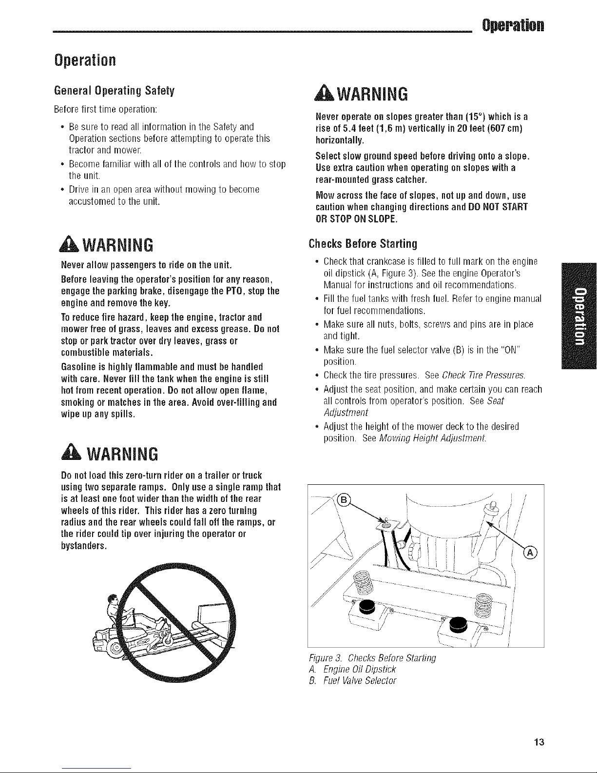
Checks Before Starting
,, Checkthat crankcaseis filled to full mark on the engine
oil dipstick (A, Figure3). Seethe engine Operator's
Manualfor instructions and oil recommendations.
,, Fill the fuel tanks with fresh fuel. Referto engine manual
for fuel recommendations.
,, Makesure all nuts, bolts, screws andpins are in place
and tight.
,, Makesure the fuel selector valve (B) is in the "ON"
position.
,, Checkthe tire pressures. See Check TirePressures.
,, Adjust the seat position, and make certain you canreach
all controls from operator's position. SeeSeat
Adjusflnent
,, Adjust the height ofthe mower deck to the desired
position. SeeMowing Height Adjustment.
Donotloadthis zero-turnrider on a trailer or truck
using two separateramps. Onlyuse a singlerampthat
isat least onefootwiderthan the width of the rear
wheels of this rider. Thisriderhasa zero turning
radius and therear wheels couldfail offthe ramps, or
the rider couldtip over injuringthe operatoror
bystanders.
®
Figure3. ChecksBefore Starting
A. Engine0il Dipstick
B. Fuel ValveSelector
13

Operation
CheckTire Pressures
Tire pressure should bechecked periodically,and
maintained at the levels shown in the chart. Note that these
pressures may differ slightly from the "Max Inflation"
stamped on the side-wall of the tires. The pressures shown
provide proper traction, improve cut quality, and extendtire
life.
Tire Pressure
Front 40 psi (276 bar)
Rear 15 psi (1,03 bar)
Seat Adjustment
See Figure5. The seat can be adjusted forward and
backward. Movethe lever towards the left, position the seat
asdesired, and releasethe lever to lock the seat into
position.
Figure4. Checking TirePressure
Figure5. SeatAdjustment
A. SeatAdjustment Lever
14 www.Snapper.com

Mowing HeightAdjustment
Thecutting height adjustment pin (A, Figure6) controls the
mower cutting height. Thecutting height is adjustable
between 1-1/2" (3,37 cm) and 4-1/2" (11,47 cm) in 1/4"
(0,64 cm) increments.
1. Depressthe deck lift foot pedal (B) until it locks into the
4-1/2" (11,47 cm) position.
2. Placethe cutting height adjustment pin in the desired
cutting height.
3. Depressthe deck lift foot pedalthen pushthe lock lever
(C)toward the right to releasethe lock.
4. Releasethe deck lift foot pedal until it comes to rest
against the cutting height adjustment pin.
Foot PedalAdjustment
OperaUofl
Figure 6, Mowing Height Adjustment
A. Cutting Height Adjustment Pin
B, Deck Lift Foot Pedal
C. Deck Lift Lock/ever
Thedecklift foot pedalcan be adjusted to accommodatethe
operator's height for optimal comfort.
Toadjust pedal position:
1. Removethe foot pedal (A, Figure7) from the pedal
mount tab (B).
2. Removethe pedal mount hardware(C) and rotate the
tab 180 degrees.
3. Reinstallthe pedal mount hardware andtighten securely.
4. Reinstallthe foot pedalon the pedal mount tab in the
proper orientation as shown in Figure7.
Figure 7. Foot PedalAdjustment
A. Deck Lift FootPedal
B, Pedal Mount Tab
C. PedalMount Hardware
D. Optional Position
15

Operation
Starting the Engine
AWARNING
ifyoude net understandhow a specificcontrol
functions, or havenotyetthoroughlyread the
FEATURES& CONTROLSsection, do sonow.
DoNOTattempt to operatethetractorwithoutfirst
becoming familiar with the locationand function ofALL
controls.
1. While sitting in the operator's seat,engagethe parking
brakeby pulling the parking brake lever up, make sure
the PTOswitch is disengaged (presseddown fully) and
the ground speedcontrol levers are locked in the
NEUTRALposition.
2. NOTE:A warm enginemay not require choking.
Setthe enginethrottle control to FULLthrottle position,
Thenfully close the choke by pulling the knob OUTfully.
3. Insert the key into the ignition switch andturn it to
START.
4. After the engine starts, gradually open the choke (push
knob down fully). Reduceto half throttle speedand
allow to warm up.
Warm up the engineby running it for at leasta minute
before engaging the PTOswitch or driving the riden
5. After warming the engine,ALWAYSoperate the unit at
FULLTHROTTLEwhen mowing.
In the eventof an emergencythe enginecan he stopped
hy simply turningthe ignition switch to STOP. Use this
method only in emergencysituations. Fornormal engine
shut down follow theprocedure given in STOPPINGTHE
RIDER,
Pushingthe Rider By Hand
NOTICE
DO NOT TOW BINDER
Towingthe units will causetransmissiondamage. De
notuse another vehicle to pushor pull this unit.
1. Disengagethe PTO,engagethe parking brake,turn the
ignition OFEand remove the key.
2. Locatethe transmission releaselevers(A, Figure 8)
located underneaththe front ofthe fuel tanks.
3. Pull both transmission releaseleversback and down so
that they lock in the disengaged (free-wheelposition)
(C).
4. Disengagethe parking brake.
Thetractor can now be pushed by hand.
5. After moving the tractor, re-engagethe transmissions by
pulling thetransmission releaseleversupand pushing
them forward to the engaged (drive) position (B).
Stopping the Rider
1. Returning the ground speedcontrol leversto the middle
position will stop rider movement. Pivot the levers
outward and lock them in NEUTRAL.
2. Disengagethe PTOby pushing down on the PTOswitch.
3. Engagethe parking brake by pulling the handleup until
it locks into position.
4. Move thethrottle control to mid-throttle position and
turn the ignition keyto OFE Removethe key.
16 www.Snapper.com
Figure8. Transmission ReleaseLevers (LH shown)
A. TransmissionReleaseLever
B, EngagedPosition (Drive Position)
C. DisengagedPosition (Free-wheelPosition)

Operatiofl
Zero Turn Driving Practice
The lever controls of the Zero Turn rider are responsive, and
learning to gain a smooth and efficient control of the rider's
forward, reverse,andturning movements will take some
practice.
Spending some time going through the maneuvers shown
and becoming familiar with how the unit accelerates,travels.
and steers -- beforeyou beginmowing --is absolutely
essentialto getting the most out of the Zero Turn rider.
Locatea smooth, fiat area ofyour lawn -- one with plenty
of room to maneuver. (Clearthe area of objects, peopleand
animals before you begin.) Operatethe unit at mid-throttle
during this practicesession (ALWAYSoperateat full throttle
when mowing), and turn slowly to preventtire slippage and
damageto your lawn.
Wesuggest you begin with the Smooth Travelprocedureto
the right, and then advancethrough the forward, reverse.
and turning maneuvers.
You must releasethe parking brake prior to moving the
ground speedcontrol levers inward.
Smooth Travel
The lever controls of the
ZeroTurn rider are
responsive.
The BESTmethod of
handling the ground
speedcontrol levers is in
three steps -- as shown
in Figure9.
FIRSTplaceyour hands
onto the levers as shown.
SECOND,to go forward
gradually push the levers
forward with your palms.
THIRD,to speedup move
the levers farther
forward. Toslow down
smoothly, slowly move
the levers toward neutral.
ForwardTravelPractice
Graduallymove both ground speedcontrol levers--evenly
FORWARDfrom neutral. Slow down and repeat.
NOTE:Straight forward travel takespractice, If necessad4
top speed canbe balance-adjusted-- seethe Speed
BalancingAdjusflnent in theAdjustments section near the
back of this manual.
Forward
Travel
Figure9. Move Control
Levers Gradually
Reverse Travel Practice
LOOKDOWN& BEHIND,then gradually move both ground
speedcontrol levers evenly BACKfrom neutral. Slow down
and repeat.
NOTE:Practicebacking upfor severalminutes before
attempting to do so near objects. Therider turns sharply in
reverseas well as forward, and backing up straight takes
practice.
Reverse
Travel
' / \
Figure 10. Forward Travel Figure 11. ReverseTravel
17
Operation
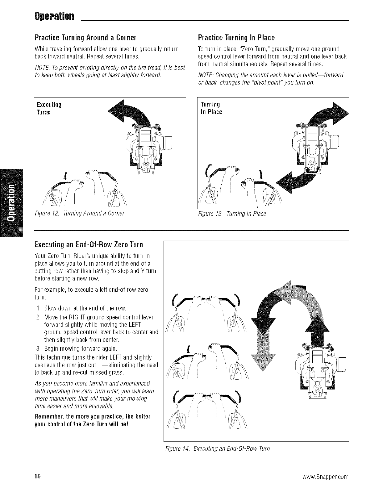
Practice Turning Around a Corner
WNletravelingfarwardallawanelevertograduallyreturn
backtowardneutral.Repeatseveraltimes.
NOTE,"Toprevent pivoting directly an the fire tread, it is best
to keep bath wheelsgoing at least slightly forward.
Executing
Turns
Figure 12, TurningAmund a Corner
PracticeTurningin Place
Toturn in place, "Zero Turn," gradually mave ane graund
speedcontrol leverforward from neutral and one lever back
from neutral simultaneously. Repeatseveraltimes.
NOTE:Changingtheamount eachleveris pulled--farward
ar back, changes the "pivot paint" yau turn an.
Turning
In-Place
Figure 13. Turningin Place
Executingan End-Of-RowZero Turn
Your ZeroTurn Rider'sunique ability to turn in
placeallows you to turn aroundat the end of a
cutting row ratherthan havingto stop and Y-turn
before starting a new row.
Forexample,to executea left end-of row zero
turn:
1. Slow down at the end of the row.
2. Move the RIGHTground speedcontrol lever
forward slightly while moving the LEFT
ground speed control leverbackto center and
then slightly backfrom center.
3. Begin mowing forward again.
This technique turns the rider LEFTand slightly
overlaps the row just cut --eliminating the need
to back up and re-cut missed grass.
Asyou become more familiar and experienced
with operating theZero Turnrider,you will learn
more maneuvers that will makeyour mowing
time easierandmore enjoyable.
Remember,the mare yau practice, the better
yourcontroloftheZero Turnwili be!
18 www.Snapper.com
Figure 14. Executingan End-Of-Raw Turn

Operatio.
Mowing
1. Engagethe parking brake. Make surethe PTOswitch is
disengaged,the ground speed control leversare locked
in the NEUTRALposition andthe operator is on the seat.
2. Start the engine (see Starting The Engine).
3. Setthe mower cutting height (see Mowing Height
Adjustment).
4. Setthe throttle to FULL.
5. Engagethe PTOby pulling up on the PTOswitch.
6. Begin mowing. See Mowing Recommendationsfor tips
on mowing patterns, lawn care, and trouble shooting
information.
7. When finished, shut off the PTOby pushingthe PTO
switch down completely..
8. Stopthe engine (see Stopping TheRiderand Engine).
Mowing Recommendations
Severalfactors canaffect how well your machine cuts grass,
Following proper mowing recommendationscan improve
the performance and life of your machine.
Heightof Grass
Often cutting height is a matter of personal preference.
Typically,you should mow the grass when it is is between
three and five inches high. The proper cutting height range
for a specific lawn will depend upon several factors,
including the type of grass,the amount of rainfall, the
prevailing temperature, and the lawn's overallcondition.
Cutting the grass too short causesweak,thin grass plants,
which are easily damaged by dry periods and pests. Cutting
too short is often more damaging than allowing the grass to
be slightly higher.
Letting grass grow a bit longer--especially when it is hot
and dry--reduces heat build-up, preservesneededmoisture
and protects the grass from heatdamageand other
problems. However,allowing grassto grow too high can
causethin turf and additional problems.
Cutting off too much at one time shocksthe plant's growth
system and weakensthe grass plants. A good rule of thumb
is the 1/3 role:to cut nomore thanonethirdof the grass
height, and nevermare than 1 inch at a time.
Theamount of grass you are ableto cut in one pass is also
effected by thetype of mowing system you are using (for
example,broadcasting with side discharge decks can
process a much larger volume of grassthan mulching
does).
I
Figure 15. Proper Cutting Height
Tall GrassRequires IncrementalCutting
Forextremelytall grass, set the cutting heightat maximum
for the first pass, andthen reset it to the desired height and
mow a second or third time.
Don't coverthe grass surface with a heavy layerof
clippings. Consider using a grass collection system and
starting a compost pile.
Cut HereOn
First Pass Cut Here
_j/, Pass
Figure 16. IncrementalCutting
__ On Second
19

Operation
WhenandHowOften to Mow
Thetime of day and condition of the grass greatly affect the
results you'll get when mowing. For the best results, follow
these guidelines:
1. Mow when the grass is betweenthree and five inches
high.
2. Mow with sharp blades. Short clippings of grass one
inch or shorter decompose more quickly than longer
blades.Sharp mower bladescutgrass cleanly and
efficiently, preventing frayed edgeswhich harmthe
grass.
3. Mow at time of day whenthe grassis cool and dry. Late
afternoon or early evening often providethese ideal
mowing conditions.
4. Avoid mowing after rain or even heavy dew,and never
mulch when the grass is wet (moist grass does not
mulch well, and clumps beneaththe mower deck).
Mowing Patterns
Always start mowing on a smooth, levelarea.
Thesizeandtype of areato be mowedwill determine the
best mowing patternto use.Obstructions such astrees,
fencesand buildings, and conditions such asslopes and
grades must also be considered.
1. Cut long straight strips overlapping slightly.
2. Where possible, changepatterns occasionallyto
eliminate matting, graining or a corrugated appearance.
3. Foratruly professional cut, mow across the lawn in one
direction, then recutthe lawn by mowing perpendicular
to the previous cut.
Note:Alwaysoperate the engine at full throttle when
mowing,
If you hearthe engine slowing down, you are mowing too
fast--using a slower ground speedwill improve the cutting
efficiency of the blades and prevents many common cutting
problems. Usean appropriate ground speed for the
thickness and height of the grass you arecutting (3rd gear
or slower for manualgear models). If you hearthe engine
slowing down you are mowing too fast. useaslower ground
speed.
Wherepossible, make one or two passes around the outside
of the areadischarging the grass INTOthe lawn to keep the
cut grass off fencesand walks.
Theremainderof the mowing should be done in the
opposite direction so that the clippings aredispersed OUT
onto the areaof lawn previously cut.
Mowing Methods
ProperBroadcastMowing
Broadcasting, or side-discharging, dispersesfine clippings
evenly overthe entire lawn. Many golf courses use this
method. Your mower has a deep dish deck to allow freer
circulation of clippings so they are broadcast evenlyover the
lawn.
Engine Speed & GroundSpeedfor Broadcasting
Always operatethe engine at full throttle when mowing. If
you hearthe engine slowing down, you are mowing too
fast--using a slower ground speedwill improve the cutting
efficiency of the blades and prevents many common cutting
problems.
ALWAYSusean appropriate ground speedfor the thickness
and height of the grass you arecutting (3rd gear or slower
for manualgear models). If you hearthe engine slowing
down you are mowing too fast, usea slower ground speed.
20 www.Snapper.com
How Much Grassto CotOff When Broadcasting
Mow when the grass is 3-5 inches long. Do not cut the
grass shorter than 2 to 2-1/2 inches. Do not cut off more
that 1 inch of grass in a single pass

Operatiofl
ProperMulching
Mulching consists of a mower deck which cuts and recuts
clippings into tiny particles and which then blowsthem
down INTOthe lawn. Thesetiny particles decomposerapidly
into by-products your lawn can use. UNDERPROPER
CONDITIONS,your mulching mower will virtually eliminate
noticeable clippings on the lawn surface.
NOTE:When mulching under heavycutting conditions, a
rumbling sound maybe presentand is normal.
Mulching RequiresEXCELLENTMowing Conditions
Mulching mowers cannot function properly if the grass is
wet, or ifthe grass is simply to high to cut, Evenmorethan
normal mowing, mulching requiresthat the grass be dry
and the the appropriate amount is cut.
Do not use the mower as a mulching mower during the first
two or three mowings in the spring. The long grass blades,
quick growth, and often wetter conditions are more suitable
for broadcasting (side-discharging) or grass bagging
operation.
EngineSpeed & GroundSpeedfor Mulching
Use full enginethrottle matched with a slow ground speed
so that clippings will befinely cut. Groundspeedwhile
mulching should be HALFof the speedthat would be used
when broadcasting (side discharging) undersimilar
conditions. Since mulching requires more horsepowerthan
broadcasting, using a slower ground speedis vitally
important for proper mulching operation.
Now Much Grassto Mulch
Attaching A Trailer
The maximum weight of atowedtrailersbould be lesstban
200 Ibs (91kg). Securethe trailer with a appropriately sized
clevis pin (A, Figure 18) and clip (B).
Excessivetowed loadscan cause loss of traction and loss of
control on slopes. Reducetowedweight when operating on
slopes. The surface being driven on greatly impactstraction
and stability. Wet or slippery surfaces can greatly reduce
traction and the ability to stop or turn. Carefullyevaluatethe
surface conditions before operatingthe unit and trailer, and
neveroperate on slopes greaterthan 10°. See SLOPE
OPERATIONand TOWEDEQUIPMENTin the safety section
of this manualfor additional safety information.
o/
®
The best mulching action typically results from cutting only
the top 1/2 inch to 3/4 inch of grass blade.This provides
short clippings which decompose properly (much more
quickly than longer clippings). The ideal cutting height will
vary with climate, time of year,and quality of your lawn.We
recommend that you experimentwith both the cutting height
and ground speed until you achievethe bestcut. Start with a
high cutting height and using progressively lower settings
until you find a cutting height that is matchedto your
mowing conditions and preferences.
Figure 17. Mulching Action
20' (6m)
Figure 18. TrailerWeightRecommendations
A. Clevis Pin
B. Clip
21

RegularMaintenance
RegularMaintenance
Maintenance Schedule
Thefollowing schedule should be followed for normal careof your rider and mower,Youwill needto keepa record of your
operating time. Determining operatingtime is easily accomplished by observing the elapsedtime recordedby the hour meter.
Safety items Before Every 5 Every25 Every100 Every250 Spring &
EachUse Hours Hours Hours Hours Fall
CheckSafetyInterlock System • •
CheckRider Brakes • •
CheckMower BladeStopping Time • •
Rider Maintenance Before Every 5 Every25 Every100 Every250 Spring &
EachUse Hours Hours Hours Hours Fall
CheckRider/ Mower for loose hardware • •
CleanDeck& Check/ReplaceMowerBlades** •
Lubricate Rider& Mower ** •
CleanBattery & Cables •
CheckTire Pressure •
CheckTransmission Oil • •
ChangeTransmission Oil Filter ** ®
EngineMaintenance Before Every 5 Every25 Every100 Every250 Spring &
EachUse Hours Hours Hours Hours Fall
ICheck EngineOil Level •
Check/Clean Cooling Fins& Intake ** •
ServiceAir Filter *
ChangeOil & Filter *
Check/ ReplaceSpark Plugs *
Check/Replace FuelFilter *
* Referto engine owner's manual. Changeoriginal engineoil after initial break-in period.
** More often in hot (over 85° F:30° C)weather or dusty operating conditions.
22 www.Snapper.com

RegularMaintenance
Checking/Adding Fuel
Toadd fuel:
1. Removethe fuel cap.
2. Fillthetankto about 1-1/2" (3,81 crn) of the bottom of
theTillerneck, Thiswill allow for fuel expansion.
NOTE. Do not overfill, Refertoyour enginemanual for
specific fuel recommendations.
3. Install and handtighten the fuel cap.
Fuel Filter
Thefuel filter is located in the fuel linebetweenthe fuel tank
and the carburetor, nearthe fuel pump. If filter is dirty or
clogged, replaceas follows:
1. Disconnectthe negative battery cable.
2. Placea container below the filter to catch any spilled
fuel.
3. Using pliers, open and slide the hose clamps from the
fuel filter (D, Figure19).
4. Removethe hosesfrom the fuel filter.
5. Install the new fuel filter in the proper flow direction in
the fuel line.
6. Securewith the hoseclamps.
7. Reconnectthe negative batterycablewhen finished.
Change OiJ & FiJter
1. Warm engine by running for a few ndnutes. (Referto
the engineoperator's manualfor oil andfilter
replacementinstructions.)
2. Briggs& Straiten Models: Locatethe oil drain hose A,
Fgure19 on the eft s de of the eng ne and route the o
drain hose over the rear of the enginedeck.
3. Placea small pan under the oil drain hoseto catchthe
oil. Using the appropriate tools, removethe cap (B)
from the oil drain hose (A) and drain the engineoil into
the pan,
4. After draining, replacethe capandwipe up any spilled
oil. Route the oil drain towards the front of the machine
facing so the oil drain hose is retained during normal
operation.
5. Placean absorbent shop cloth underthe engine oil filter.
Removethe engine oil filter and replace with a new one.
6. Briggs& Straiten Models: Removethe engine oil
dipstick F)that is located on the left side of the engine
and ref wth new o Referto the eng ne operators
manualfor oil recommendations.)
7. Removethe shop cloth and wipe up any spilled oil,
EngineMaintenance
WARNING
Gasolineis highly flammable and must be handled
with care. Neverfill thetankwhen the engineis still
hotfrom recent operation. Do notallow openflame,
smokingor matchesin thearea. Avoid over-fillingand
wipe up any spills.
Donotremove fuel filter when engineis hot, as spilled
gasoline may ignite. DONOTspreadhoseclamps
further than necessary.Ensureclampsgrip hoses
firmly everfilter after installation.
NOTICE
Donat use gasoline containingMETHANOL,gasohol
containingmore than 10% ethanol, gasoline additives,
premium gasoline, or white gas because engine/fuel
systemdamage couldresult.
/
/
Figure 19. EngineOil Drain(Briggs &Stratton shown)
A. Oil Drain Hose
B, Cap
C. OilFilter
D, FuelFilter
E, Fuel TankSelection Valve
E Oil Dipstick
Referto the engine owner's manualfor allengine
rnaintenanceprocedures and recommendations.
23

.RegularMaintenance
Lubrication
Lubricate the unit at the locationsshown in Figures20
through 28 as well as the following lubricationpoints.
Grease:
,.deck lift pivot blocks
f ,.front casterwheel axles & yokes
Use greasefittings when present. Disassemble parts to
apply greaseto moving parts when greasefittings are not
installed.
Not all greases arecompatible. RedGrease(p/n 5022285)
is recommended,automotive-type high-temperature, lithium
greasemay be usedwhenthis is not available.
Oil:
,.mower deckspindles
,.mower deck idler arm
,.control handle pivots
Figure20. Deck Lubrication
_lb . seat plate pivots
,.deck lift pivots
,.discharge chute hinge
Generally,all moving metal parts should be oiled where
contact is madewith other parts. Keepoil and greaseoff
belts and pulleys. Rememberto wipe fittings and surfaces
clean both before and after lubrication.
LubricatingtheFront Casters:
NOTE,Frontcastersshould be lubricated annuallj_
1. Removethe 1/4-28 bolt (A, Figure23) screwedinto the
front caster and install a1/4-28 greasefitting.
2. Greasethe front caster.
3. Removethe 1/4-28 greasefitting and reinstall the 1/4-28
bolt.
4. Repeatprocessfor the other side of the machine.
/ /
/
Figure21. Control HandlePivots & SeatPlatePivots
[
Figure22, Deck Lift Linkage Pivots
/
/
24 www.Snapper.com
\
Figure23. Front Caster& Wheel
A. 1/4-28Bolt

Check/ FiiiTransmission Oil
Oil Type: 20W-50 conventional detergent motor oil.
1. Checkthe oil levelwhenthe unit is cold. Locatethe
transmissionoil reservoirs (A, Figure24) locatedon the
seat support plate. The oil sbould be up to tbe "FULL
COLD"mark (B). Ifthe oil isbelowthis level,proceed
to step 2.
2. Beforeremovingthe reservoir caps, makesure the area
around the reservoir cap andfill neckof the reservoir is
free of dust. dirt. or other debris. Removethe reservoir
cap.
3. Add oil up to the "FULLCOLD"mark (B).
4. Reinstallthe reservoir caps.
Transmission Oil Filter Change
ChangeInterval: Every200 Hours
Replacement Filter Number:5101026X1
1. Locatethe transmission oil filters (A, Figure25)
underneaththe rear of the machine on the
transmissions.
RegularMaintenance
Figure24. Checking TransmissionOilLevel
A. TransmissionOilReservoirs
B. "FULLCOLD"mark
2. Removethe three 1/4" filter guard screws (C) and the
filter guard (B).
3. Cleanthe areaaroundthe filter baseand removethe
filter.
4. Apply a film of new oil to the gasket of the new
replacementfilter. After the oil hasdrained,thread the
newfilter onto the filter baseuntil the gasketmakes
contact, then tighten 3/4 of aturn more.
5. Reinstallthe filter guard with the three 1/4" filter guard
screws
6. Using a hex bit swivel socket or a modified allenwrench
removethe top port plug from the transmissions.
7. Removethe transmission reservoir cap and fill with oil
until oil appearsat the bottom of the transmission's top
port (approximately 2 qts (1,89L).
8. Reinstallthe top port plug and tighten to 15ft Ibs (20.38
Nm).
9. Continueto add oil to the transmission oil reservoirs
until the oil levelreachesthe "FULL COLD"mark.
Reinstallthe oil reservoir cap.
10. Repeatthis processfor the other side ofthe machine.
11. Runthe unit for several minutes and checkthe
transmission oil level.
Figure25. Transmission (Left Side Shown.)
A. TransmissionOilFilter
B, Filter Guard
C. 1/4" Filter Guard Screws
D. TopPort Plug
IMPORTANTNOTE:Use caution after changing the filter, air
in the hydraulic system may affect the responsiveness of the
ground speed control levers. Repeatstep 11until theair is
out of the system,
25
RegularMaintenance
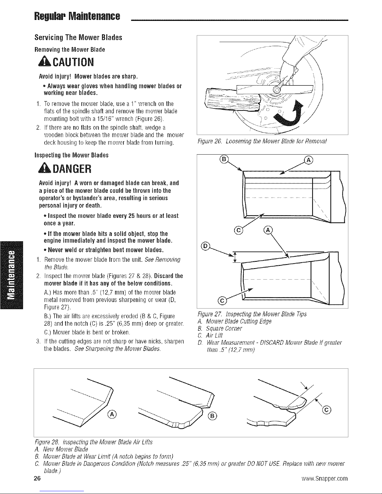
Servicing The Mower Blades
Removing theMower Blade
, ,CAUTION
Avoid injury! Mower blades are sharp.
* Always wear gloves when handling mower blades or
working near blades.
1. To removethe mower blade,use a 1" wrench on the
flats of the spindle shaft and remove the mower blade
mounting bolt with a 15/16" wrench (Figure 26).
2. If there are no flats on the spindle shaft, wedge a
wooden block betweenthe mower bladeand the mower
deck housing to keepthe mower bladefrom turning.
inspecting the Mower Blades
, ILDANGER
Avoid injury! Aworn or damaged blade can break, and
a piece of the mower blade couldbe thrown into the
operator's or bystander's area, resulting in serious
personal injury ordeath.
,, inspect the mower blade every 25 hours or at least
oncea year.
,,if the mower blade hitsa solid object, stop the
engine immediatelyand inspectthe mower blade.
,, Never weld or straighten bent mower blades.
1. Removethe mower bladefrom the unit. BeeRemoving
the Blade,
2. Inspect the mower blade (Figures 27 & 28). Discardthe
mower blade if it hasany ofthe below conditions.
A.) Has morethan .5" (12,7 mm) of the mower blade
metal removed from previous sharpening or wear (D,
Figure27).
B,)The air lifts are excessivelyeroded(B & C, Figure
28) andthe notch (C) is .25" (6,35 mm) deep or greater.
C.) Mower blade is bent or broken.
3. If the cutting edgesarenot sharp or have nicks, sharpen
the blades. See Sharpening the Mower Blades.
Figure26. Loosening the Mower Bladefor Removal
\
Figure27, Inspecting theMower BladeTips
A. Mower BladeCutting Edge
B, Square Corner
C. Air Lift
D. WearMeasurement- DISCARDMower Bladelf greater
than .5" (12,7 ram)
®
Figure28. inspecfing the Mower BladeAir Lifts
A. New Mower Blade
B, Mower Bladeat WearLimit (A notch begins to form)
C. Mower Bladein Dangerous Condition (Notch measures.25" (6,35 ram) or greater DO NOTUSE,Replacewith newmower
blade.)
26 www.Snapper.com

Sharpening the Mower Blade
, CAUTION
Avoid injury! Mower blades are sharp.
,, Alwayswear gloves when handling the mower
blades.
,, Alwayswear safety eye protectionwhen grinding.
RegularMaintenance
t
®
1. Sharpenthe mower blades with grinder, handfile. or
electric blade sharpener.
2. Sharpenthe mower blade by removing an equal amount
of material from each end of the mower blade.
3. Keepthe original bevel(A, Figure29) when grinding. DO
NOTchangethe mower blade bevel.
4. The mower bladeshould have a maximum 1/64" (0,40
ram) cutting edge (B) or less.
5. Balancethe mower bladesbefore installing.
Balancing the Mower Blades
, CAUTION
Avoidinjury! Keepmower blades balanced.
• An unbalanced mower blade can create excessive
vibrationand damage the unit or cause mower blade
failure.
1. Cleanthe mower bladeto remove any dried grass or
other debris.
2. SeeFigure30. Put the mower blade on a nail in a vise
and turn the mower bladeto the horizontal position.
3. Checkthe balanceof the mower blade. Ifeither end of
the mower blade moves downward, sharpen the heavy
end until the mower blade is balanced. SeeSharpening
the Mower Bladesfor proper sharpening instructions.
4. Repeatthe process until the mower blade remains in the
horizontal position.
Figure2! Sharpening BleMower Blade
A. Mower BladeBevel
B. Mower BladeCutting Edge
Figure30. Balancingthe Mower Blade
A. Nail
Reinstallingthe Mower Blades
1. Reinstalleachmower bladewith the air lifts pointing up
towards the mower deck asshown in Figure 31.
48" Models: Securewith the mower blade mounting
bolt and flat washer (A& B,Figure31) andtorque to 70
ft. Ibs (94 Nm).
2. If there are no flats on the spindle shaft, wedge a
wooden block betweenthe mower bladeand the mower
deck housing to keepthe mower bladefrom turning.
Figure31, Tighteningthe Mower Bladefor Installation
A. Mower Blade Mounting Bolt
B, Flat Washer
C. Mower BladeAir Lift (Points Up For Installation)
D. 4X4 WoodenBlock
27

RegularMaintenance
GroundSpeed Control Lever Adjustment
Thecontrol leverscan be adjusted inthree ways, The
alignment of the control levers,the placement of the levers
(how close the ends areto one another) and the height of
the levers can be adjusted.
ToAdjust the Handle Alignment
Loosenthe mount bolts (A, Figure32) and pivot the lever(s)
(B) to align with eachother.
ToAdjust the Handle Placement
Loosenthe jam nuts and adjust the placementbolt (C,
Figure33) in or out to properly adjust the leverend spacing.
ToAdjust the Handle Height
Removethe mounting hardwareandreposition the handle
either up or down from its original position. You will need
to readjust the handle alignment as described above.
Speed Balancing Adjustment
Ifthe rider veers to the right or leftwhenthe ground speed
control leversare in the maximum forward position, the top
speedof each of these levers can be balancedby turning the
adjustment bolt(s) (A, Figure33). Only adjust the speedof
the wheel that is traveling faster.
ToReduce the Speed of the FasterWheel
1. Loosenthe securing nut.
2. Turn thetop speed adjustment bolt COUNTER-
CLOCKWISEto reduce the speed.
3. Retightenthe securing nut when adjustment is
complete.
, WARNING
DONOTadjust the tractorfor a faster overallspeed
forward or reverse thanit was designed for.
Figure32. Contml LeverAdjustment
A. PlacementHardware
B. Ground 5 JeedControl Lever
Figure33. Top SpeedAdjustment
A. TopSpeedAdjusfinent Bolt
B. Contml Lever Base
C. Alignment Hardware
Neutral Adjustment
If the tractor "creeps" while the ground speedcontrol levers
are locked in their NEUTRALpositions, seeyour dealer.
28 www.Snapper.com

ParkingBrakeAdjustment
1. Disengagethe PTO,stop tile engine,engagetile parking
brake,and removethe key from the ignition.
2. Raisethe seat plateto gainaccessto the parking brake
components.
3. Measurethe distancefrom the top of the brakespring
rod (C, Figure 34) to the top of the lock nut (D) on both
sides of the unit. The measurementshould be .50"
(1,27 cm). If not, adjust the Iocknut to achievethe
measurementof .50" (t ,27 cm)
4. Measurethe distance betweenthe bottom of the brake
shaft weldment (G) and the top of the set collar (F). The
measurementshould be .375" (0,95 cm). If not,
position the set collar until the measurementequals
.375" (0,95 cm).
if this does notcorrectthe brakingproblem,seeyour
Snapper Prodealer.
RegularMaintenance
Figure34, Parking BrakeAdjustment
A. Brake Spring
B, First Measurement- .50" (1,27 cm)
C. Brake Spring Rod
D. LockNut
E, SecondMeasurement - .375" (0,95 cm)
F. Set Collar
G, Brake Shaft Weldment
29

RegWr Maintenance
Return-to-NeutraJAdjustment
Todetermine if it is necessaryto adjust the neutral return,
perform the following steps.
1. Disengagethe PTO,engagethe parking brakeandturn
off the engine.
2. Move the ground speed control levers into the operating
position, pull the levers rearward and release.
3. Move the ground speed control levers out towards the
neutral position. If the leversdo not align with the
notches in the neutral lock plate, it is necessaryto
adjust the neutralreturn rod (B, Figure35).
Adjustment
,II WARNING
Toavoid seriousinjury, perform adjustments only with
the enginestopped, the key removed andthe tractoron
level ground.
1. Disengagethe PTO,engagethe parking brakeandturn
off the engine.
2. Therearethree jam nuts (A, Figure 35) on the linkage
rod (B). The first two are usedtogetherto turn the rod
and the third (towards the front of the machine) is used
to lock the rod in place. Loosenthe jam nutthat locks
against the ball joint and turn the linkage rod to adjust.
If the machine creepsforward, turn the linkagerod
CLOCKWISE(while standing atthe rear of the machine,
facing forward). If the machine creeps backward,turn
the rod COUNTER-CLOCKWISE.
3. Lock the jam nut (A) againstthe ball joint when neutral
is achieved.
4. Pull the ground speed control lever rearwardand release
to check position again. Adjust as necessaryto align
the ground speedcontrol levers with the notches in the
neutral lock plate.
NOTE.+ This adjustment should not be performed while the
machine is running,
©
Figure35. Retum-to-Neutral Adjustment
A. Jam Nuts
B. Neutral Return Rod
30 www.Snapper.com

Deck Rod Timing Adjustment
1. Parkthe machine on aflat, levelsurface, Disengagethe
PTO,engagethe parking brake,turn off the engine,and
removethe ignitionkey. Reartires must be inflatedto
15 psi (1,03 bar);front tires to 40 psi (2,76 bar).
2. Tocheck the lift rod timing, measureandrecord the
distance betweenthe liftpivots and the rod pivots.
Repeatfor other side of unit, SeeFigure36.
3. If the measurementsfor the rods are equal, no further
adjustment is required, If the measurementsare NOT
equal (greaterthan 1/8" (3,17 ram) difference),
adjustment is required continue with Step4.
4. Lock the deck lift pedal in the 4-1/2" (11,47 cm)
position. Removethe cutting height adjustment pin and
lower the mower deck.
5. Toensurethat the deck is in the lowest position, push
the pedal by handtowards the rear of the unit and install
the height adjustment pin in the 3" (7,6 cm) position to
hold in place.
6. Block up the mower deck until all hanger chains are
slack. Referto Figure38.
7. SeeFigure37. To adjust the lift rod, loosen thejam nut
on the front clevis then removethe 1/2" clevis pin
fastening the clevis to the lift pivot arm. Turnthe clevis
clockwise to shorten the distance betweenthe rod pivots
or counterclockwiseto lengthenthe distance between
the rod pivots. Reinstallthe clevis on the lift pivot arm
and securewith the 1/2" clevis pin previously removed.
Tighten the jam nut against the clevis.
8. Removethe blocks from the underthe mower deck.
9. Removethe cutting height adjustment pin from in front
of the deck lift pedal arm. Lift mower deckand reinstall
adjustment pin in desired mowing height.
RegularMaintenance
I
Figure36. CheckLift Rod Timing
Adjust
Here
Figure37. Adjust Lift Rod Timing
Deck LevelingAdjustment
NOTE:Beforeadjusting the deck leveL the deck lift rod
timing must be checked and/or adjusted,
1. Parkthe machine on aflat. levelsurface. Disengagethe
PTO,stop the engine and engagethe parking brake.
Reartires must be inflated to 15 psi (1,03 bar); front
tires to 40 psi (2,76 bar).
2. Lock the deck lift pedal in the 4-1/2" (11,47 cm)
position. Placethe deck height adjustment pin in the 4"
position and lower the deck lift pedaluntil the arm
contacts the pin.
3. Place2 x 4 blocks under eachcorner of the mower deck
with the 3-1/2" sides being vertical. Placea 1/4" (0,64
cm)thick spacer ontop of the rear 2 x 4 blocks. See
Figure38.
4. Adjust the front eyebolts until the chains aretight and
the deck is still resting onthe 2 x 4's. Tighten the jam
nuts. SeeFigure39.
5. Loosenthe nuts and allow the rear of the deck to rest on
the 2 x 4's and 1/4" spacers. Slidethe chains down in
the slots until the chains are tight and tighten the nuts.
SeeFigure39.
6. Removeall 2 x 4 blocks and spacers from under the
mower deck.
Figure38. 2 x4 Locations
Figure39. Hanger ChainAdjustment
31
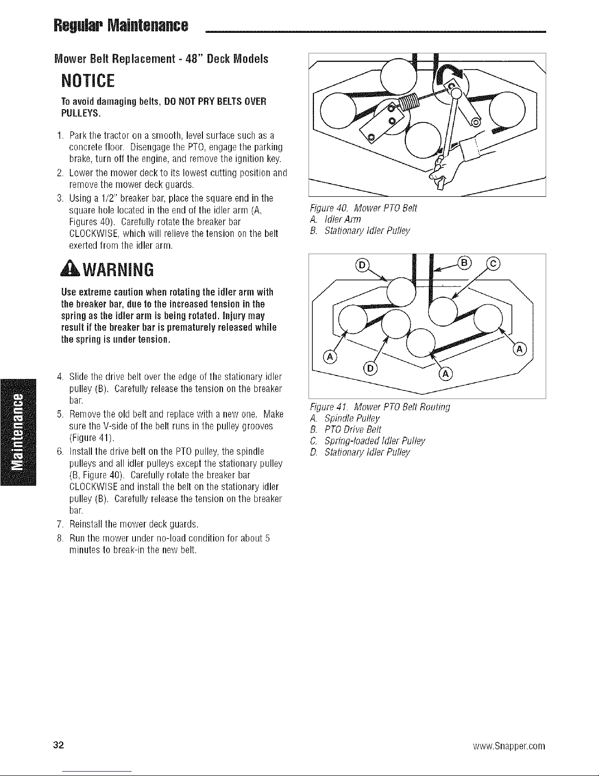
RegWr MaJflteflaflce
Mower Belt Replacement - 48" DeckModels
NOTICE
Toavoid damaging belts, DONOTPRY BELTSOVER
PULLEYS.
1. Parkthe tractor on a smooth, levelsurface such as a
concrete floor. Disengagethe PTO,engagethe parking
brake,turn off the engine, and removethe ignition key.
2. Lowerthe mower deck to its lowest cutting position and
removethe mower deck guards.
3. Using a 1/2" breakerbar,placethe square end in the
square hole located in the end of the idler arm (A,
Figures40). Carefullyrotatethe breaker bar
CLOCKWISE,which will relievethe tension onthe belt
exerted from the idler arm.
, WARNING
Figure40. Mower PTOBelt
A. Idler Arm
B. Stationary Idler Pulley
Use extremecautionwhen rotating the idler arm with
the breaker bar, due tothe increasedtensioninthe
spring as the idler arm is being rotated, injurymay
result if the breaker bar is prematurelyreleased while
the spring isunder tension.
4. Slidethe drive belt over the edge of the stationary idler
pulley (B). Carefully releasethe tension on the breaker
bar.
5. Removethe old belt and replacewith a new one. Make
sure the V-side of the belt runs in the pulley grooves
(Figure41).
6. Install the drive belt on the PTOpulley,the spindle
pulleys and all idler pulleys exceptthe stationary pulley
(B, Figure40). Carefully rotatethe breakerbar
CLOCKWISEand install the belt on the stationary idler
pulley (B). Carefully releasethe tension on the breaker
bar.
7. Reinstallthe mower deck guards.
8. Runthe mower under no-load condition for about 5
minutes to break-in the new belt.
f
Figure41. Mower PTOBelt Routing
A. Spindle Pulley
B, PTODriveBelt
C. Spring-loaded Idler Pulley
D. Stationary Idler Pulley
32 www.Snapper.com
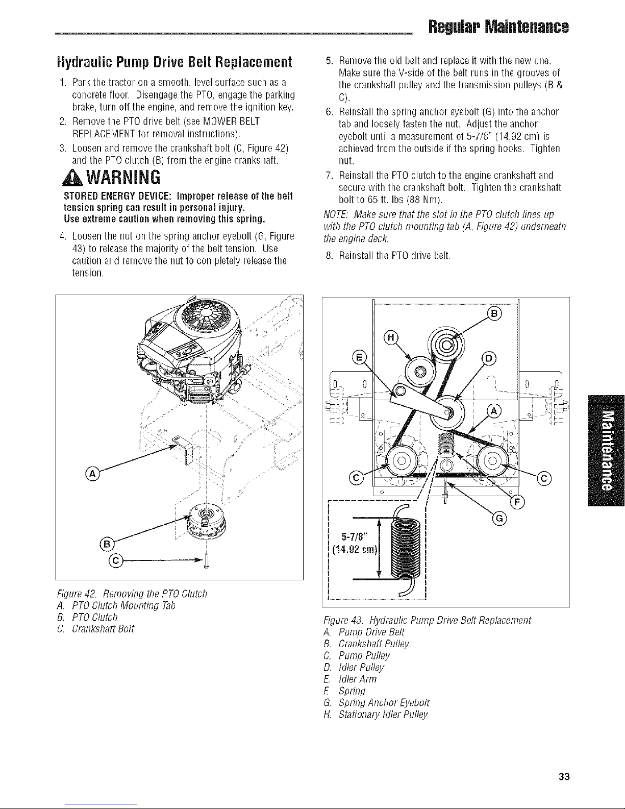
RegularMaintenance
HydraulicPumpDrive BeRtReplacemeflt
1. Parkthe tractoron a smooth, levelsurface such as a
concrete floor. Disengagetbe PTO,engagetbe parking
brake,turn off the engine,andremovetheignitionkey.
2. Removethe PTOdrive belt (seeMOWERBELT
REPLACEMENTfor removal instructions).
3. Loosenand removethe crankshaftbolt (C, Figure42)
and the PTOclutch (B) from the engine crankshaft.
t ,WARNING
STOREDENERGYDEVICE:improper release ofthe belt
tensionspringcanresultin personalinjury.
Useextreme cautionwhen removingthisspring.
4. Loosenthe nut on the spring ancbor eyebolt (G, Figure
43) to releasethe majority of the belt tension. Use
caution and removethe nut to completely releasethe
tension.
5. Removethe old belt and replaceit with the new one.
Makesure the V-side of the belt runs in the grooves of
the crankshaftpulley and the transmission pulleys (B &
C).
6. Reinstallthe spring anchor eyebolt (G) into the anchor
tab and loosely fastenthe nut. Adjust the anchor
eyebolt until a measurement of 5-7/8" (14,92 cm) is
achieved from the outside if the spring hooks. Tighten
nut.
7. Reinstallthe PTOclutch to the enginecrankshaft and
secure with the crankshaft bolt. Tightenthe crankshaft
bolt to 65 ft. Ibs(88 Nm).
NOTE.Makesure that the slot in the PTOclutch lines up
with the PTOclutch mounting tab (A, Figure42) underneath
theenginedeck,
8. Reinstallthe PTOdrive belt.
• _5_
11 I i _
Figure42. Removing the PTOClutch
A. PTOClutch Mounting Tab
B, PTOClutch
C. CrankshaftBolt
I
I
¸%¸¸¸{
/
/
5-7/8"
(14.92 cm)
Figure43. Hydraufic Pump Drive Belt Replacement
A. Pump DriveBelt
B, CrankshaftPulley
C. Pump Pulley
D. Idler Pulley
£ IdlerArm
E Spring
G, Spring Anchor Eyebolt
14_Stationary Idler Pulley
33

RegWr MaJflteflaflce
Battery Maintenance
NOTE, This unit is equipped with a maintenance-freeBCIU1
battery,
Cleaningthe Batteryand Cables
WARNING
BecarefuJwhen handlingthe battery. Avoidspilling
electrolyte. KeepBarnes and sparksawayfram the
battery.
Whenremovingor installingbatterycables,disconnect
the negativecabJeFIRSTand reconnectitLAST.if not
doneinthis order,thepositive terminalcanbe shortedto
the frame byatool.
1. Disconnectthe cables from the battery,negative(black)
cablefirst (B, Figure44).
2. Cleanthe battery terminals andcable ends with a wire
brush until shiny.
3. Reinstallthe battery and reattachthe battery cables,
positive (red) cablefirst (A).
4. Coatthe cableends and battery terminals with
petroleum jelly or non-conducting grease.
Figure44. Battery Compartment
A. Positive (÷) Cable& Terminal
B. Negative(-) Cable& Terminal
34 www.Snapper.com
RegularMaintenance
BatteryService
CheckingBattery Voltage
WARNING
Keepopen flames and sparksaway from the battery;
the gasses comingfrom it are highlyexplosive.
Ventilatethe batterywell duringcharging.
A voltmeter can be used to determine condition of battery.
When engine is off, the voltmeter shows battery voltage,
which should be 12 volts. When engine is running, the
voltmeter shows voltage of charging circuit which normally
is 13 to 14 volts.
A dead battery or one too weakto start the engine maynot
meanthe battery needsto be replaced.Forexample, it may
meanthat the alternator is not charging the battery properly.
If there is any doubt about the cause of the problem, see
your dealer. If you needto replacethe battery,follow the
steps under Cleaningthe Battery & Cablesin the Regular
MaintenanceSection.
Charginga CompletelyDischarged Battery
1. Beawareof all the safety precautionsyou should
observe during the charging operation. If you are
unfamiliar with the use of a battery charger and
hydrometer, havethe battery serviced byyour dealer.
2. Add distilled water sufficient to cover the plate(fill to the
proper levelnear the end of the charge).If the battery is
extremely cold, allow it to warm before adding water
becausethe water levelwill rise as it warms. Also, an
extremely cold battery will not accept a normal charge
until it becomeswarm.
3. Always unplug or turn the charger off before attaching
or removing the clamp connections.
4. Carefullyattachthe clamps to the battery in proper
polarity (usually redto [÷] positive and blackto [-]
negative).
5. While charging, periodically measurethe temperature of
the electrolyte. If the temperature exceeds125° F(51.6°
C), or if violent gassing or spewing of electrolyte occurs,
the charging rate must be reducedor temporarily halted
to prevent batterydamage.
6. Chargethe battery until fully charged (until the specific
gravity of the electrolyte is t .250 or higher and the
electrolyte temperature is at least 60° F).The best
method of making certain abattery is fully charged, but
not over charged, is to measurethe specific gravity of a
cell once per hour. The battery is fully chargedwhen the
cells are gassing freely at low charging rate and less
than 0.003 change in specific gravity occurs over a three
hour period.
JumpStarting With Auxiliary (Booster) Battery
Jump starting is not recommended. However,if it must be
done,follow these directions. Both booster and dis-charged
batteries should be treated carefully when using jumper
cables. Followthe steps below EXACTLY,being careful not to
cause sparks. Referto Figure 45.
1. Both batteries must be of the samevoltage.
2. Position the vehicle with the booster battery adjacentto
the vehicle with the discharged battery so that booster
cables can be connectedeasilyto the batteries in both
vehicles. Makecertainvehicles do not touch each other.
3. Wearsafety glassesandshield eyes andface from
batteriesat all times. Besure vent caps aretight. Place
damp cloth overvent caps on both batteries.
4. Connectpositive (÷) cableto positive postof discharged
battery (wired to starter or solenoid).
5. Connectthe other end of same cable to same post
marked positive (÷) on booster battery.
6. Connectthe second cable negative(-) to other post of
booster battery.
7. Makefinal connection on engine block of stalled vehicle
away from battery. Do not leanover batteries.
8. Start the engine of the vehicle with the booster battery.
Wait a few minutes, then attempt to start the engine of
the vehicle with the discharged battery.
9. If the vehicle does not start after cranking for thirty
seconds, STOPPROCEDURE.Morethan thirty seconds
seldom starts the engine unless some mechanical
adjustment is made.
10. After starting, allow the engine to return to idle speed.
Removethe cable connection atthe engine or frame.
Then removethe other end ofthe same cable from the
booster battery.
11. Removethe other cableby disconnecting atthe
discharged batteryfirst and then disconnect the
opposite end from the booster battery.
12. Discardthe damp cloths that were placed over the
batteryvent caps.
35

RegularMaintenance
THIS HOOK-UP FOR NEGATIVE GROUND VEHICLES
To
Starter_
Switch
Starting _
Vehicle
Battery
To Ground
Figure45, Jump Starting
-%
I
To
Switch
Jumper Cable
_ tarter
Discharged
Vehicle
Battery
J
__ Engine
Block
MAKE CERTAIN VEHICLES DO NOT TOUCH
AWARNING
Any procedureotherthan the precedingcouldresult in:
(1) personal injurycausedby electrolyte squirting
out the batteryvents,
(2) personal injuryor property damage due to
battery explosion,
(3) damage to the chargingsystem of the booster
vehicleor of the immobilized vehicle.
Donot attempt to jump start a vehicle havinga frozen
battery because the battery may rupture orexplode, if
a frozen battery is suspected, examine all fill ventson
the battery, if ice canbeseen orif the electrolyte fluid
cannotbeseen, donat attempt to start with jumper
cablesas long as the battery remains frozen.
WARNING
Foryourpersonal safety, use extreme carewhen jump
starting. Never expose battery to open flameor electric
spark - battery action generates hydrogengas which is
flammable and explosive. Do nat allow battery acid to
contactskin, eyes,fabrics, or painted surfaces.
Batteriescontaina sulfuric acid solution which can
causeserious personalinjury or property damage.
When removing or installingbattery cables, disconnect
the negative cable FIRSTandreconnect it LAST.if not
donein this order,the positiveterminal canbeshorted
to the frame by a tool.
Toavoid enginedamage, donat disconnect battery
while engineis running. Be sureterminal connections
are tight before starting.
36 www.Snapper.com

RegWr MaJflteflaflce
Storage
TemporaryStorage (38 DaysOr Less)
Remember,the fuel tank will still contain some gasoline, so
neverstore the unit indoors or in anyother area where fuel
vapor could travel to any ignition source. Fuelvapor is also
toxic if inhaled,so neverstore the unit in anystructure used
for human or animal habitation.
Here is a checklist of things to do when storing your unit
temporarily or in betweenuses:
,, Keepthe unit in an area away from where children may
come into contact with it. If there's any chanceof
unauthorized use, removethe spark plug (s) and put in a
safe place.Besurethe spark plug opening is protected
from foreign objects with asuitable cover.
,, If the unit can't be stored on a reasonablelevelsurface.
chockthe wheels.
,, Cleanall grass anddirt from the mower.
LongTermStorage (Longer Than30 Days)
Beforeyou store your unit for the off-season, read the
MaintenanceandStorage instructions in the SafetyRules
section, then perform the following steps:
1. Draincrankcaseoil while engine is hot and refill with a
grade of oil that will be required when unit is usedagain.
2. Preparethe mower deckfor storage asfollows:
a. Removemowerdeckfromthe unit.
b. Cleanundersideof mowerdeck.
c. Coatall baremetalsurfaceswith paintor lightcoatof
oil to preventrusting.
3. Cleanexternal surfaces and engine.
4. Prepareenginefor storage. Seeengine owner's
manual.
5. Cleanany dirt or grass from cylinder headcooling fins.
engine housing and air cleanerelement.
6. Coverair cleanerand exhaustoutlet tightly with plastic
or other waterproof material to keepout moisture, dirt
and insects.
7. Completelygreaseand oil unit as outlined in the Normal
Caresection.
8. Cleanup unit andapply paint or rust preventativeto any
areaswhere paint is chipped or damaged.
9. Besure the battery is filled to the proper levelwith water
and is fully charged. Battery lifewill be increased if it is
removed,put in a cool, dry placeand fully charged
about onceamonth. If battery is left in unit, disconnect
the negativecable.
AWARNING
Neverstore the unit, with gasoline in engineorfuel
tank, in a heated shelter or in enclosed, poorly
ventilatedenclosures. Gasolinefumes mayreach an
openflame, sparkor pilot light (such as a furnace,
water heater, clothesdryer, etc.) and causean
explosion.
Handlegasoline carefully. Dis highly flammable and
carelessuse couldresult in seriousfire damage to
yourperson or property.
Drain fuel intoan approved containeroutdoorsaway
fram open flame or sparks.
10. Drainfuel system completely or adda gasoline stabilizer
to the fuel system. If you havechosen to use afuel
stabilizer and havenot drained the fuel system, follow all
safety instructions and storage precautionsin this
manualto prevent the possibility of fire from the ignition
of gasoline fumes. Remember,gasoline fumes cantravel
to distant sources of ignition and ignite, causingrisk of
explosion and fire.
NOTE.Gasoline,if permitted to stand unused for extended
periods (30 days or more), may developgummy deposits
which canadverselyaffect theengine carburetor and cause
enginemalfunction. Toavoid this condition, add a gasoline
stabilizer to the fuel tank and run the enginea fewminutes,
or drain all fuel from the unit beforeplacing it in storage.
Starting After Long Term Storage
Beforestartingtheunitafterit hasbeenstoredfor along
periodoftime,performthefollowingsteps.
1. Removeany blocks from under the unit.
2. Install the battery if it was removed.
3. Unplugthe exhaust outlet and air cleaner.
4. Fillthe fuel tank with fresh gasoline. Seeengine
manualfor recommendations.
5. Seeengine owner's manualandfollow all instructions
for preparing engine after storage.
6. Checkcrankcase oil levelandadd proper oil if
necessary.If any condensation has developedduring
storage, drain crankcaseoil and refill.
7. Inflatetires to proper pressure. Checkfluid levels.
8. Start the engine and let it run slowly. DONOTrun at
high speedimmediately after starting. Besure to run
engine only outdoors or in well ventilated area.
37

TroubleshooUflg
Troubleshooting
TroubleshootingChart
While norrnal care and regular maintenancewill extend the
life of your equipment, prolonged or constant use may
eventually require that service be performed to allow it to
continue operating properly.
Thetroubleshooting guide below lists the most common
problems, their causes and remedies.
Seethe information on the following pagesfor instructions
_WARNING
Toavoid seriousinjury, perform maintenance an the
tractorormower onlywhenthe engine is stoppedand
the parking brake engaged.
Always remove the ignition key, disconnect the spark
plug wire and fasten it away from the plug before
beginning the maintenance, to preventaccidental
startingof the engine.
on how to perform most of these minor adjustments and
service repairs yourself. If you prefer, all of these
procedures can be performed for you byyour local
authorized dealer.
Troubleshooting the Rider
Problem
Engine will not turnoveror start.
Engine startshard or rune poorly. 1. Fuel mixture too rich. 1. Cleanair filter. Check choke adjustment.
Engine knocks. 1. Low oil level. 1. Check/add oil as required.
Excessive oil coesulnption. 1. Engine running too hot. 1. Cleanenginefins, blower screen and
Engine exhaest is black. 1. Dirty air filter. 1. Replaceair filter. Seeenginemanual.
Cause
1. Parking brake not engaged.
2. PTO(electric clutch) switch
in ON position.
3. Ground speed control levers
not in "NEUTRAL" position.
4. Out of fuel.
5. Engineflooded.
6. Fuseblown.
7. Batteryterminals require
cleaning.
8. Battery discharged or dead.
9. Wiring looseor broken.
10. Solenoid or starter motor faulty.
11. Safety interlock switch
faulty.
12. Spark plug(s) faulty, fouled
or incorrectly gapped.
13. Water in fuel.
14. Gas is old or stale.
2. Spark plug faulty, fouled, or 2. Cleanand gap or replace.
incorrectly gapped. (Seeengine manual.)
2. Using wrong grade oil. 2. See engine manual.
2. Using wrong weight oil. 2. See engine manual.
3. Toomuch oil in crankcase. 3. Drain excessoil.
2. Engine choke control 2. Open choke control.
is in closed position.
Remedy
1. Engage parking brake.
2. Placein OFFposition.
3. Move ground speedcontrol levers to
"NEUTRAL" position.
4. If engineis hot, allow it to cool, then refill
the fuel tank.
5. Move choke control to closed position.
6. Replacefuse.
7. Cleanthe battery terminals
8. Rechargeor replace.
9. Visually check wiring & replace broken or
frayed wires. Tightenloose connections.
10. Repair or replace. Seeauthorized dealer
11. Replaceas needed.Seeauthorized
servicedealer.
12. Cleanandgap or replace.
Seeengine manual.
13. Drain fuel & replace with fresh fuel.
14. Drain fuel & replace with fresh fuel.
air cleaner.
38 www.Snapper.com

Troubleshooting
Rider Trouh/eshooting Continued,
Problem Cause Remedy
Engine railS, bnt rider will 1. Transmission releaselever(s) 1. Move the transmission releaselever(s) to
net drive, in "open" position, the "closed" position.
2. Belt is broken. 2. See Drive Belt Replacement.
3. Drive belt slips. 3. See problem and cause below.
4. Brake is not fully released. 4. Seeauthorized service dealer
Rider drive belt slips. 1. Pulleys or belt greasy or oily. 1. Clean as required.
2. Tensiontoo loose. 2. Adjust spring tension.
See Drive Belt Replacement
3. Belt stretched or worn. 3. Replacebelt.
Brake wiii not bold. 1. Brake is incorrectly adjusted. 1. See BrakeAdjustment.
2. Brake padsworn. 2. Replacewith new brake pads.
Ridersteersor bandies poorly. 1. Steering linkage is loose. 1. Check andtighten any loose connections.
2. Improper tire inflation. 2. See Regular MaintenanceSection.
Troubleshooting the Mower
Problem Cause Remedy
Mower will not raise. 1. Lift linkage not properly attached 1. Seeauthorized service dealerfor repair.
or damaged.
Engine stalls easily witb 1. Engine speedtoo slow. 1. Set to full throttle.
mowerengaged. 2. Ground speedtoo fast. 2. DecreaseGround Speed.
3. Cutting height settoo low. 3. Cut tall grass at maximum cutting
height during first pass.
4. Discharge chutejamming 4. Cut grasswith discharge pointing toward
with cut grass, previously cut area.
Excessive mower vibration. 1. Blade mounting bolts are loose. 1. Tighten to 70 ft.lbs. (94 N.m.).
2. Mower blades,arbors, 2. Checkand replaceas necessary.
or pulleys are bent.
3. Mower blades are out 3. Remove,sharpen, and balanceblades.
of balance. SeeMaintenance Section.
4. Belt installed incorrectly. 4. ReinstallCorrectly.
Excessive belt wear or breakage. 1. Bentor rough pulleys. 1. Repair or replace.
2. Using incorrect belt. 2. Replacewith correct belt.
Mower drive belt slips 1. Idler pulley spring broken or not 1. Repair or replaceas needed.
orfails todrive, properly attached.
2. Mower drive belt broken. 2. Replacedrive belt.
Mower does not engage. 1. Electrical wiring damage. 1. Locate& repair damagedwire.
2. PTOclutch not adjusted 2. See PTOClutch Adjustment section
3. Batteryvoltage too low. 3. Rechargebattery and check alternator.
See BatteryMaintenancesection.
39

Troubleshootiflg
TroubleshootingCommonCutting Problems
Problem Cause
Streaking.
Scalphlg.
Stepped c[Inhlg. 1. Deck is not leveledcorrectly. 1. Levelthe deck correctly.
1. Blades are not sharp.
2. Bladesareworn down to far.
3. Engine speedis too slow.
4. Ground speed istoo fast.
5. Deck is plugged with grass
6. Not overlapping cutting rows
enough.
7. Not overlapping enoughwhen
turning.
1. Lawn is uneven or bumpy.
2. Mower deck cutting height is
set too low.
3. Ground speed istoo fast.
4. Deck is not leveled correctly.
5. Tire pressure is low or uneven
2. Tires are not properly inflated. 2. Checkand inflate the tires.
3. Bladesare damaged. 3. Replacethe blades.
4. Deck shell is damaged. 4. Repairor replacethe deck.
5. Mower spindle is bentor loose. 5. Repairor replacethe spindle.
6. Bladesare installed incorrectly. 6. Reinstallthe bladescorrectly.
Remedy
1. Sharpen your blades.
2. Replaceyour blades.
3. Always mow at full throttle.
4. Slow down.
5. Cleanout the mower.
6. Overlapyour cutting rows.
7. When turning your effective cutting width
decreases-overlap more when turning.
1. Roll or level the lawn.
2. Raisethe cutting height.
3. Slow down.
4. Correctly levelthe deck.
5. Check and inflate the tires.
Uilevee CLiniilg.
Stiegers.
1. Deck is not leveled correctly. 1. Levelthe deck correctly.
2. Bladesare dull or worn. 2. Sharpen or replacethe blades.
3. Bladesare damaged. 3. Replacethe blades.
4. Deck is clogged with grass 4. Cleanout the deck.
clippings.
5. Deck shell is damaged. 5. Repairor replacethe deck.
6. Mower spindle is bentor loose. 6. Repairor replacethe spindle.
7. Bladesare installed incorrectly. 7. Reinstallthe bladescorrectly.
8. Tires are not properly inflated. 8. Checkand inflate the tires.
1. Blades are not sharp or nicked. 1. Sharpen your blades.
2. Bladesareworn down too far. 2. Replaceyour blades.
3. Engine speedis too slow. 3. Always mow at full throttle.
4. Ground speed istoo fast. 4. Slow down.
5. Deck is plugged with grass. 5. Cleanout the mower.
40 www.Snapper.com

Specifications
$pecJ|JcatJofls
NOTE,Specifications are correct at time of printing and are subject to change without notice.
ENGINE:
TRANSMISSIONS:
HydroGearZL-KMEF-3LTC-1LLX(LH)
26 HP Briggs & Stratton
Make Briggs & SrrattoN Type
Medel 44P777-O124-G1
Horsepower 26 @ 3600 rpm Speeds
Displacement 44.2 Cu. hi (724 cc) @ 3400 rpm
Electrical System 12 Voq Starter, 16 amp. Aqernutor, Continuous Torque
Oil Capacity 2.0 US qt.. (1.9 L) w/Fiqer Maximnm Weight
Battery: 340 CCA Output
HydroGearZL-GMEF-3LTB-1LLX(BH)
ZT2800
Hydraulic Finial
on Axle
SAE20W-50motoroil
Forward:0-7MPH(0-11,27km/h)
Reverse:0-5MPH(0-8.05km/h)
180ft. Ibs.(244N.m.)
440Ibs. (200Kg)peraxle
CHASSIS: DIMENSIONS:
Fuel Tank Capacity: 8 Gallons (30,3 L)
RearWheels TireSize:20x8.00-10(48"Model) OverallLength:
inflationPressure:15psi(1,03bur) OverallWidth
FrontWheels TireSize:11x 4.00- 5 48"Model:
inflationPressure:40psi(2,76bur) Height:
Weight (apx.}:
EnginePower Bating information
Thegross power rating for individual gas engine models is labeledin accordance with SAE(Society of Automotive Engineers)
code J1940 (Small Engine Power & TorqueRating Procedure), and rating performance has beenobtained and corrected in
accordancewith SAEJ1995 (Revision 2002-05). Torquevaluesare derived at 3060 RPM; horsepower valuesare derived at
3600 RPM.Actual gross engine power will be lower and is affected by, among other things, ambient operating conditions and
engine-to-enginevariability. Given both the wide array of products on which engines are placed andthe variety of
environmental issues applicableto operating the equipment, the gasenginewill not developthe rated gross power when used
in a given pieceof power equipment (actual "on-site"or net horsepower). This difference is due to a variety of factors
including, but not limited to, accessories(air cleaner,exhaust, charging, cooling, carburetor, fuel pump, etc.), application
limitations, ambient operating conditions (temperature, humidity, altitude), and engine-to-enginevariability. Dueto
manufacturing and capacity limitations. Briggs& Stratton may substitute an engine of higher rated powerfor this Series
engine.
68" (173cm)
49" (125cm)
43" (109cm)
750Ibs. (340kg)
41
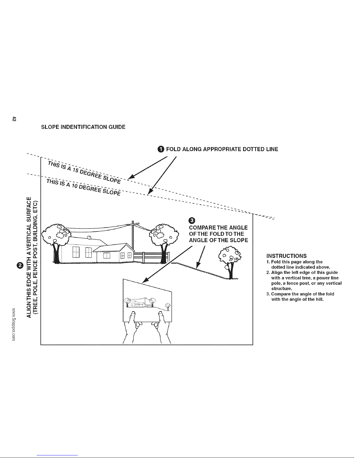
PO
SLOPE INDENTIFICATION GUIDE
O
CJ)
o
LLI
Q:
_q
L)
LLI
za=
wig
{5"
_0
Zw
FOLD ALONG APPROPRIATE DOTTED LiNE
O
COMPARE THE ANGLE
OFTHE FOLD TO THE
ANGLE OFTHE SLOPE
iNSTRUCTiONS
1. Fold this page along the
dotted line indicated above.
2. Align the left edge of this guide
with a vertical tree, a power line
pole, a fence post, or any vertical
structure.
3. Compare the angle of the fold
with the angle of the hill.

Notes

Notes

ZERO-TURNR/O/NGMOWER
ProductSpecifications:
ENGINE:
26 HP Brig[Is& Stratton
Make Briggs& StrattoN
Model 44P777-O124-G1
OilCapacity 2.0USqt.(1,9L)w/Filter
CHASSIS:
FuelTank
RearWheels
FrontWheels
Capacity:8 Gallons(30,3L)
TireSize:20x 8.00-10 (48"Model)
InflationPressure:15psi(1,03bar)
TireSize:11x 4.00- 5
InflationPressure:40psi(2,76bar)
CommonService Parts:
BELTSAND BLADES:
TRACTOR
pumpDriveBelt 5022178
48" MOWERDECK
DeckDriveBelt 5101301
MowerBlade 5020843
SNAPPWR®
535 Macon St.
McDonough, GA 30253
www.snapper.com
 Loading...