

Page 1
Attachment
Illustrated
Parts List
Attachment
Mfg. No. Description
1694387 60" Dozer Blade & Hitch
MANUFACTUR ING, INC.
500 N. Spring Street / PO Box 997
Port Washington, WI 53074-0997 USA
www.simplicitymfg.com
© Copyright Simplicity Manufacturing, Inc. All Rights Reserved. Printed In USA.2003
11/2003
Rev.
TP 400-3875-00-AT-SMA
Page 2
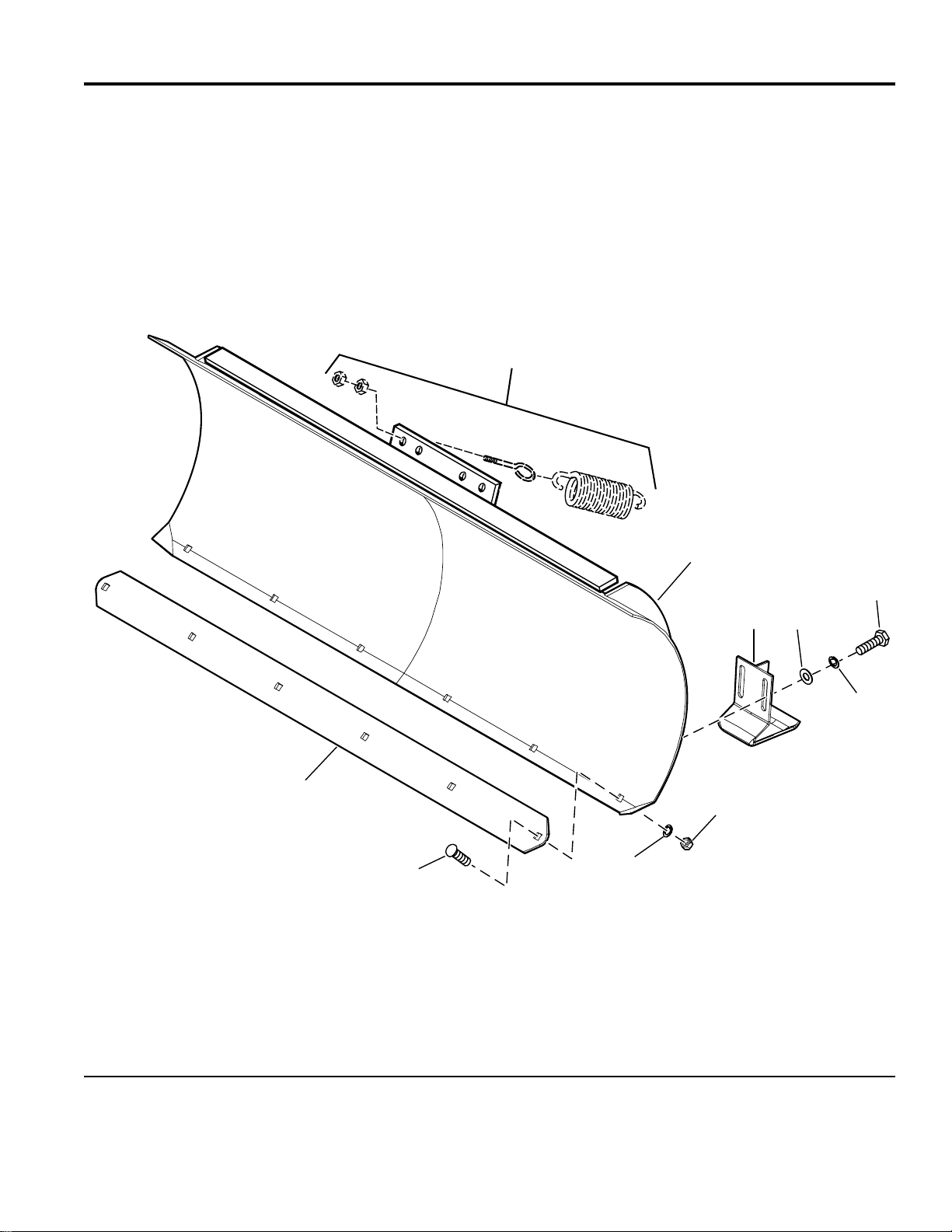
60" Dozer Blade Group
NOTE: Unless noted otherwise,
use the standard hardware torque
specification chart.
986340
See Hitch Group
1
5
2
3
4
8
7
4
6
The above parts group applies to the following Mfg. Nos.:
1694387 - 60" Dozer Bla
© Copyright Simplicity Manufacturing, Inc. All Rights Reserved.
2003
1
TP 400-3875-00-AT-SMA
Page 3

60" Dozer Blade Group
PART NO. DESCRIPTIONREF NO. QTY.
1 1725268 1 BLADE ASSEMBLY
2 1725353 2 SHOE ASSEMBLY
3 1922755 4 WASHER, 3/8
4 1916965 13 LOCKWASHER, 3/8
5 1921965 4 CAPSCREW, Hex Head, 3/8-16 x 3/4
6 1916950 9 NUT, Hex, 3/8-16
7 1931350 9 CARRIAGE BOLT, 3/8-16 x 1
8 1725356 1 P L A T E , Wear
Footnotes
The above parts group applies to the following Mfg. Nos.:
1694387 - 60" Dozer Bla
© Copyright Simplicity Manufacturing, Inc. All Rights Reserved.
2003
2
TP 400-3875-00-AT-SMA
Page 4

Hitch Group
NOTE: Unless noted otherwise,
use the standard hardware torque
specification chart.
2
986341
7
8
6
9
5
10
11
12
To frame
4
3
14
13
1
15
16
17
27
26
19
18
25
20
624
22
21
23
The above parts group applies to the following Mfg. Nos.:
1694387 - 60" Dozer Bla
© Copyright Simplicity Manufacturing, Inc. All Rights Reserved.
2003
3
TP 400-3875-00-AT-SMA
Page 5

Hitch Group
PART NO. DESCRIPTIONREF NO. QTY.
1 172320 1 FITTING, Elbow, 1/8NPTx 1/2-20
2 1725318 1 HOSE ASSEMBLY, 30" Long
3 1725049 1 PIN, Clevis
4 1725359 1 CYLINDER, Hydraulic
5 919171 1 FITTING, Male, 1/8NPT x 7/16-20
6 1725319 1 HOSE ASSEMBLY
7 1725520 2 FITTING, Elbow, Swivel, 1/4-18
8 173359 2 NOSE PIECE ASSEMBLY
9 1725322 1 P I N, Hitch
10 1920397 1 NUT, Hex Lock ESNA, 1/4-20
11 1725001 1 SHAFT
12 1921963 1 CAPSCREW, Hex Head, 1/4-20 x 2
13 1724988 1 HITCH ASSEMBLY
14 1960033 1 CLIP, Hair Pin
15 916171 2 PIN, Roll
16 1924366 2 WASHER, 5/8
17 1709660 2 SPRING, Compression
18 1709659 2 PIN, Flat Head, Drilled
19 921133 1 FITTING, Lube
20 1724995 1 FRAME ASSEMBLY
21 1920328 2 CAPSCREW, Hex Head, 1/2-13 x 1-1/2
22 1725601 2 SPACER
23 1922134 2 NUT, Hex Centerlock, 1/2-13
24 1917372 4 NUT, Hex, 5/16-1 8
25 107121 2 EYEBOLT
26 101126 2 SPRING, Extension
27 1918452 1 PIN, Cotter
Footnotes
The above parts group applies to the following Mfg. Nos.:
1694387 - 60" Dozer Bla
© Copyright Simplicity Manufacturing, Inc. All Rights Reserved.
2003
4
TP 400-3875-00-AT-SMA
Page 6

Hardware Identification & Torque Specifications
Common Hardware Types
Hex Head Capscrew
Carriage Bolt
Standard Hardware Sizing
When a washer or nut is identified as 1/2”, this is the
Nominal size
second number is present it represent the
When bolt or capscrew is identified as 1/2 - 16 x 2”, this
means the
second number represents the
example, and the final number is the
bolt or screw (in this example 2 inches long).
, meaning the
Nominal size
inside diameter
, or
body diameter
threads per inch
body length
Washer
Lockwasher
Hex Nut
is 1/2 inch; if a
threads per inch
is 1/2 inch; the
(16 in this
of the
The guides and ruler furnished below are designed to
help you select the appropriate hardware and tools.
0
1/4 3/4
1/2
Nut, 1/2”
Inside
Diameter
1
1/4 3/4
1/2
Screw, 1/2 x 2
2
1/4 3/4
1/2
3
1/4 3/4
1/2
4
Body
Diameter
Body
Length
Torque Specification Chart
FOR STANDARD MACHINE HARDWARE (Tolerance ± 20%)
Hardware
Grade
Size Of
Hardware ft/lbs Nm. ft/lbs Nm. ft/lbs Nm.
8-32
8-36
10-24
10-32
1/4-20
1/4-28
5/16-18 11 15.0 17 23.1 25 34.0
5/16-24 12 16.3 19 25.8 27 34.0
3/8-16 20 27.2 30 40.8 45 61.2
3/8-24 23 31.3 35 47.6 50 68.0
7/16-14 30 40.8 50 68.0 70 95.2
7/16-20 35 47.6 55 74.8 80 108.8
1/2-13 50 68.0 75 102.0 110 149.6
1/2-20 55 74.8 90 122.4 120 163.2
9/16-12 65 88.4 110 149.6 150 204.0
9/16-18 75 102.0 120 163.2 170 231.2
5/8-11 90 122.4 150 204.0 220 299.2
5/8-18 100 136 180 244.8 240 326.4
3/4-10 160 217.6 260 353.6 386 525.0
3/4-16 180 244.8 300 408.0 420 571.2
7/8-9 140 190.4 400 544.0 600 816.0
7/8-14 155 210.8 440 598.4 660 897.6
1-8 220 299.2 580 788.8 900 1,244.0
1-12 240 326.4 640 870.4 1,000 1,360.0
1. These torque values are to be used for all hardware
excluding: locknuts, self-tapping screws, thread forming
screws, sheet metal screws and socket head setscrews.
2. Recommended seating torque values for locknuts:
a. for prevailing torque locknuts - use 65% of grade 5
torques.
b. for flange whizlock nuts and screws - use 135% of
grade 5 torques.
3. Unless otherwise noted on assembly drawings, all torque
values must meet this specification.
No
Marks
SAE Grade 2 SAE Grade 5 SAE Grade 8
in/lbs in/lbs
19
2.1
20
2.3
27
3.1
31
3.5
66
7.6 8 10.9 12 16.3
76
8.6 10 13.6 14 19.0
30
31
43
49
NOTES
3.4
3.5
4.9
5.5
in/lbs
41
43
60
68
4.6
4.9
6.8
7.7
Wrench & Fastener Size Guide
1/4
1/4” Bolt or Nut
Wrench—7/16”
5/16
5/16” Bolt or Nut
Wrench—1/2”
3/8
3/8” Bolt or Nut
Wrench—9/16”
7/16
DIA.
7/16” Bolt or Nut
Wrench (Bolt)—5/8”
Wrench (Nut)—11/16”
1/2
DIA.
1/2” Bolt or Nut
Wrench—3/4”
 Loading...