

Page 1
INSTALLATION
INSTRUCTIONS
INSTALLATION
Rear hitch required for mounting tiller to 14GTG/
Nate: Electric Lift Kit (1692032) must be installed on 14GTG/
1714G tractors for all rear-mounted attachments.
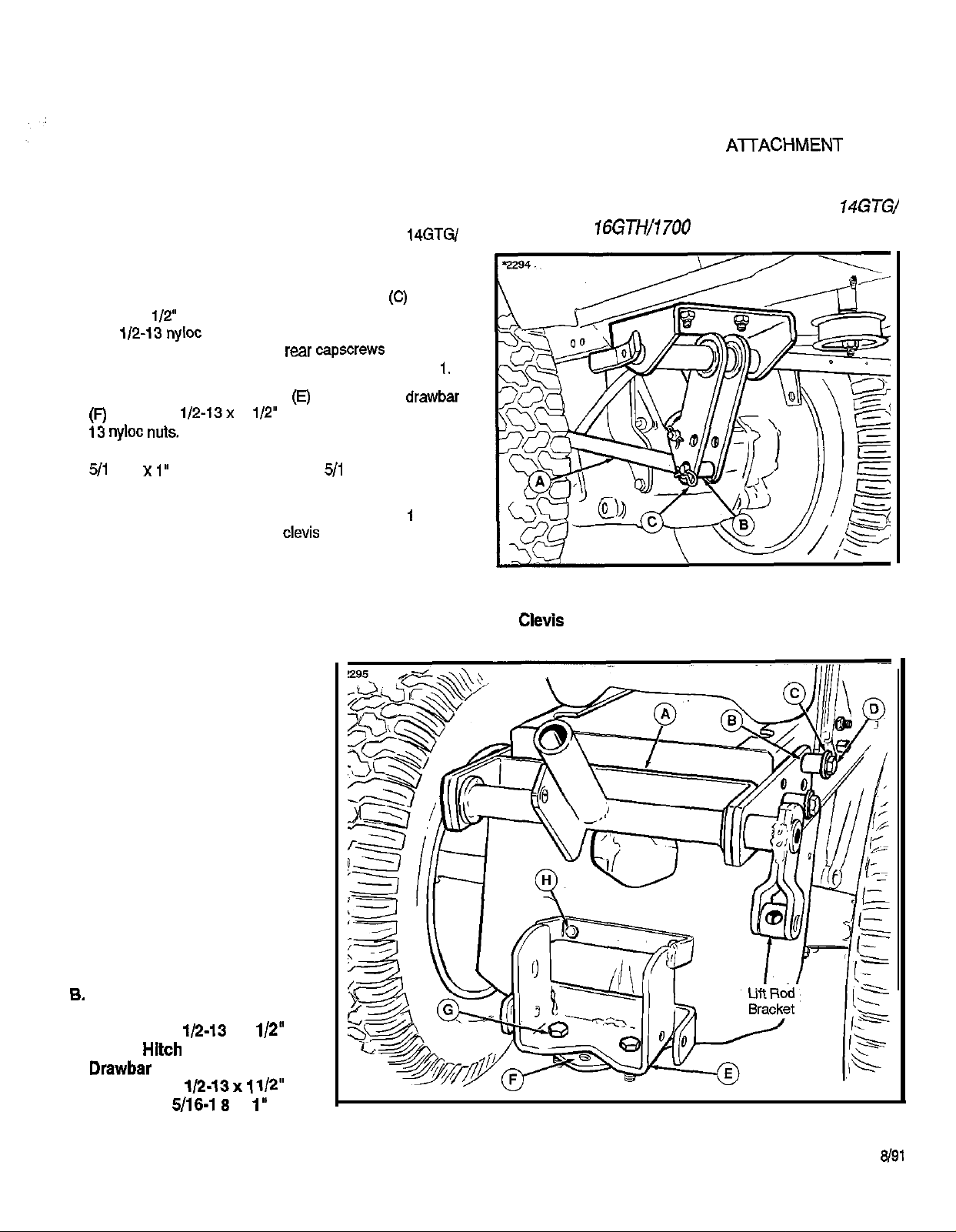
1. Install the upper hitch assembly (A, figure 1) to the rear
tractor frame using four spacers (B), washers
1/2-13x 2 l/2” capscrews (D). Secure on inside of frame
with
in the top frame holes and the
mounted in the bottom frame holes as shown in figure
2. Install the lower hitch assembly (E) to the tractor drawbar
using two
Secure the lower hitch brace to the rear frame using two
6-18 x
3. After the electric lift is installed, the lift rod (A, figure 2) will
be installed to the upper hitch as shown in figure
the lift arm assembly using a
(C) as shown in figure 2.
Note: If tire chains are to be used for tiller operation, rear
wheels should be inverted for additional clearance between
RH wheel/chain and tiller lift rod.
nyloc nuts. The front capscrews are mounted
capscraws are
1 l/2” capscrews (G) and two i/2-
capscrews (H) and two
6 locknuts.
pin (B) and safety clip
and
and to
FIGURE 2. Electric Lift
A. Lift Rod
B. Clevie Pin
C. Safety Clip
REAR
HITCH
MFG. NO. 1692010
FIGURE 1. Rear Hitch
A. Upper Hitch Assembly
Spacers
C. Washers
D. Capscrews,
E. Lower
x 2 l/2”
Assembly
F.
G. Capscrews, 1/2-13x
H. Capscrews, 5116-l 8 x 1”
l/2”
Form 1707679
Printed in USA
Page 2
INSTALLATION
INSTRUCTIONS
REAR ATTACHMENT HITCH
MFG. NO. 1692010
INSTALLATION
Note: Electric
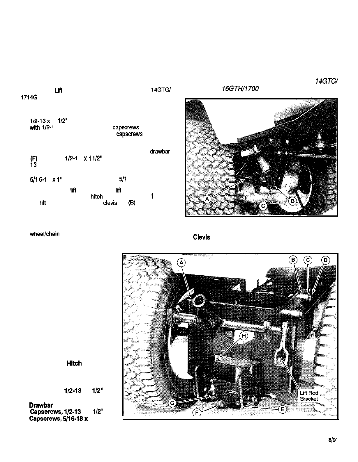
1. Install the upper hitch assembly (A, figure 1) to the rear
tractor frame using four spacers (B), washers (C) and
in the top frame holes and the rear
mounted in the bottom frame holes as shown in figure 1.
2. Install the lower hitch assembly (E) to the tractor drawbar
using two 1/2-l 3 x
Secure the lower hitch brace to the rear frame using two
3. After the electric
be installed to the upper
the
(C) as shown in figure 2.
Note: If tire chains are to be used for tiller operation, rear
wheels should be inverted for additional clearance between
RH
Kit (1692032) must be installed on 14GTG/
2
capscrews (D). Secure on inside of frame
3 nyloc nuts. The front
i/2” capscrews (G) and two i/2-
8 x
capscrews (H) and two
is installed, the
as shown in figure
arm assembly using a
6 locknuts.
rod (A, figure 2) will
pin (6) and safety clip
are mounted
are
and to
FIGURE 2. Electric Lift
A. Lift Rod
B. Clevis Pin
C. Safety Clip
Rear hitch required for mounting tiller to
FIGURE 1. Rear
A. Upper Hitch Assembly
B. Spacers
C. Washers
D. Capscrews,
x 2 l/2”
E. Lower Hitch Assembly
F.
G. Capscrews,
H.
5/16-18x 1”
x 1
Form 1707679
Printed in USA
 Loading...