

Page 1
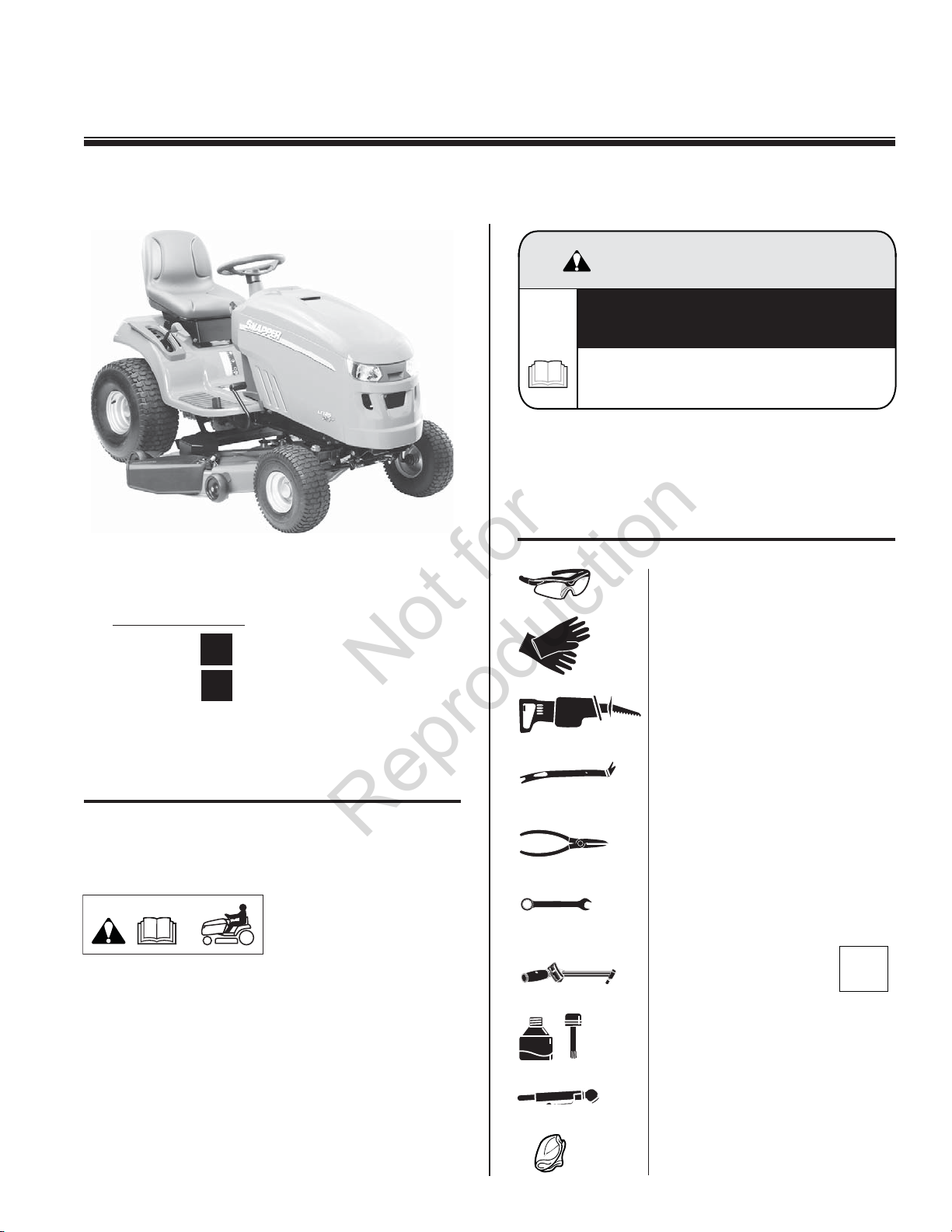
Tractor - Setup Instructions
AVOID SERIOUS INJURY OR DEATH:
Not for
Reproduction
WARNING
AVOID SERIOUS INJURY OR DEATH:
Read and follow the tractor operator
manual before running engine.
Tools
Note: Follow the procedures that apply to your model.
Models
2690945
2690946
42˝
46˝
Attention Setup Personnel:
This unit should NOT be delivered to a customer until
assembly has been completed according to these
instructions.
The safety warnings
provided in this guide and
in the tractor's operator
manual included with the
unit contain important information that must be followed
when assembling, setting-up, operating, servicing,
transporting, or storing the unit.
These warnings are highlighted by the safety alert
triangle symbol shown above, which signifi es that an
important safety message is being provided.
You must read, understand, and follow these warnings
and instructions, and use safe shop and work practices
at all times while working on or around this unit and all
other outdoor power equipment.
ANTI-SEIZE
EYE PROTECTION
WORK GLOVES
CUTTING SAW - packing crate
(optional)
PRY BAR
CUTTING TOOL for tie downs
WRENCHES
7/16˝,1/2˝, 15/16˝
TORQUE WRENCH
ANTI-SEIZE LUBRICANT
TIRE PRESSURE GAUGE
CLOTH (checking oil)
lb-ft
( Nm)
1752827 (REV. -)
Page 2
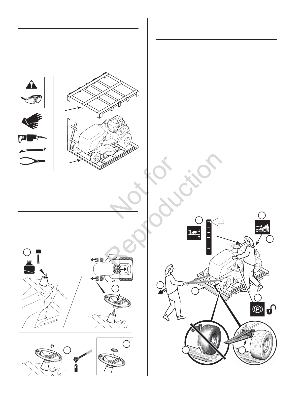
Uncrating
Not for
Reproduction
Using a saw, cut off top crate (a) fi rst, then cut crate
away from bottom pallet (b).
IMPORTANT NOTE: When cutting crate from bottom
pallet, use caution around tractor tires.
a
b
Removing Tractor from
Shipping Pallet
Important: The hydraulic attachment lift and power
steering will not operate when the brake pedal is
engaged. Releasing the brake pedal restores operation.
Important: When the engine is not running, steering
ability is reduced. The tractor can still be maneuvered
by slowly turning the steering wheel.
1. Check to be sure there are no nails or sharp
objects on bottom of skid to puncture the tractor
tires.
2. Place a board in front of the pallet to act as a
step while unloading the tractor.
3. Place mower in the highest height of cut position.
4. Pull the roll release lever until it locks in the
release position.
5. Tap the brake pedal to release the parking brake.
6. Attach a strap or rope on axles as shown.
Assemble Steering Wheel
Note: Apply anti-seize lubricant to the steering shaft.
Then install steering wheel with center spoke facing
down.
1
ANTI-SEIZE
2
7. Pull the tractor off the skid with a second person
guiding it.
8. After moving the tractor, re-engage the roll
release lever by pushing the lever into the drive
position.
3
6
5
4
3
2
1
+
7
2
4
8
5
20 lb-ft (27 Nm)
2
4
3
15/16
1
6
Page 3

Assemble Seat and Switch
Not for
Reproduction
Notes:
Assemble seat to seat support (a).
Fasten seat harness (b) to switch (c).
Fasten tie (d) as shown (zip tie is in literature pack).
2
Charge / Connect Battery
WARNING
RISK OF BATTERY EXPLOSION FROM HYDROGEN
GAS MAY RESULT IN SERIOUS INJURY OR DEATH.
c
b
a
3
d
1
1/2
13 lb-ft
(18 Nm)
Check Oil Level
Note: Engine is shipped with oil, however, oil should be
checked prior to use.
• Tractor should be on a level surface.
• Check oil level on dipstick.
• See Operator's Manual for complete instructions.
• ALWAYS wear safety glasses for your protection
while handling the battery.
• To avoid an explosion, keep fl ames and sparks away
from the battery, especially while charging.
• Battery acid causes severe burns. Avoid contact
with skin.
Battery posts, terminals, and related
accessories contain lead and lead
compounds - chemicals known to the State of
California to cause cancer and reproductive
harm. Wash hands after handling.
Note: If the unit is being put into service after the month
and year indicated on the battery date tag (a) (located
on top of battery) charge the battery before use.
• Remove ignition key.
• Charge battery according to the instructions
provided by the charger manufacturer.
Note: Read and understand any warnings by the
battery manufacturer.
• When charging is complete connect the NEGATIVE
(-) battery cables.
• Coat the cable ends and the battery terminals with
battery terminal protector.
a
( )
7/16
WARNING
COVER
DO NOT REMOVE
APR 11
3
Page 4

Check Tire Pressure Mower Leveling
Not for
Reproduction
Tires are over-infl ated for shipping purposes.
The maximum infl ation is stamped on the sidewall of
the tires. Do not exceed the maximum tire pressure.
The recommended pressures shown below provide
proper traction, improve cut quality, and extended
tire life.
10 psi
(0,68 bar)
12-14 psi
(0,82-0,96 bar)
PREPARATION
WARNING
For your personal safety, do not handle the sharp
mower blades with bare hands. Careless or
improper handling of blades may result in serious
injury.
See Operator's Manual for complete control panel
instructions.
Park tractor on a hard level surface.
Turn front wheels straight.
Place mower approximately in the
middle height of cut position.
Disengage mower blades.
Set parking brake.
Turn ignition OFF and remove key.
Disconnect spark plug wires and
place away from plugs.
4
Page 5

SIDE-to-SIDE LEVELING
Not for
Reproduction
Arrange the blades (two rear blades - 46") so they
are pointing from side-to-side. Using a measuring tool,
measure the distance between the outside tips of each
blade (a / b) and the ground.
FRONT-to-BACK LEVELING
Important: Side-to-side leveling must be performed
fi rst.
The diff erence should be: less than 1/8˝ (3 mm).
IF AN ADJUSTMENT IS NEEDED:
Tighten / loosen nuts (c) (right and left side) as needed
to adjust side-to-side leveling.
MEASURING TOOL - for leveling mower
(4 inch / 100 mm - stiff card board)
a
b
Arrange the blades so they face front to back.
Using a measuring tool, measure:
(a) - the distance between the rear tip of one
of the back blades and the ground.
(b) - the distance between the front tip of the
center blade and the ground.
This should be the same as measurement (a).
b
a
42˝
a
9/16˝
42˝
c
c
b
a
b
ab
46˝
46˝
5
Page 6

42˝
Not for
Reproduction
46˝
IF AN ADJUSTMENT IS NEEDED:
To LOWER front of mower deck (b).
Turn locknuts (c) counterclockwise. Locknuts
must be turned evenly on both sides to keep
deck level (Side-to-Side).
Recheck measurement (b).
To RAISE front of mower deck (b).
Turn locknuts (c) clockwise. Locknuts must be
turned evenly on both sides to keep deck level
(Side-to-Side).
Recheck measurement (b).
IF AN ADJUSTMENT IS NEEDED:
To LOWER the front of mower deck (b).
Turn locknuts (c) counterclockwise. Locknuts
must be turned evenly on both sides to keep deck
level (Side-to Side).
Recheck measurement (b). When correct, turn jam
nuts (d) counterclockwise against the bracket (e) to
secure.
To RAISE front of deck (b).
Turn jam nuts (c) clockwise. Nuts must be turned
evenly on both sides to keep deck level (Side-to
Side). Turn locknuts (d) clockwise against the
spacer / bracket (e) to secure.
Recheck measurement (b).
3/4˝ 3/4˝
b
c
c
3/4˝ 3/4˝
c
c
d
e
c
c
b
e
dd
cc
6
ee
 Loading...