

Page 1

S_PER
0 PERATOR'S
MANUAL
LT-200 Series
20 hp Hydro Tractor
IVlfg.No. Description
2690714 LT2044, 20 hp and 44 in. Mower Deck
44 in. Mower Deck
Mfg. No. Description
1695140 44 in. Mower Deck
CAUTION:Readand
followallinstructions.
ManualPartNo.1734712
RevisionO0
Rev.Date3/2007
TP 100-4516-O0-RG-N
Page 2

Thankyoufor purchasingthis quality-built Snapperproduct. We arepleasedthat you've placedyour confidence in the Snapper
brand. When operatedand maintainedaccording to the instructions in this manual,your Snapperproduct will provide many
years of dependableservice.
Thismanualcontainssafety information to makeyou awareof the hazardsand risks associatedwith lawn careand mowing
products andhow to avoidthem. Thistractor is designedand intended only for lawn careand is not intendedfor any other
purpose. It is important that you readand understand these instructions thoroughly before attempting to start or operate this
equipment. Savethese instructions for future reference.
Someunitsmay requirefinal assemblybeforeuse. Referto the Assemblysection of this manual for instructions on final
assembly procedures. Follow the instructions completely.
Where to Find Us
You can contact SnapperCustomer Service by phone at (888) 477-8650 or on the Internet at snapper.com.Tofind Briggs &
Stratton support and servicefor your engine,consult your Yellow Pages.There are over 30,000 Briggs & Stratton authorized
service dealersworldwide who provide quality service.
Model DescriptionName/Number
Unit Part Number Unit SERIALNumber
Mower DeckPartNumber Mower DeckSERIALNumber
DealerName DatePurchased
Engine Make EngineModel
EngineTypeiSpec EngineCode/SeriesNumber
Note: SeeIdentification Numbers in OperatorSafetysection to locatethis data.
SNAPPER@and SNAPPERPRO@aretrademarks of Briggs & Stratton Yard
Power Group,WI USA.
Snapper Products
535 Macon St.
McDonough, GA30253
Copyright © 2007 Briggs & Stratton Corporation
Milwaukee, WI USA.
All rights reserved.
Page 3

Tableof Contents
OperatorSafety .......................................... 2
Readthe Manual ............................................. 2
Safety Icons................................................. 2
Safety Risks................................................. 3
Safety Rulesand Information ................................... 4
Identification Numbers......................................... 8
Safety Decals................................................ 8
Assembly.............................................. 10
Add Engine Oil.............................................. 10
Add Fuel................................................... 10
Mower Deck Removaland Installation ........................... 10
Controlsand Features..................................... 12
Control Functions............................................ 12
Other Functions............................................. 14
Operation ............................................. 15
Safety InterlockSystem Tests.................................. 15
Adding Fuel................................................ 15
Starting the Engine .......................................... 16
Stopping the Tractor and Engine................................ 16
Driving the Tractor........................................... 16
Mowing ................................................... 16
Lawn Careand Mowing Information ............................. 17
Adjusting Mower Cutting Height ................................ 19
Pushing the Tractorby Hand................................... 19
Attaching aTrailer ........................................... 19
Maintenance ........................................... 21
MaintenanceSchedule........................................ 21
RegularChecks ............................................. 21
Battery Maintenance ......................................... 22
TransmissionMaintenance .................................... 23
Hood Removaland Installation ................................. 23
Tractorand Mower Maintenance................................ 24
Engine Maintenance.......................................... 27
Storage ................................................... 30
Troubleshooting,Adjustment,and Service....................... 31
Troubleshooting............................................. 31
Adjustments................................................ 34
Service.................................................... 35
Warranties............................................. 38
Tractorand Mower DeckWarranty .............................. 38
Parts and Accessories ..................................... 40
Parts ..................................................... 40
TechnicalManuals ........................................... 40
Specifications .................................... BackCover
Page 4
SAVETHESEINSTRUCTIONS
OperatorSafety
Congratulations on purchasinga
superior-quality pieceof lawnand
garden equipment. Our products
are designed and manufacturedto
meet or exceedall industry
standardsfor safety.
Power equipmentis only assafe
asthe operator.If it is misused,or
not properly maintained, it can be dangerous! Remember,
you are responsiblefor your safetyand that of those around
you.
Use common sense, andthink through what you aredoing.
If you are not sure that the task you are aboutto perform
can besafelydone with the equipment you havechosen, ask
a professional: contactyour local authorized dealer.
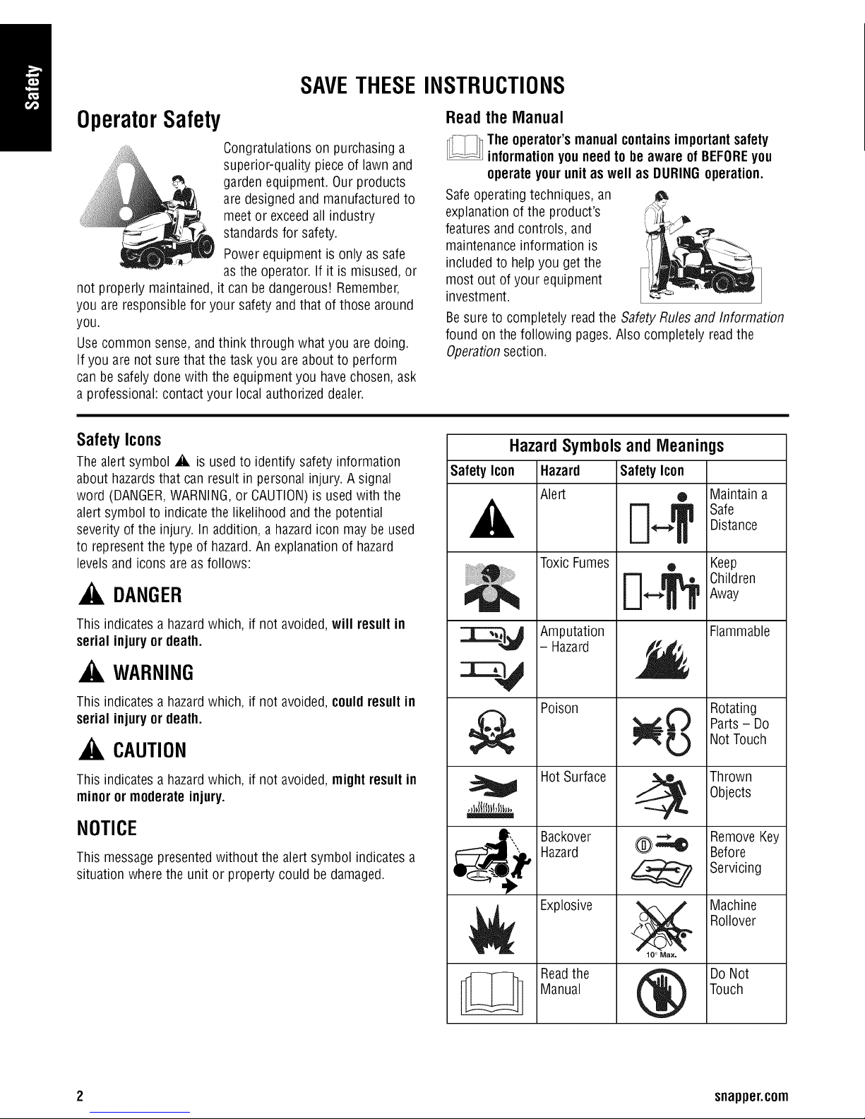
Safety Icons
Thealert symbol A isusedto identify safetyinformation
about hazardsthat can result in personalinjury. Asignal
word (DANGER,WARNING,or CAUTION)is used with the
alert symbol to indicate the likelihood and the potential
severity of the injury. In addition, a hazardicon maybe used
to representthe type of hazard.An explanationof hazard
levels and icons are as follows:
Read the Manual
The operator'smanual containsimportantsafety
informationyouneedto be aware ofBEFOREyou
operateyour unit as well as DURINGoperation.
Safeoperatingtechniques, an
explanation of the product's
featuresand controls, and
maintenanceinformation is
included to helpyou get the
most out of your equipment
investment.
Besureto completely readthe SafetyRules and Information
found onthe following pages.Also completely readthe
Operationsection.
Hazard Symbols and Meanings
Safety Icon Hazard Safety Icon
Alert ® Maintain a
A E] TS '0
ToxicFumes • Keep
Distance
_k, DANGER
This indicatesa hazardwhich, if not avoided,will result in
serial injuryor death.
, WARNING
This indicatesa hazardwhich, if not avoided, couldresult in
serial injuryor death.
_, CAUTION
This indicatesa hazardwhich, if not avoided, mightresult in
minor or moderateinjury.
NOTICE
This messagepresentedwithout the alert symbol indicatesa
situation where the unit or property could be damaged.
j'_ _.._1_ I ChildrenAway
Amputation Flammable
- Hazard
Poison
Hot Surface
Backover
Hazard
Explosive
Rotating
Parts- Do
Not Touch
Thrown
Objects
RemoveKey
Before
Servicing
Machine
Rollover
N
Readthe
Manual
®
DoNot
Touch
2 snapper.corn
Page 5
Safety Risks
Children
Tragicaccidents can occur with
children. Do not allow them
anywhere nearthe area of
operation. Children are often
attracted to the unit and
mowing activity. Neverassume
that children will remainwhereyou last saw them. If there is
a risk that children mayenterthe areawhereyou are
mowing, haveanother responsible adult watch them.
DONOTGIVECHILDRENRIDESONTHIS UNIT! This
encouragesthem to come near the unit inthe future while it
is running, and they could be seriously hurt. They may then
approachthe unit for a ride whenyou arenot expecting it,
and you may run over them.
Reverse
Do not mow in reverseunless
absolutely necessary.Always
look down andbehind beforeand
while traveling in reverseeven
with the mower blades
disengaged.
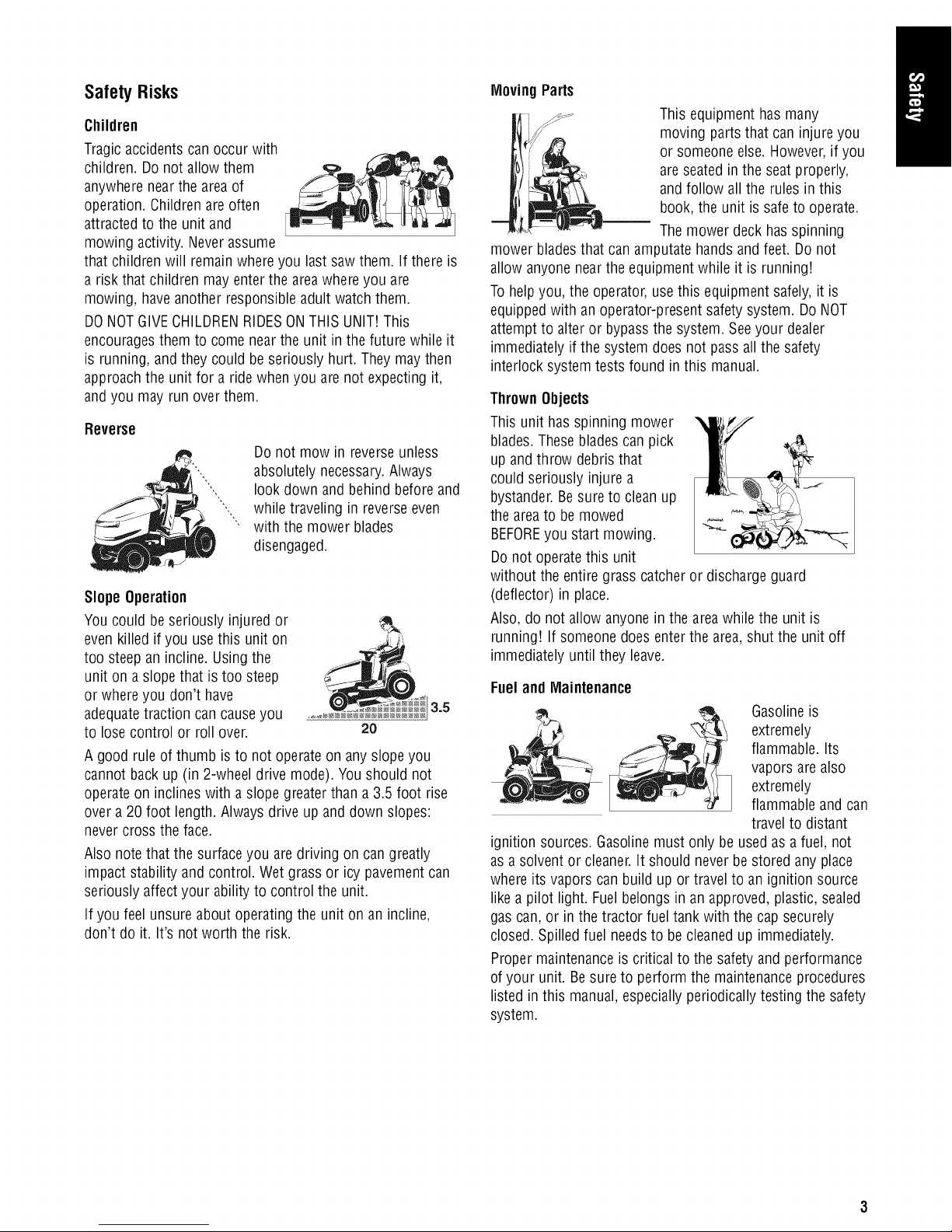
SlopeOperation
You could be seriously injured or
evenkilled if you usethis unit on
too steepan incline. Using the
unit ona slope that is too steep
or whereyou don't have
adequatetraction can causeyou
to losecontrol or roll over.
A good rule of thumb is to not operate on any slope you
cannot back up(in 2-wheeldrive mode).You should not
operateon inclines with aslope greaterthan a3.5 foot rise
over a20 foot length. Alwaysdrive upand down slopes:
nevercross the face.
Also note thatthe surfaceyou are driving on can greatly
impact stability and control. Wet grass or icy pavementcan
seriously affectyour ability to control the unit.
If you feel unsure about operating the unit on an incline,
don't do it. It's not worth the risk.
2O
MovingParts
This equipment has many
moving parts that can injureyou
or someone else.However,if you
are seated inthe seat properly,
and follow all the rules in this
book, the unit is safeto operate.
Themower deck has spinning
mower bladesthat can amputatehands and feet. Do not
allow anyone nearthe equipmentwhile it is running!
Tohelp you, the operator, usethis equipment safely, it is
equipped with anoperator-present safetysystem. Do NOT
attempt to alter or bypassthe system. Seeyour dealer
immediately if the system does not passall the safety
interlock systemtests found in this manual.
ThrownObjects
This unit has spinning mower
blades. Theseblades can pick
up andthrow debristhat
could seriously injure a
bystander. Besure to clean up
the areato bemowed
BEFOREyou start mowing.
Donot operatethis unit
without the entire grass catcheror discharge guard
(deflector) in place.
Also, do not allow anyonein the areawhile the unit is
running! If someone doesenter the area,shut the unit off
immediately until they leave.
Fueland Maintenance
Gasolineis
extremely
flammable. Its
vapors are also
extremely
flammable andcan
travel to distant
ignition sources.Gasolinemust only be used as afuel, not
as asolvent or cleaner.It should neverbe stored any place
where its vapors can build up or travel to an ignition source
like apilot light. Fuel belongs in an approved, plastic, sealed
gas can,or in the tractor fuel tank with the cap securely
closed. Spilledfuel needsto be cleaned up immediately.
Proper maintenanceis critical to the safety andperformance
of your unit. Besure to perform the maintenance procedures
listed in this manual,especiallyperiodically testing the safety
system.
Page 6
Safety Rules and Information
WARNING
Readthesesafetyrules andfollow themclosely.
Failureto obeytheserules couldresult in lossof
controlof unit, severepersonalinjuryor deathto
you,or bystanders,or damageto propertyor
equipment.
Thismowingdeckis capable of amputatinghands
andfeet and throwingobjects.
GeneralOperation
1. Read, understand,and follow all instructions in the
manual andon the unit before starting.
2. Do not put hands or feet near rotating parts or under
the machine. Keepclearof the discharge opening at all
times.
3. Only allow responsibleadults, who arefamiliar with the
instructions, to operatethe unit (local regulations can
restrict operator age).
4. Clearthe areaof objects such as rocks, toys, wire, etc.,
which could be picked up andthrown bythe blade(s).
5. Be sure the areais clear of other peoplebefore
mowing. Stop the unit if anyoneenters the area.
6. Never carry passengers.
7. Do not mow in reverseunless absolutely necessary.
Always look down and behind before and while
travelling in reverse.
8. Never direct dischargematerialtoward anyone.Avoid
discharging material againsta wall or obstruction.
Material may ricochet backtoward the operator. Stop
the blade(s)when crossing gravel surfaces.
9. Do not operatethe machinewithout the entire grass
catcher,discharge guard (deflector), or other safety
devices inplace.
10. Slow down beforeturning.
11. Never leavea running unit unattended.Always
disengagethe PTO,set parking brake, stop engine,and
remove keys before dismounting.
12. Disengageblades(PTO)when not mowing. Shut off
engine and wait for all parts to come to a complete stop
before cleaningthe machine, removing the grass
catcher,or unclogging the discharge guard.
13. Operatethe machineonly in daylight or good artificial
light.
14.
Do not operatethe unit while underthe influenceof
alcohol or drugs.
15.
Watchfor traffic when operating near or crossing
roadways.
16.
Use extra carewhen loading or unloadingthe unit into
a trailer or truck.
17.
Alwayswear eyeprotection when operatingthis unit.
18.
Data indicates that operators, age 60years and above,
are involved ina large percentageof power equipment-
related injuries.These operatorsshould evaluatetheir
ability to operate the equipment safely enoughto
protect themselves andothers from injury.
19. Follow the manufacturer's recommendations for wheel
weights or counterweights.
20. Keepin mind the operator is responsiblefor accidents
occurring to other peopleor property.
21. All drivers should seek and obtain professional and
practical instruction.
22. Alwayswear substantial footwear and trousers. Never
operatewhen barefootor wearing sandals.
23. Before using, always visually checkthat the bladesand
blade hardware are present, intact, and secure. Replace
worn or damagedparts.
24. Disengageattachments before: refueling, removing an
attachment, making adjustments (unless the
adjustment can be made from the operator's position).
25. Whenthe machineis parked, stored, or left unattended,
lower the cutting meansunless a positive mechanical
lock is used.
26. Before leavingthe operator's position for any reason,
engagethe parking brake (if equipped),disengagethe
PTO,stop the engine,and removethe key.
27. Toreducefire hazard,keepthe unit free of grass,
leaves,and excessoil. Do not stop or parkover dry
leaves,grass, or combustible materials.
28. It is a violation of California Public ResourceCode
Section 4442 to useor operatethe engine on or near
anyforest-covered, brush-covered, or grass-covered
land unlessthe exhaustsystem is equippedwith a
spark arrester meetingany applicablelocal or state
laws. Other statesor federal areasmay have similar
laws.
4 snapper.corn
Page 7
TransportingandStorage
1. When transporting the unit on an open trailer, make
sure it is facing forward, in the direction of travel. If the
unit is facing backwards,wind lift could damagethe
unit.
2. Always observesafe refueling andfuel handling
practices when refuelingthe unit after transportation or
storage.
3. Never store the unit (with fuel) in anenclosed poorly
ventilatedstructure. Fuelvapors can travel to an
ignition source (such as a furnace, water heater,etc.)
and cause anexplosion. Fuelvapor is also toxic to
humans and animals.
4. Alwaysfollow the engine manual instructions for
storage preparations beforestoring the unit for both
short and longterm periods.
5. Alwaysfollow the engine manual instructions for proper
start-up procedureswhen returning the unit to service.
6. Never store the unit or fuel container insidewhere there
is anopen flameor pilot light, such as in awater
heater.Allow unit to cool before storing.
SlopeOperation
Slopes area major factor relatedto loss-of-control and
tip-over accidents, which can result insevere injury or death.
Operationon all slopesrequires extra caution. Ifyou cannot
back up the slope or if you feel uneasyon it, do not operate
on it.
Control of a walk-behind or ride-on machinesliding on a
slope will not be regainedby the application of the brake.
The main reasonsfor loss of control are: insufficient tire grip
on the ground, speedtoo fast, inadequatebraking, the type
of machineis unsuitablefor its task, lackof awareness of the
ground conditions, incorrect hitching and loaddistribution.
1. Mow up and down slopes, not across.
2. Watchfor holes, ruts, or bumps. Uneventerrain could
overturn the unit. Tall grass can hideobstacles.
3. Choosea slow speed so thatyou will not haveto stop
or changespeedswhile on the slope.
4. Do not mowon wet grass. Tires may loose traction.
5. Always keepunit in gear especiallywhen traveling
down slopes. Donot shift to neutral and coast downhill.
6. Avoid starting, stopping, or turning on a slope. If tires
lose traction, disengagethe blade(s) and proceed
slowly straight down the slope.
7. Keepall movement on slopes slow andgradual. Donot
make sudden changes in speedor direction, which
could causethe machine to rollover.
8. Use extra care while operating machineswith grass
catchers or other attachments; they can affect the
stability of the unit. Do not useon steepslopes.
9. Do not try to stabilize the machine by putting your foot
on the ground (ride-on units).
10. Do not mow near drop-offs, ditches, or embankments.
The mowercould suddenly turn over if awheel is over
the edgeof acliff or ditch, or if an edgecavesin.
11. Do not usegrass catchers onsteep slopes.
12. Do not mow slopes if you cannot back up them.
13. Seeyour authorizeddealer/retailerfor
recommendations of wheel weights or counterweights
to improvestability.
14. Remove obstacles suchas rocks, tree limbs, etc.
15. Use slow speed.Tires maylosetraction on slopes even
though the brakesare functioning properly.
16. Do not turn on slopes unlessnecessary,and then,turn
slowly andgradually downhill, if possible.
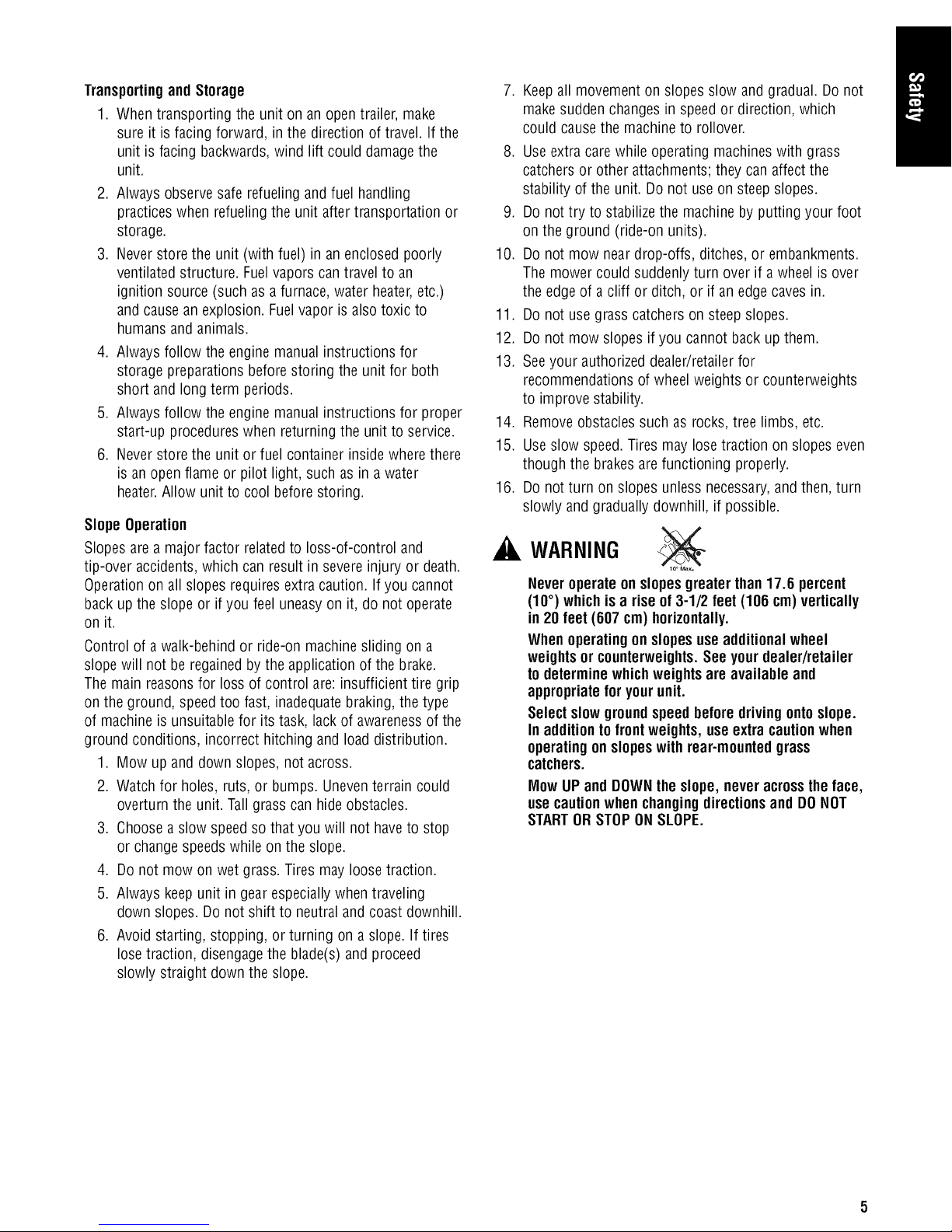
WARNING
Neveroperateonslopesgreaterthan17.6 percent
(10°) whichisa rise of3-1/2 feet (106 cm)vertically
in 20 feet(607 cm) horizontally.
Whenoperatingonslopesuseadditional wheel
weightsor counterweights.Seeyourdealer/retailer
todeterminewhichweightsare available and
appropriateforyourunit.
Selectslowgroundspeedbeforedrivingontoslope.
In additionto frontweights, useextra cautionwhen
operatingonslopeswith rear-mountedgrass
catchers.
Mow UP and DOWNtheslope, neveracrossthe face,
usecautionwhen changingdirectionsand DONOT
STARTORSTOPONSLOPE.
Page 8

TowedEquipment(Ride-On Units)
1. Tow only with a machinethat hasa hitch designedfor
towing. Do not attach towed equipment exceptat the
hitch point.
2. Follow the manufacturer's recommendations for weight
limit for towed equipment andtowing on slopes.
3. Never allow children or others in or on towed
equipment.
4. On slopes, the weight of the towed equipment may
cause loss of traction and loss of control.
5. Travelslowly and allow extra distance to stop.
6. Do not shift to neutral and coast down hill.
Children
Tragicaccidents can occur if the operator is not alertto the
presenceof children. Childrenare often attractedto the unit
and the mowing activity. Neverassumethat children will
remain whereyou last saw them.
1. Keepchildren out of the mowing areaand underthe
watchful care of another responsible adult.
2. Be alert and turn unit off if children enterthe area.
.
Beforeand during reverseoperation, look behind and
down for small children.
4.
Never carry children, evenwith the blade(s) off. They
may fall off and beseriously injured or interfere with
safe unit operation. Children who havebeen given rides
in the past may suddenly appear inthe mowing areafor
another ride and be run over or backed over bythe
machine.
5. Never allow children to operatethe unit.
6. Use extra carewhen approaching blind corners, shrubs,
trees, or other objects that may obscurevision.
Emissions
1. Engineexhaust from this product contains chemicals
known, incertain quantities, to causecancer,birth
defects,or other reproductiveharm.
2. Look for the relevant Emissions Durability Period and
Air Index information on the engine emissions label.
IgnitionSystem
1. This spark ignition system complies with Canadian
ICES-O02.
Serviceand Maintenance
SafeHandling of Gasoline
1. Extinguish all cigarettes, cigars, pipes, andother
sources of ignition.
2. Use only approved gasolinecontainers.
3. Never removethe gascap or addfuel with the engine
running. Allow the engine to cool before refueling.
4. Neverfuel the machineindoors.
5. Neverstore the machine or fuel container wherethere
is an openflame, spark, or pilot light suchas neara
water heateror other appliance.
6. Neverfill containers inside avehicle or on a truck bed
with a plastic bed liner. Always place containers on the
ground away from your vehiclebeforefilling.
7. Remove gas-powered equipmentfrom the truck or
trailer and refuel it on the ground. Ifthis is not
possible,then refuel such equipmenton atrailer with a
portable container, ratherthan from a gasoline
dispenser nozzle.
8. Keepnozzle in contact with the rim of the fuel tank or
container opening at all times until fueling is complete.
Do not usea nozzlelock-open device.
9. If fuel is spilled on clothing, changeclothing
immediately.
10. Neverover-fill the fuel tank. Replacegascap and
tighten securely.
11. Use extra care in handling gasolineand other fuels.
They areflammable and vapors are explosive.
12. If fuel is spilled, do not attemptto start the engine but
move the machineaway from the areaof spillage and
avoid creatingany source of ignition until fuel vapors
havedissipated.
13. Replaceall fuel tank capsand fuel containercaps
securely.
6 snapper.corn
Page 9

Service and Maintenance
1. Never run the unit inan enclosed areawhere carbon
monoxide fumes may collect.
2. Keepnuts and bolts, especiallyblade attachment bolts,
tight and keep equipment in good condition.
3. Nevertamper with safetydevices. Checktheir proper
operation regularly andmake necessary repairs if they
are not functioning properly.
4. Keepunit free of grass, leaves, or other debris build-up.
Cleanup oil or fuel spillageand remove anyfuel-soaked
debris. Allow machine to cool before storage.
5. If you strike an object, stop and inspectthe machine.
Repair,if necessary,before restarting.
6. Never makeadjustments or repairswith the engine
running.
7. Checkgrass catcher components andthe discharge
guard frequently and replace with manufacturer's
recommendedparts,when necessary.
8. Mower blades are sharp.Wrap the bladeor wear
gloves, anduse extra caution when servicing them.
9. Checkbrakeoperation frequently.Adjust andservice as
required.
10. Maintain or replacesafety and instructions labels,as
necessary.
11. Do not removethe fuel filter when the engineis hot as
spilled gasoline mayignite. Donot spreadfuel line
clamps further than necessary.Ensureclamps grip
hoses firmly over the filter after installation.
12. Do not usegasolinecontaining METHANOL,gasohol
containing more than 10% ETHANOL,gasoline
additives, or white gas becauseengine/fuel system
damagecould result.
13. If the fuel tank must be drained, it should be drained
outdoors.
14. Replacefaulty silencers/mufflers.
15. Use only factory authorized replacement parts when
making repairs.
16. Always comply with factory specificationson all
settings and adjustments.
17. Only authorizedservice locations should be utilized for
major serviceand repairrequirements.
18. Neverattempt to make major repairson this unit unless
you havebeen properly trained. Improper service
procedures can result in hazardousoperation,
equipment damage and voiding of manufacturer's
warranty.
19. On multiple blade mowers, take care as rotating one
blade can causeother bladesto rotate.
20. Do not changeengine governor settings or over-speed
the engine.Operating the engine at excessive speed can
increasethe hazardof personal injury.
21. Disengagedrive attachments, stop the engine,remove
the key,and disconnectthe spark plug wire(s) before:
clearing attachment blockagesand chutes,performing
servicework, striking an object, or if the unit vibrates
abnormally.After striking an object, inspectthe
machine for damageand make repairs before restarting
and operating the equipment.
22. Never place hands nearthe moving parts, such as a
hydro pump cooling fan, when the tractor is running.
(Hydro pump cooling fans aretypically locatedon top
of the transaxle.)
23. Units with hydraulic pumps, hoses, or motors:
WARNING:Hydraulicfluid escapingunder pressure
may havesufficient force to penetrateskin andcause
serious injury. If foreign fluid is injected into the skin it
must besurgically removedwithin a few hours by a
doctor familiar with this form of injury or gangrene may
result. Keepbody and hands awayfrom pin holes or
nozzlesthat eject hydraulic fluid under high pressure.
Use paper or cardboard, and not hands,to searchfor
leaks.Make sure all hydraulic fluid connections are
tight and all hydraulichoses and linesare ingood
condition beforeapplying pressureto the system. If
leaks occur, havethe unit serviced immediately byyour
authorized dealer.
24. WARNING:Stored energydevice. Improper releaseof
springs can result in serious personalinjury. Springs
should beremoved by an authorizedtechnician.
25. Models equippedwith an engine radiator: WARNING:
Stored energydevice. To prevent seriousbodily injury
from hot coolant or steam blow-out, neverattempt to
remove the radiatorcap while the engineis running.
Stop the engineand wait until it is cool. Eventhen, use
extremecare when removingthe cap.
Page 10
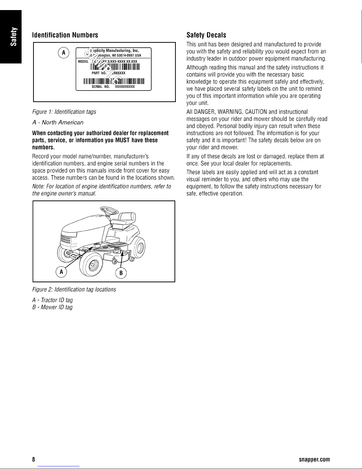
Identification Numbers
I \_._L_hi.g_°,,w153o74-og97usa
Figure 1:Identificationtags
A - North American
Whencontactingyourauthorizeddealer for replacement
parts,service, or informationyouMUSThavethese
numbers.
Recordyour model name/number,manufacturer's
identification numbers, and engineserial numbers in the
space provided on this manualsinside front cover for easy
access.Thesenumbers can befound in the locations shown.
Note: Forlocation of engine identification numbers, refer to
the engineowner's manual.
Safety Decals
This unit has beendesigned and manufactured to provide
you with the safety and reliability you would expectfrom an
industry leaderin outdoor power equipmentmanufacturing.
Although readingthis manualand the safety instructions it
contains will provide you with the necessarybasic
knowledge to operatethis equipment safely andeffectively,
we haveplaced several safetylabelson the unit to remind
you of this important information while you areoperating
your unit.
All DANGER,WARNING,CAUTIONand instructional
messageson your rider andmower should be carefully read
and obeyed. Personalbodily injury can result when these
instructions are not followed. The information is for your
safety and it is important! Thesafety decals below areon
your rider and mower.
If any of these decals are lost or damaged,replacethem at
once. Seeyour local dealerfor replacements.
Theselabelsare easily appliedand will act as aconstant
visual reminderto you, and others who mayusethe
equipment, to follow the safetyinstructions necessaryfor
safe,effective operation.
Figure2: Identification tag locations
A - TractorID tag
B - Mower IDtag
8 snapper.corn
Page 11
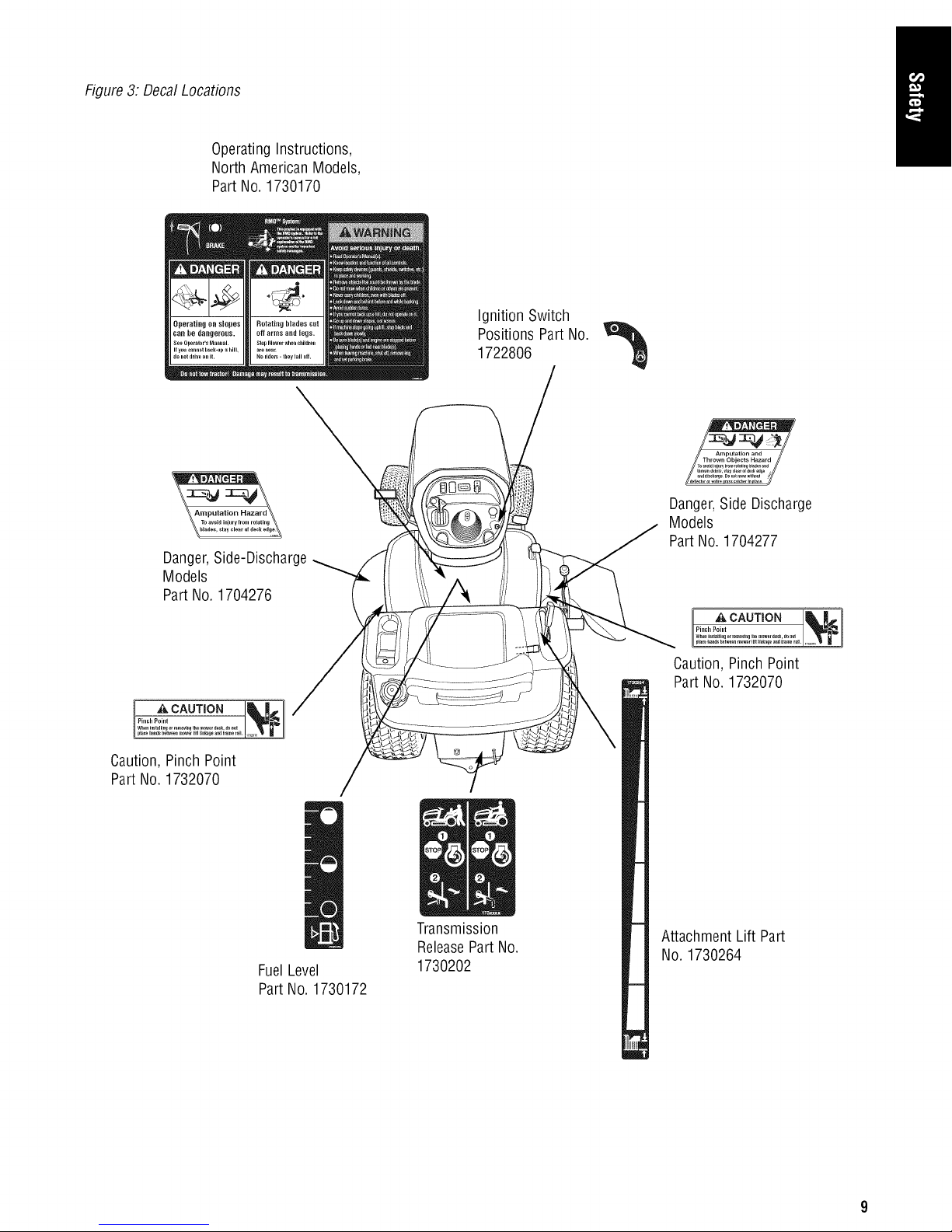
Figure3: DecalLocations
OperatingInstructions,
North American Models,
Part No.1730170
Danger,Side-Discharge
Models
Part No.1704276
Ignition Switch
Positions PartNo.
1722806
Danger,Side Discharge
Models
Part No.1704277
i ACAUTIONILR.]I
Pinch Point u_
I ACAUTIO._.!.
Caution, Pinch Point
Part No.1732070
FuelLevel
Part No.1730172
Transmission
ReleasePart No.
1730202
Caution,Pinch Point
Part No. 1732070
Attachment Lift Part
No. 1730264
Page 12
Assembly
NOTICE
DONOTattemptto start the engine beforeit has been
properlyservicedwith therecommendedoil. This
may result in anenginefailure.
Add Engine Oil
Refer to ChangeEngine Oilin the Maintenancesection for oil
type and fill procedures.
Add Fuel
Refer to Adding Fuelin the Operationsectionfor fuel
specifications andfilling procedures.
Mower Deck Removal and Installation
WARNING
Engageparkingbrake, disengagePTO, stopengine
and removekey beforeattemptingto install or
removethemower.
CAUTION
The mufflerand surroundingareas may be hot.
6. Turn wheels straight ahead.Support the mower hanger
(C). Removesafety clip (A, Figure6) and rod (B).
Lower the mower hanger (C).
7. Turn wheels fully left, andslide mower deck out right
side of tractor.
Installingthe MowerDeck
1. Park tractor, shut off PTOand engine, removethe key
and apply parking brake. Turn the wheels fully to the
left.
2. Placethe mower lift lever(A, Figure7) in the lowest
position. Slidemower deck under right sideof tractor
so that mower hitch is alignedwith the front tractor
hitch.
3. Turn wheels straight. Lift the mower hanger (C,
Figure6). Insert rod (B)through mower hanger (C) and
tractor brackets(D). Secure with safetyclip (A).
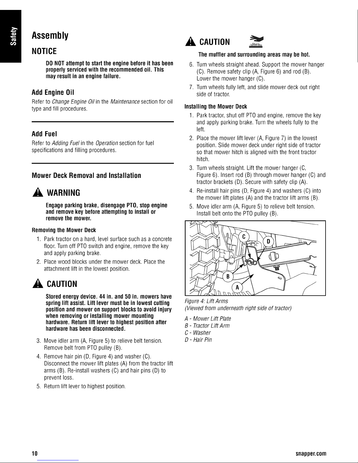
4. Re-install hair pins (D, Figure4) and washers (C) into
the mower lift plates (A) and the tractor lift arms (B).
5. Move idlerarm (A, Figure5) to relievebelt tension.
Install belt onto the PTOpulley (B).
Removingthe Mower Deck
1. Park tractor on a hard, levelsurface such as a concrete
floor. Turnoff PTOswitch and engine, removethe key
and apply parking brake.
2. Placewood blocks underthe mower deck. Placethe
attachment lift in the lowest position.
CAUTION
Storedenergydevice.44 in. and50 in. mowershave
springlift assist. Lift levermustbe in lowestcutting
positionand moweronsupportblocksto avoidinjury
whenremovingor installingmowermounting
hardware.Returnlift lever tohighestpositionafter
hardwarehasbeendisconnected.
3. Move idler arm (A, Figure 5) to relieve belt tension.
Removebelt from PTOpulley (B).
4. Removehair pin (D, Figure4) and washer (C).
Disconnectthe mower lift plates (A) from the tractor lift
arms (B). Re-installwashers (C) andhair pins (D) to
prevent loss.
5. Return lift leverto highest position.
Figure4: Lift Arms
(Viewedfrom underneathright side of tractor)
A - Mower Lift Plate
B - TractorLift Arm
C- Washer
D- Hair Pin
10 snapper.corn
Page 13
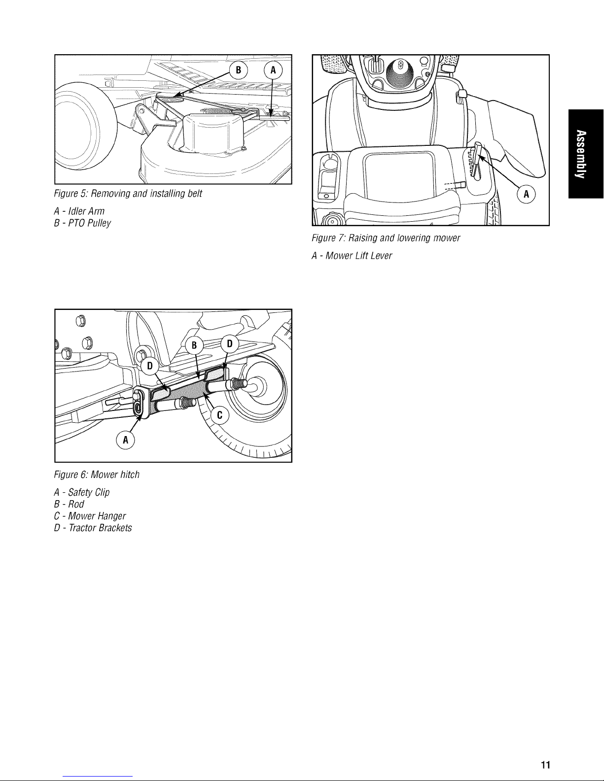
Figure5: Removingand installing belt
A - Idler Arm
B- PTOPulley
Figure 6: Mower hitch
Figure 7. Raisingand lowering mower
A - Mower Lift Lever
A- SafetyClip
B - Rod
C - Mower Hanger
D - TractorBrackets
11
Page 14
ControlsandFeatures
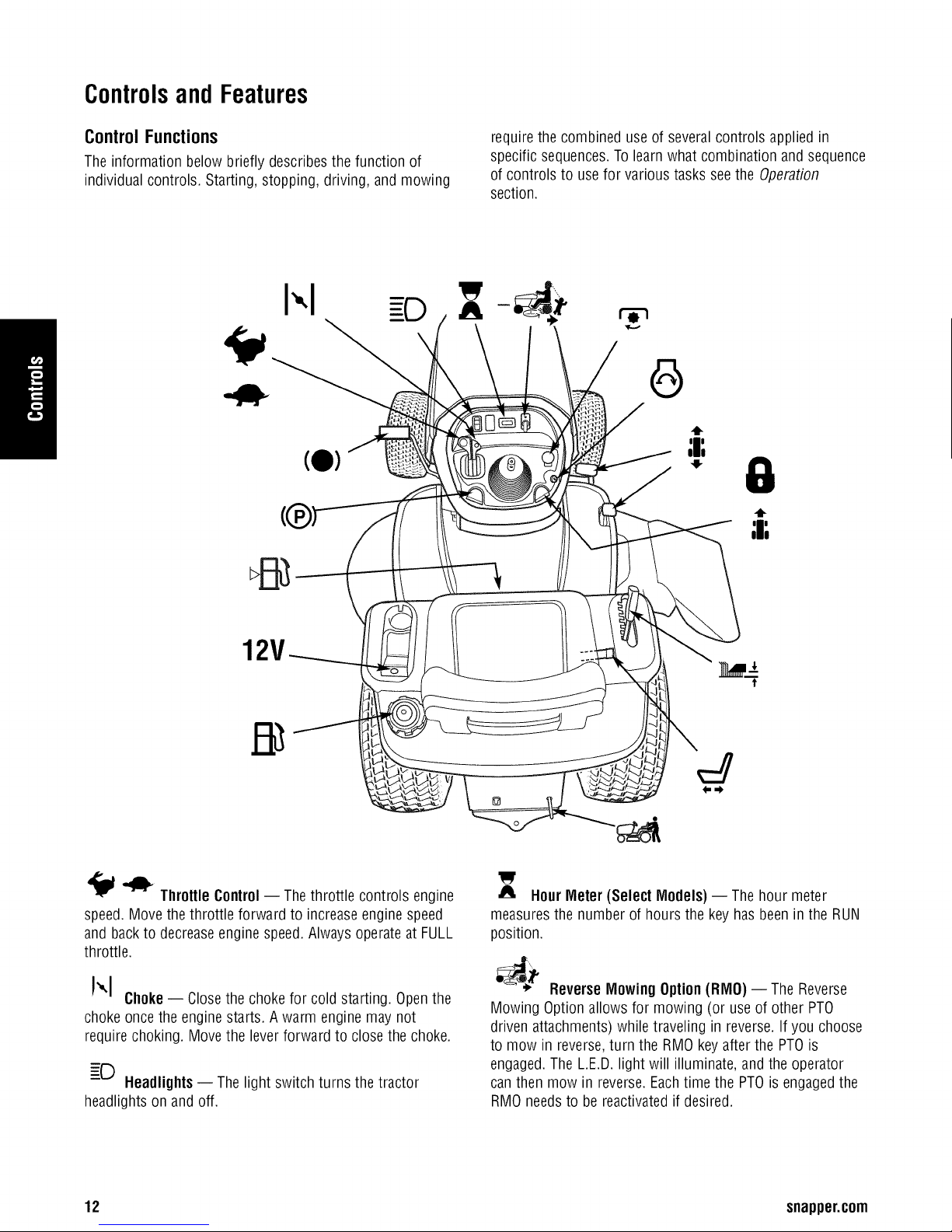
Control Functions
The information below briefly describesthe function of
individual controls. Starting, stopping, driving, and mowing
I',1 -D ^
requirethe combined use of several controls applied in
specific sequences.To learn what combination andsequence
of controls to usefor various tasks seethe Operation
section.
W
Throttle Control-- Thethrottle controls engine
speed. Move thethrottle forward to increase enginespeed
and backto decreaseengine speed. Alwaysoperate at FULL
throttle.
!",1 Choke-- Closethe choke for cold starting. Openthe
choke once the enginestarts. Awarm engine may not
require choking. Move the leverforward to close the choke.
Headlights-- The light switch turns the tractor
headlights on andoff.
12 snapper.com
HourMeter (Select Models) -- The hour meter
measuresthe number of hours the key has been inthe RUN
position.
;_ ReverseMowing Option(RMO) -- The Reverse
Mowing Option allows for mowing (or useof other PTO
driven attachments)while traveling in reverse. If you choose
to mow in reverse,turn the RMO keyafter the PTOis
engaged.The L.E.D.light will illuminate, and the operator
canthen mow in reverse.Eachtime the PTOis engagedthe
RMOneedsto bereactivatedif desired.
Page 15
PTOSwitch- The PTO(PowerTake-Off)switch
engagesand disengagesattachments that usethe PTO.To
engagethe PTO,pull UPon the switch. Push DOWNto
disengage.Note that the operator must be seatedfirmly in
the tractor seatfor the PTOto function.
1_) Ignition Switch-- The ignition switch starts and
stops the engine, it hasthree positions:
©
0
OFF
RUN
START
Stops the engine andshuts offthe electrical
system.
Allows the engine to run andpowers the
electricalsystem.
Cranksthe enginefor starting.
J-- Seat AdjustmentLever-- The seat can beadjusted
forward and back. Movethe lever,position the seat as
desired, and releasethe leverto lockthe seatinto position.
TransmissionReleaseValve Lever -- The
transmission releasevalve lever deactivatesthe transmission
so thatthe tractor can be pushed by hand. See Pushing the
Tractorby Handin the Operationsection for operational
information.
Pa
•-'_ Fuel Tank-- Toremove the cap, turn
counterclockwise.
12V
Power Outlet(Select Models) -- Thepower outlet is
12V-DC.Accessory must be ratedat 9 amps or less.
NOTICE
Never leave the ignition switchin the RUN position
withthe enginestopped- thisdrainsthe battery.
4_
;I;
* GroundSpeed Pedals-- Thetractor's forward
ground speedis controlled by the forward ground speed
control pedal.Thetractor's reverse ground speedis
controlled by the reverseground speedcontrol pedal.
Depressingeither pedalwill increaseground speed.Note
that thefurther down the pedalis depressed,the faster the
tractor will travel.
;_ CruiseControl-- Thecruise control is usedto
lock the ground speed control in forward. The cruise control
hasfive lock positions.
_e,4 Mower HeightofCutAdjustment-- The mower
cutting height adjustment levercontrols the mower cutting
height. Themower cutting height can be set to oneof seven
positions between1-1/4 and4 in.
'' Fuel LevelGauge -- Displaysthe fuel levelin the
tank.
ParkingBrake--The parking brake knob is usedto
lock the parking brakewhen the tractor is stopped. Fully
depressingthe brake pedaland pulling up on the knob
engagesthe parking brake. Referto Parking BrakeFunction
below for afull explanation.
(0)
BrakePedal- Depressingthe brake pedalapplies
the tractor brake.
13
Page 16
Other Functions
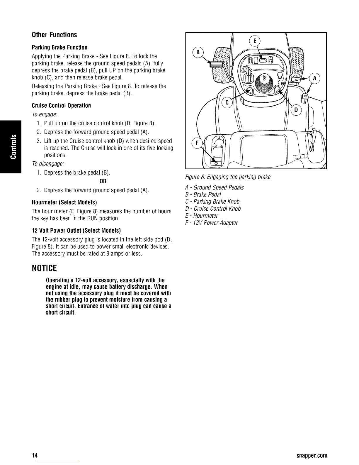
ParkingBrakeFunction
Applying the ParkingBrake- SeeFigure 8. To lock the
parking brake, releasethe ground speedpedals(A), fully
depress the brakepedal (B), pull UPon the parking brake
knob (C), and then release brake pedal.
Releasingthe Parking Brake- SeeFigure8. To releasethe
parking brake,depress the brake pedal (B).
CruiseControlOperation
Toengage:
1. Pull up on the cruise control knob (D, Figure8).
2. Depressthe forward ground speed pedal (A).
3. Lift up the Cruise control knob (D) when desired speed
is reached.The Cruisewill lock inone of its five locking
positions.
Todisengage:
1. Depressthe brake pedal(B).
OR
2. Depressthe forward ground speed pedal (A).
Hourmeter (Select Models)
The hourmeter (E, Figure8) measuresthe number of hours
the keyhas been in the RUNposition.
12 Volt Power Outlet(Select Models)
The 12-volt accessoryplug is located in the leftside pod(D,
Figure8). It can beusedto power small electronic devices.
Theaccessory must berated at 9 ampsor less.
Figure8: Engagingthe parking brake
A - GroundSpeedPedals
B - BrakePedal
C- Parking BrakeKnob
D- Cruise Control Knob
E- Hourmeter
F - 12VPowerAdapter
NOTICE
Operatinga 12-volt accessory,especiallywith the
engineat idle, may causebatterydischarge.When
notusingthe accessoryplug it mustbe coveredwith
therubberplugto preventmoisturefrom causinga
shortcircuit. Entranceofwater into plugcan causea
shortcircuit.
14 snapper.corn
Page 17
Operation
SafetyInterlockSystemTests
WARNING
Thisunitis equippedwithsafetyinterlockswitches
and othersafetydevices.Thesesafetysystemsare
presentforyoursafety:do notattemptto bypass
safetyswitches,andnevertamper withsafety
devices.Checktheir operationregularly.
Your unit is equippedwith a seatswitch safety system.
Checkthe seatswitch operation everyfall and spring with
the following tests.
TestI -- Engine
• PTOswitch
• Brakepedal
Test2 -- Engine
• PTOswitch
• Brakepedal
shouldNOTcrankif:
is ON,OR
is NOTfully depressed(parking brakeOFF),
SHOULDcrankif:
isOFF,AND
isfully depressed(parking brakeON)
, WARNING
Gasolineishighlyflammable andmustbe handled
with care. Neverfill the tank whenthe engineis still
hotfrom recentoperation.Do notallow openflame,
smokingor matchesin the area. Avoidover-filling
andwipe up anyspills.
NOTICE Q
Do notuse gasolinecontainingMETHANOL,gasohol
containingmorethan 10% ETHANOL,gasoline
additives,orwhite gas becauseengine/fuelsystem
damagecouldresult.
Adding Fuel
Toadd fuel:
1. Remove the fuel cap (A, Figure10).
2. Fill the tank. Do not overfill. Leaveroom inthe tank for
fuel expansion. Referto your engine manual for specific
fuel recommendations.
3. Install and hand tighten the fuel cap.
Test3 -- EngineshouldSHUTOFFif:
• Operator rises off seat with PTOengaged,OR
• Operator rises off seat with brakepedal NOTfully
depressed (parking brakeOFF).
Test4 -- Blade BrakeCheck
Mower bladesand mowerdrive belt should come to a
complete stop within five seconds after electric PTOswitch
is turned OFF(or operator risesoff seat). If mower drive belt
does not stop within five seconds, re-adjustthe PTOclutch
as describedin the ADJUSTMENTSsection or seeyour
dealer.
Test5 -- ReverseMow Option(RMO) Check
• Engineshould shut off if: PTOisengagedAND RMOis
not activatedAND reversepedal isdepressed.
• RMOlight should illuminate if: RMOis engagedAND
PTOswitch is activated.
Note: Oncethe engine has stopped, the PTOswitch must be
turned off after the operator returns to the seat in order to
start the engine,
WARNING
If the unitdoesnot passa safetytest, donotoperate
it. Seeyour authorizeddealer.Underno
circumstanceshouldyouattemptto defeat the
purposeofthesafety interlocksystem.
Besureto read all informationin the Operator
Safetyand Operationsectionsbefore attempting to
operatethis unit. Becomefamiliar withall ofthe controls
and howto stopthe unit.
15
Page 18
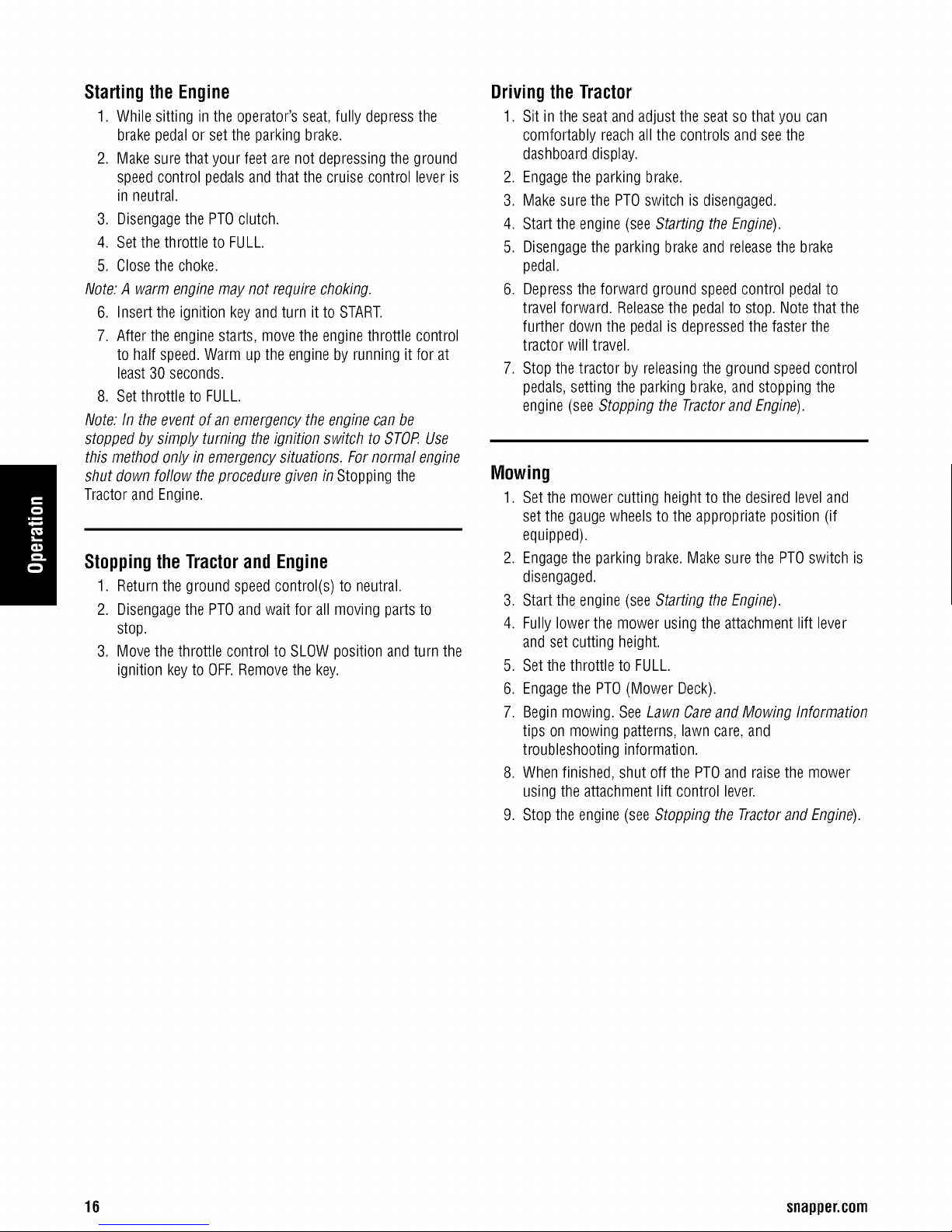
Starting the Engine
1. While sitting in the operator's seat,fully depress the
brake pedalor set the parking brake.
2. Make sure that your feet arenot depressingthe ground
speedcontrol pedalsand that the cruise control lever is
in neutral.
3. Disengagethe PTOclutch.
4. Setthe throttle to FULL.
5. Closethe choke.
Note:A warm engine maynot require choking.
6. Insert the ignition key andturn it to START.
7. After the enginestarts, move the engine throttle control
to half speed.Warm up the engine by running it for at
least 30 seconds.
8. Setthrottle to FULL.
Note: In theevent of an emergency the engine canbe
stopped by simply turning the ignition switch to STOP.Use
this method only in emergency situations. For normal engine
Tractorand Engine.
Stoppingthe Tractorand Engine
shut down follow theprocedure given inStopping the
1. Return the ground speedcontrol(s) to neutral.
2. Disengagethe PTOand wait for all moving parts to
stop.
3. Move the throttle control to SLOW position andturn the
ignition keyto OFF.Removethe key.
Driving the Tractor
1. Sit in the seat andadjust the seat so thatyou can
comfortably reachall the controls and see the
dashboarddisplay.
2. Engagethe parking brake.
3. Make surethe PTOswitch is disengaged.
4. Start the engine (seeStarting the Engine).
5. Disengagethe parking brakeand releasethe brake
pedal.
6. Depress the forward ground speedcontrol pedal to
travel forward. Releasethe pedalto stop. Notethat the
further down the pedalis depressedthe faster the
tractor will travel.
7. Stop the tractor by releasingthe ground speedcontrol
pedals, setting the parking brake,and stopping the
engine (see Stopping the Tractorand Engine).
Mowing
1. Set the mower cutting height to the desired leveland
set the gauge wheelsto the appropriate position (if
equipped).
2. Engagethe parking brake. Make surethe PTOswitch is
disengaged.
3. Start the engine (seeStarting the Engine).
4. Fully lower the mower using the attachment lift lever
and set cutting height.
5. Set the throttle to FULL.
6. Engagethe PTO(Mower Deck).
7. Begin mowing. SeeLawn Careand Mowing Information
tips on mowing patterns,lawn care,and
troubleshooting information.
8. When finished, shut off the PTOand raise the mower
using the attachment lift control lever.
9. Stop the engine (see Stopping the Tractorand Engine).
16 snapper.corn
Page 19
WARNING
The enginewill shutoffif the reversegroundspeed
pedalis depressedwhile the PTOis onandthe RMO
hasnotbeenactivated. The operatorshouldalways
turnthe PTOoffpriortodrivingacrosson roads,
pathsorany area thatmaybeusedbyothervehicles.
Suddenlossofdrivecouldcreatea hazard.
WARNING
Mowingin reversecan be hazardousto bystanders.
Tragicaccidentscanoccurif the operatoris notalert
tothe presenceof children.NeveractivateRMO if
childrenare present.Childrenare oftenattractedto
theunitand themowingactivity.
Mowingin Reverse
If an operator chooses to mow in reverse,the RMO system
can beused. Tousethe ReverseMowing Option (RMO) turn
the RMOkey afterthe PTOis engaged.The LED. light will
illuminate, andthe operator canthen mow in reverse.Each
time the PTOis engagedthe RMO needsto be reactivatedif
desired. The keyshould be removed to restrict accessto the
RMO feature.
AttachmentOperationin Reverse
If an operator chooses to operate a PTOdriven attachmentin
reverse,the RMOsystem can be used. Touse the Reverse
Mowing Option (RMO)turn the RMO keyafter the PTOis
engaged.The L.ED. light will illuminate, andthe operator
canthen operatethe attachment in reverse.Eachtime the
PTOis disengagedthe RMOneedsto bereactivated if
desired. The keyshould be removed to restrict accessto the
RMO feature.
LawnCareand MowingInformation
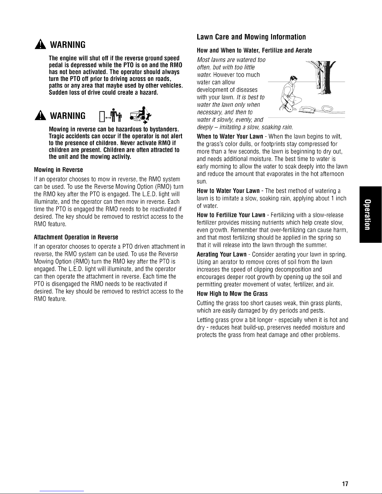
Howand When to Water, Fertilizeand Aerate
Most lawnsare watered too
often, but with too little
water.Howevertoo much
water can allow
developmentof diseases
with your lawn. It is best to
water the lawn only when
necessary,and then to
water it slowly, evenly,and
deeply- imitating a slow, soaking rain.
WhentoWater YourLawn- When the lawn beginsto wilt,
the grass'scolor dulls, or footprints stay compressed for
more than afew seconds, the lawn is beginning to dry out,
and needs additional moisture. The best time to water is
early morning to allow the water to soak deeply into the lawn
and reducethe amountthat evaporates in the hot afternoon
sun.
Howto Water YourLawn -The best method of watering a
lawn is to imitate a slow, soaking rain,applying about 1inch
of water.
Howto Fertilize YourLawn - Fertilizingwith a slow-release
fertilizer providesmissing nutrients which help create slow,
evengrowth. Rememberthat over-fertilizing can causeharm,
and that most fertilizing should be appliedin the spring so
that it will releaseinto the lawn through the summer.
AeratingYourLawn - Consider aeratingyour lawn in spring.
Using an aeratorto remove cores of soil from the lawn
increasesthe speedof clipping decomposition and
encouragesdeeper root growth by opening upthe soil and
permitting greater movement of water,fertilizer, and air.
How Highto Mow theGrass
Cutting the grasstoo short causesweak,thin grass plants,
which are easilydamagedby dry periods and pests.
Letting grass grow a bit longer - especiallywhen it is hot and
dry - reduces heat build-up, preservesneeded moisture and
protects the grass from heatdamageand other problems.
17
Page 20
Cuttingofftoomuchatonetimeshockstheplant'sgrowth
systemandweakensthegrassplants.A good rule of thumb
is the 1/3 rule: to cut no more than one third of thegrass
height, and never more than 1inch at atime.
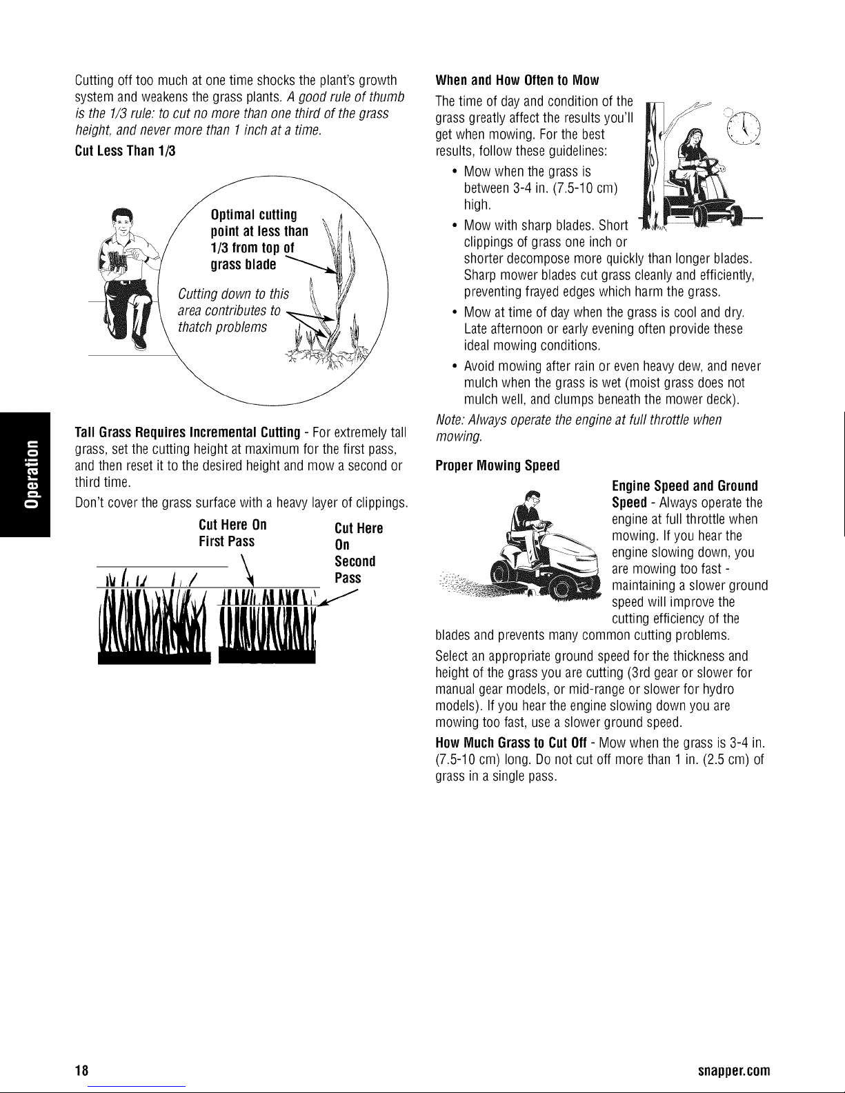
CutLessThan1/3
Optimalcutting
point at lessthan
1/3 fromtop of
grassblade
Cutting down to this
area contributes to
thatch problems
Tall GrassRequiresIncrementalCutting- Forextremelytall
grass, setthe cutting height at maximum for the first pass,
and then reset it to the desiredheight and mow asecond or
third time.
Don't cover the grass surfacewith a heavylayerof clippings.
CutHere On CutHere
FirstPass On
I_ if, IJ Is/ Pass
Second
Whenand How Oftento Mow
Thetime of dayand condition of the
grass greatly affectthe resultsyou'll
get when mowing. For the best
results, follow theseguidelines:
• Mow when the grass is
between 3-4 in. (7.5-10 cm)
high.
• Mow with sharp blades.Short
clippings of grass one inch or
shorter decompose more quickly than longer blades.
Sharp mower bladescut grass cleanlyand efficiently,
preventing frayed edgeswhich harmthe grass.
• Mow at time of day when the grass is cool and dry.
Lateafternoon or early evening often providethese
ideal mowing conditions.
• Avoid mowing after rainor even heavydew, and never
mulch when the grass is wet (moist grass does not
mulch well, andclumps beneaththe mowerdeck).
Note:Always operatetheengine at furlthrottle when
mowing.
ProperMowingSpeed
EngineSpeedand Ground
Speed- Always operate the
engine at full throttle when
mowing. If you hearthe
engine slowing down, you
are mowing too fast -
maintaining a slower ground
speedwill improve the
cutting efficiency of the
bladesand preventsmany common cutting problems.
Select an appropriate ground speedfor the thickness and
height of the grass you arecutting (3rd gearor slower for
manual gearmodels, or mid-range or slower for hydro
models). Ifyou hearthe engine slowing down you are
mowing too fast, usea slower ground speed.
How MuchGrassto Cut Off- Mow when the grass is 3-4 in.
(7.5-10 cm) long.Do not cut off more than 1 in.(2.5 cm) of
grass in a single pass.
18 snapper.corn
Page 21
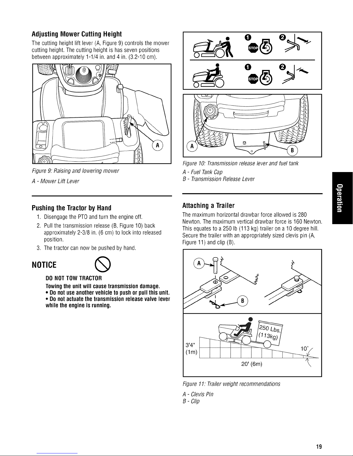
Adjusting Mower Cutting Height
Thecutting height lift lever (A, Figure9) controls the mower
cutting height.The cutting height is hasseven positions
betweenapproximately 1-1/4 in. and 4 in. 3.2-10 cm).
Figure 9: Raisingand lowering mower
A - Mower Lift Lever
\
JJJ, 7/
Figure 10. Transmissionreleaselever and fuel tank
A - FuelTankCap
B - TransmissionReleaseLever
Pushing the Tractor by Hand
1. Disengagethe PTOand turn the engine off.
2. Pull the transmission release(B, Figure10) back
approximately 2-3/8 in. (6 cm) to lock into released
position.
3. The tractor can now bepushed by hand.
NOTICE Q
DO NOTTOW TRACTOR
Towingthe unitwill causetransmissiondamage.
• Do notuse anothervehicle to pushor pull this unit.
• Do notactuatethe transmissionrelease valve lever
whilethe engineis running.
Attachinga Trailer
Themaximum horizontal drawbar force allowed is 280
Newton. The maximum vertical drawbar force is 160 Newton.
This equatesto a 250 Ib (113 kg) trailer on a 10 degree hill.
Securethe trailer with an appropriately sizedclevis pin (A,
Figure11) and clip (B).
I
1411
(lm)
J
®
10°
20' (6m)
Figure 11. Trailerweight recommendations
A - ClevisPin
B- Clip
19
Page 22

MaintenanceRecords
20 snapper.com
Page 23
Maintenance
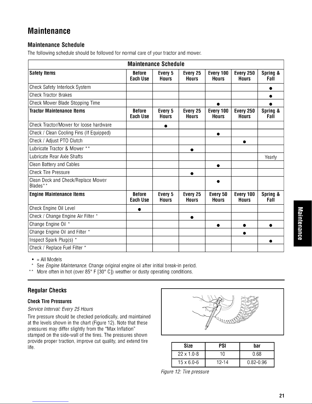
MaintenanceSchedule
Thefollowing schedule should be followed for normal careof your tractor andmower.
MaintenanceSchedule
SafetyItems Before Every5 Every25 Every100 Every250 Spring&
EachUse Hours Hours Hours Hours Fall
CheckSafety Interlock System •
CheckTractor Brakes •
CheckMower BladeStopping Time • •
TractorMaintenanceItems Before Every5 Every25 Every100 Every250 Spring&
CheckTractor/Mower for loose hardware •
Check/ CleanCooling Fins (If Equipped) •
Check/ Adjust PTOClutch •
Lubricate Tractor & Mower ** •
Lubricate Rear AxleShafts Yearly
CleanBattery and Cables •
CheckTire Pressure •
CleanDeck and Check/ReplaceMower •
Blades**
EachUse Hours Hours Hours Hours Fall
EngineMaintenanceItems Before Every5 Every25 Every50 Every100 Spring&
EachUse Hours Hours Hours Hours Fall
CheckEngine OilLevel •
Check/ ChangeEngineAir Filter * •
ChangeEngineOil * • • •
ChangeEngineOil and Filter * •
Inspect Spark Plug(s) * •
Check/ ReplaceFuelFilter *
• = All Models
* See EngineMaintenance.Changeoriginal engineoil after initial break-in period.
** More often in hot (over 85° F[30° C]) weather or dusty operating conditions.
Regular Checks
CheckTire Pressures
Service Intervah Every25 Hours
Tire pressureshould be checked periodically, and maintained
at the levelsshown in the chart (Figure12). Notethat these
pressures maydiffer slightly from the "Max Inflation"
stamped onthe side-wall of the tires. The pressuresshown
provide propertraction, improve cut quality, andextend tire
life.
Size
22 x 1.0-8
15 x 6.0-6
PSI bar
10 0.68
12-14 0.82-0.96
Figure 12: Tirepressure
21
Page 24
Safety InterlockSystemCheck
Service Interval: EveryFail and Spring
Checkthe function of the safety interlock system using the
test procedurefound inthe Operationsection of this manual.
If the tractor fails any of the tests, seeyour dealer.
BladeBrakeCheck
Service Interval: Every 100Hours or Failand Spring
Mower bladesand mowerdrive belt should come to a
complete stop within five seconds after the electric PTO
switch isturned off.
1. With tractor in neutral, PTOdisengagedand operator in
seat,start the engine.
2. Look over the left-hand footrest at the mower drive
belt. Engagethe PTOand wait severalseconds.
Disengagethe PTOand check the amount of time it
takesfor the mower drive belt to stop.
3. If mower drive belt doesnot stop within five seconds,
re-adjust the clutch or see your dealer.
PTOClutchAdjustmentCheck
Service Intervah Every250 Hrs.
Checkthe PTOclutch adjustment after every250 hours of
operation - or if the clutch startsslipping or will not engage.
Checkand adjust the clutch using the procedureoutlined in
the Troubleshooting,Adjustment, and Servicesection of this
manual.
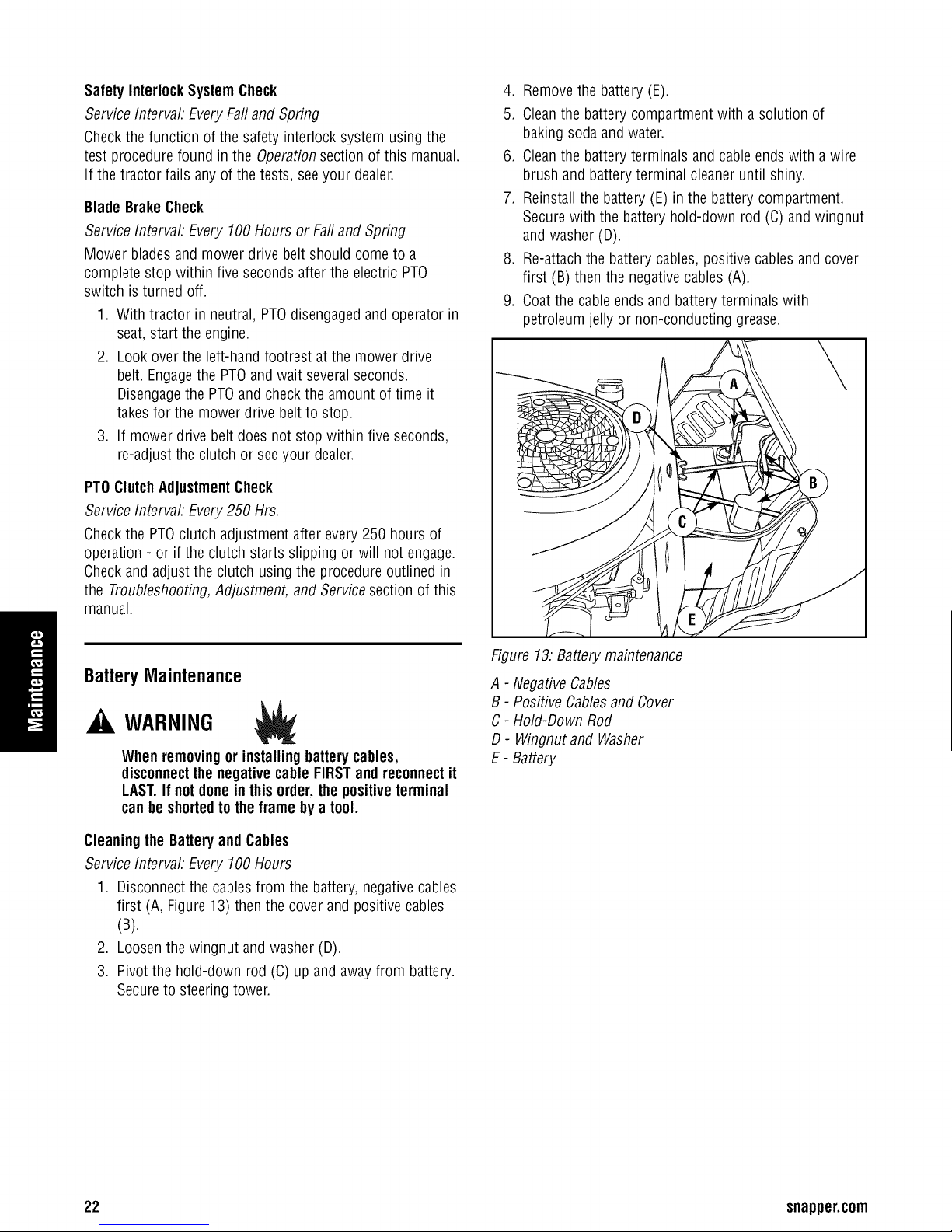
4. Removethe battery (E).
5. Cleanthe battery compartment with a solution of
baking sodaand water.
6. Cleanthe batteryterminals and cable ends with awire
brush and batteryterminal cleaneruntil shiny.
7. Reinstall the battery (E) in the battery compartment.
Securewith the battery hold-down rod (C)and wingnut
and washer (D).
8. Re-attachthe battery cables, positive cables andcover
first (B) then the negativecables (A).
9. Coatthe cableendsand battery terminals with
petroleum jelly or non-conducting grease.
BatteryMaintenance
WARNING
Whenremovingor installingbatterycables,
disconnectthe negative cable FIRSTand reconnectit
LAST.If notdonein this order,the positiveterminal
canheshortedto the frame by a tool.
Cleaningthe Batteryand Cables
Service Intervah Every 100Hours
1. Disconnect the cablesfrom the battery, negativecables
first (A, Figure 13) then the cover and positivecables
(B).
2. Loosenthe wingnut and washer (D).
3. Pivot the hold-down rod (C) up and awayfrom battery.
Secureto steering tower.
Figure 13:Batterymaintenance
A - NegativeCables
B - Positive Cablesand Cover
C- Hold-Down Rod
D- Wingnut and Washer
E- Battery
22 snapper.com
Page 25
TransmissionMaintenance
TransmissionIdentification
Todetermine what transmission is in your tractor, checkthe
identification tag attachedto the axleof the transmission
(Figure 14), or checkyour tractor's parts book.
K46Maintenance
The K46is a sealed unit and does not require regular
maintenance. If the transmission lacks drive or is excessively
noisy, it mayneedto bepurged. Seeyour Dealer.
Figure 14: TransmissionID tag location
Figure 15.Headlight
A - Socketand Bulb
B - Bezel
A - ID Tag
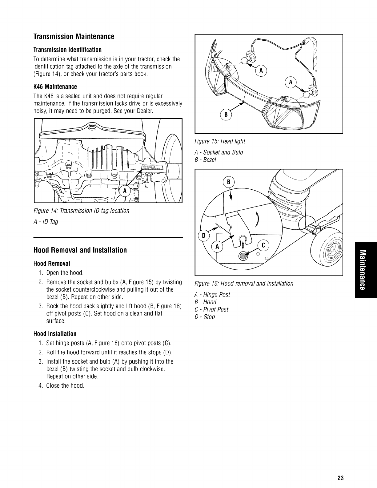
Hood Removal and Installation
HoodRemoval
1. Openthe hood.
2. Removethe socketand bulbs (A, Figure15) by twisting
the socketcounterclockwise and pulling it out of the
bezel(B). Repeaton other side.
3. Rockthe hood backslightly and lift hood (B, Figure16)
off pivot posts (C). Set hood ona clean and flat
surface.
HoodInstallation
1. Set hinge posts (A, Figure16) onto pivot posts (C).
2. Roll the hood forward until it reachesthe stops (D).
3. Install the socketand bulb (A) by pushing it into the
bezel(B) twisting the socket andbulb clockwise.
Repeaton other side.
4. Closethe hood.
Figure 16.Hood removal and installation
A - HingePost
B - Hood
C- Pivot Post
D- Stop
23
Page 26
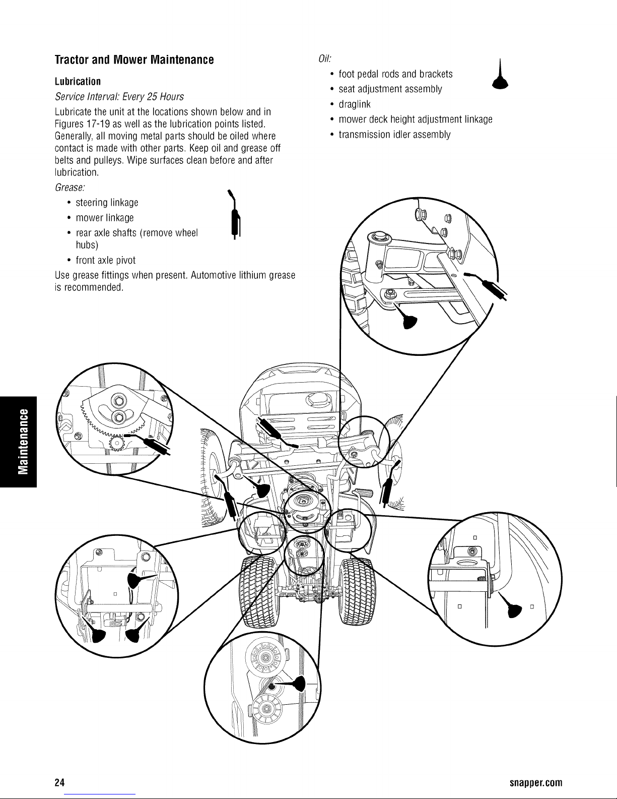
Tractorand MowerMaintenance
Lubrication
Service Intervah Every25 Hours
Lubricate the unit at the locations shown below and in
Figures 17-19 aswell asthe lubrication points listed
Generally,all moving metal partsshould beoiled where
contact is madewith other parts Keepoil andgreaseoff
belts and pulleys Wipe surfaces clean before and after
lubrication
Grease:
• steering linkage
• mower linkage
• rearaxle shafts (remove wheel
hubs)
• front axle pivot
Use greasefittings when present Automotive lithium grease
is recommended
Oil:
• foot pedal rods andbrackets ,_
• seat adjustment assembly
• draglink
• mower deckheight adjustment linkage
• transmission idler assembly
1
Q
24 snapper.com
D
Page 27

/
/
/
Figure 18:Lubricate decklinkage (38 in. shown)
Figure 17.Arbor lubrication points
LubricateRear Axle Shafts
Service Interval: Yearly
We recommend removingthe rearwheel hubs and
lubricating the axle shafts yearly. This preventsthe wheel
hubs from seizing onto the axleshaft andmakesfuture
service easier.
1. Turn off the ignition, turn off the PTO,engagethe
parking brake,and block the front tires.
2. Using ajack or chain hoist positioned atthe center of
the rearframe, carefully jack the unit up until the rear
tires are approximately1-2 in. (2.5-5 cm) off the
ground.
Note: For overallunit stability during service, donot jack rear
end higher than required for wheel removal
3. Support the rearof the unit onjackstands positioned
under the rearframe.
Note: Youraxle assembly may differ slightly from the
assembly pictured: the quantity of washers is adjusted to
allow a smaflamount of axleend-play.
4. Removethe hardware retaining the wheel assembly to
the axleand lubricatethe axleshaft using anti-seize
compound or lithium grease.
5. Reinstallthe components in reverseorder of
disassemblyand lower the unit. Besure the key (A,
Figure19) is in placein the axle keyway.
"
Figure 19:Rearaxle hardware
A - Key
B- Spacer
C - Wheeland Hub
D- Special Washer
E- Small Washer
F- E-Clip
G- Axle Cap
H- Large Washer
25
Page 28

: 3d
WARNING
Foryourpersonalsafety,do not handlethe sharp
mowerbladeswith barehands. Carelessor improper
handlingof blades may resultinseriousinjury.
WARNING
Foryour personalsafety,blade mountingcapscrews
musteachbe installedwithtwo springwashersora
hexwasherand springwasher,then securely
tightened.Torqueblade mountingnutto 70-80 ft-lb
(95-108 Nm). Torqueblademountingcapscrewto 45-
55 ft-lb (61-75 Nm).
Servicingthe Mower Blades
Service Intervah Every 100Hours orAs Required
1. Remove mower deck(see Mower DeckRemovaland
Installation in the Assembly section).
2. SeeFigure21. To remove bladefor sharpening, usea
block of wood to prevent blade rotation while loosening
the capscrew.
3. Rremovethe capscrew (D, Figure22), hexwasher (B),
spring washer (C), and blade.
4. Use a file to sharpen bladeto a fine edge. If bladeis
damaged, it must be replaced.
5. Balancethe bladeas shown in Figure20. Centerthe
blade'shole on anail lubricated with a drop of oil. A
balancedbladewill remain level.
.
Reinstallthe blade(Figures22) with thetabs pointing
up toward the mower deckasshown.
7.
Reinstallthe hexwasher (B, Figure 22), spring washer
(C) andcapscew (D). Use awooden block (A) to
prevent blade rotationwhile tightening the nut (D) to
45-55 ft-lb (61-75 Nm).
Figure20: Balancingthe blade
A - Workbench
B - Nail
Figure21: Bladeremoval - follow arrow to loosen
26 snapper.com
Figure22: Bladeinstallation
A - 4x4 WoodBlock
B - HexWasher
C- Spring Washer
D- Blade Capscrew
Page 29

EngineMaintenance
Checkand Fill EngineOil
Service Interval. BeforeEachUse,and Every 8 Hours
1. Turn the engine off, and set the parking braketo PARK.
2. Cleanthe areaaround the dip stick (C,Figure23).
3. Removethe dip stick (C) and clean it with a paper
towel.
4. Insert the dip stick (C) back into the engine. Threadthe
cap backonto the tube.
5. Removethe dip stick and readthe oil level.Theoil level
should bebetweenthe FULLand ADDmarks (D). If not,
add oil according to the oil recommendations chart
(Figure 23).
Figure23: Briggs & Stratton two cylinder models
A - OilDrain Valve
B - OilFilter
C - Dip Stick
D -CheckingOil Level
27
Page 30

Oil DrainValve Operation
1. Place a suitable container with a4 quart capacity under
the oil drain valve (A, Figure23 or 24).
2. Loosen or removethe dip stick (C,Figure23).
3. Wipe oil drain valve (B, Figure24) and cover (C)with
paper towel or rag.
Note: Sliding a hose with a 1/2 in. (12.5 ram) inside diameter
tube over the valvenipple may aidin guiding the draining oil.
4. Rotatethe drain valve (B) counter clockwise and pull
out 1/4 in. (6.35 mm) for engineoil to drain. Allow
ampletime for complete drainage.
5. After all the oil hasdrained, close the oil drain valve (B)
by pushing in androtating clockwise to close.
6. Wipethe nipple (D) with paper towel or rag. Install the
cover (C)over nipple (D).
ChangeEngineOil
Service Intervah 50 Hours or Onceper Season
Oil Capacity: Approximately 1-7/8 quarts (1.8 L) without filter
change.
Note: Changeengine oil whilethe engine is warm. Run the
engine for a few minutes, then shut the engine off and allow
it to cool from hot to warm.
1. Cleanthe area around the dip stick (C, Figure23) and
oil drain valve(A).
2. Drain engine oil. See OilDrain ValveOperationabove.
Figure24: Oildrain valve -closed (left view), open (right
view)
A - EngineBlock/Valve Base
B - OilDrain Valve
C- Cover
D- Nipple
Useoil classifiedAPI Service ClassSF,
SG,SH,SJ or better withSAEViscosity:
I r
NN
Change EngineOil and Filter
Service Interval: 100 Hours or Onceper Season
3. Fillthe crankcasewith oil. See CheckEngine Oil Level
Oil Capacity: Approximately 2 quarts (1.9 L) with oil filter
change.
Note. Changeengine oil whilethe engine is warm. Run the
engine for a few minutes, then shut the engine off and allow
it to cool from hot to warm.
1. Cleanthe area around the dip stick (C, Figure23) and
oil drain valve(A).
2. Drain engine oil. See OilDrain ValveOperationabove.
3. Removethe oil filter (B). Discardthefilter.
4. Using a drop of oil on your finger tip, wet the rubber
gasketon the bottom of the new filter.
°F -20 0 20 32 40 60 80 100
°C -30 -18 -7 O 4 16 27 38
*CAUTION:Air cooled engines run hotter than automotive engines.
The use of non-synthetic multi-viscosity oils (5W-30, 1OW-3O,etc,)
in temperatures above 400F (4°C)will result inhigher than normal
oil consumption. When using a multi-viscosity oil, check oil level
more frequently.
**CAUTION: SAE30 oil, if used below 40oF(4°C),will result in hard
starting and possibleengine bore damagedue to inadequate
lubrication.
Figure25. Recommendedengine oil - Briggs & Stratton
models
5. Turn the filter clockwise until the rubber gasketmeets
the filter base.Thenturn 1/2 to 3/4 turn more.
6. Fill the crankcasewith oil. See CheckEngine Oil Level
7. Test run the engineto checkfor leaks.Stopthe engine
for 1 minute, then recheckthe oil level.
28 snapper.com
Page 31

Air Filter and Pre-Cleaner Service
Service Intervah Every25 hours or as required.
1. Loosen the air filter cover screws (A, Figure 26) and
removethe air filter cover.
2. Locatethe air filter cartridge (A, Figure 27). Pull up on
the front edgeof the cartridge until it snaps out of
place.
3. Inspect the cartridge for dirt or damage.
If the thin foam sleevesurrounding the filter is
damaged, replacethe filer. DONOToil the foam sleave
or cartridge. If there is oil of heavy dirt onthe
cartridge, replaceit.
DONOTusepressurized air or solvents to cleanthe
filter cartridge.
Removeany dirt from the air filter housing.
4. Replacethe cartridge by aligning the hole of the
cartridge with the air vent (A, Figure28).
5. Pushthe cartridge in toward the engine until it snaps
into place.
6. Reinstallthe air filter cover andtighten the screws (A,
Figure26).
Figure27. Air Filter Removal
A - FilterCartridge
Figure26. Air Filter Cover
A - Air FilterCover Screws
Figure28. Air Filter Installation
A - FilterCartridge
29
Page 32

ReplaceSpark Plug
Service Intervah Yearly
Spark PlugGap:.030 in. (.76 mm)
ReplacementSpark Plug: ResistorSpark Plug,Champion
RC12YC
1. Stop the engine andallow it to cool.
2. SeeFigures 29. Cleanthe area around the spark plug.
3. Removethe spark plug.
4. Checkthe sparkplug gap. It should be .030 in. (see
Figure29).
5. Reinstallthe plug into the cylinder head.Torquethe
plug to 180 in-lb (20 Nm).
=
030'
Storage
Beforeyou store your unit for the off-season, readthe
WARNING
Neverstorethe unit(withfuel) inan enclosed,poorly
ventilatedstructure.Fuelvaporscantravel to an
ignitionsource(suchas a furnace,water heater,etc.)
and causean explosion.
Fuelvaporis also toxictohumansandanimals.
Maintenanceand Storage rulesand information in the
OperatorSafety section, then perform the following steps:
• Disengagethe PTO,set the parking brake,and remove
the key.
• Perform enginemaintenanceand storage measures
listed in the engine owner's manual. This includes
draining the fuel system, or addingstabilizerto the fuel
(do not store a fueled unit in anenclosed structure -
seewarning).
• Battery life will be increasedif it is removed, put in a
cool, dry placeand fully charged about once a month.
If the battery is left in the unit, disconnectthe negative
cable.
Beforestarting the unit after it has beenstored:
• Check all fluid levels. Checkall maintenance items.
• Perform all recommendedchecks and procedures
found the Operationsection.
• Allow the engine to warm up for several minutes before
use.
Figure29: Sparkplug gapping
30 snapper.com
Page 33

Troubleshooting,
Adjustment,andService
Troubleshooting
While normal care and regular maintenancewill extendthe
life of your equipment, prolonged or constant use may
eventually requirethat service be performed to allow it to
continue operating properly.
Thetroubleshooting guide below lists the most common
problems, their causes,and remedies.
Seethe information on the following pagesfor instructions
on how to perform most of these minor adjustmentsand
service repairsyourself. If you prefer, all of theseprocedures
can beperformed for you by your local authorized dealer.
TroubleshootingtheTractor
Problem Cause Remedy
Enginewill not 1. Brakepedal not depressed. Fullydepress brake pedal.
turnover.
2. Ignition switch not turned fully to START Turn ignition switch fully to STARTposition.
position.
WARNING
Toavoidseriousinjury, performmaintenanceonthe
tractoror moweronlywhentheengine is stoppedand
theparkingbrakeengaged.
Alwaysremovethe ignitionkey, disconnectthespark
plugwire and fastenitaway fromthe plugbefore
beginningthemaintenance,to preventaccidental
startingof theengine.
3. PTO(electric clutch) switch in ONposition. Placein OFFposition.
4. Cruisecontrol engaged. Move knob to Neutral/Offposition.
5. Batteryterminals require cleaning. Cleanthe battery terminals.
6. Baterydischarged or dead Rechargethe battery (follow the battery charger
manufacture'sinstructions andsafety messages).
7. Wiring loose or broken. Visuallycheck wiring and replacebroken orfrayed
wires. Tightenlooseconnections.
8. Fuseblown. Replacefuse.
9. Safetyinterlock switch faulty. Replace.Contactyour local authorized dealer.
10. Solenoidor starter motor faulty. Replace.Contactyour local authorized dealer.
Enginewill not 1. Engineis cold; choke not in CLOSEDposition. Movechoke to CLOSEDposition.
start.
2. Engineis warm; choke not in OPENposition. Move choketo OPENposition.
3. Engineflooded. Set choketo OPENposition when cranking engine.
4. Outof fuel. Allow it to cool,then refill the fueltank.
5. Fuelis old or stale,or water in fuel. Drainfuel and refill with fresh fuel. Note:Fuel related
issuesare not covered under warranty.
Engine runs 1. Chokecontrol not opened after enginestarts. After the engine starts, set the chokecontrol to OPEN
poorly, position.
Engineknocks. 1. Low oil level. Check/addoil as required.
2. Usingwrong gradeoil. See "ChangeEngineOil" in the MaintenanceSection.
3. Fuelis old or stale,or water in fuel. Drainfuel and refill with fresh fuel. Note:Fuel related
issuesare not covered under warranty.
31
Page 34

Troubleshootingthe Tractor(Continued)
Problem Cause
Excessiveoil consumption. 1. Engine running too hot.
2. Too much oil in crankcase.
3. Using wrong weight oil.
Engineexhaustis black.
Engineruns,but tractorwill not
drive.
.
Chokeset to CLOSEwhen engine
is running.
.
oo much oil in crank case.
1.
Parking brakeis engaged.
2.
Ground speed control pedals not
depressed.
Transmission releaselever in
3.
"push" position.
.
Drive belt slips.
Drive belt is broken
5.
Remedy
Cleanengine fins, blower screen andair
cleaner.Cleanradiator screen.
Checkthe oil level, drainexcess oil as
required.
See"Change EngineOil" in the
MaintenanceSection of operator's manual
for complete oil specifications.
Setchoke to OPENas soon as engine
starts.
Checkthe oil level, drainexcess oil as
required.
Disengageparking brake.
Depress3edals.
Stop engmeand move into drive
position.Seeyour Dealer.
Seecause and remedy below.
Seeyour Dealer
Tractordrivebelt slips.
Brakewill nothold.
Tractorsteershardor handles
poorly.
1.
Pulleys or belt greasy or oily.
Belt stretchedor worn.
2.
3.
Idler pulley pivot bracket "frozen"
in declutched position.
Internal brakeworn.
1. Seeyour dealer.
1.
Improper tire inflation
Cleanas required.
Seeyour Dealer.
Removeidler pulley bracket, cleanand
lubricate.
Checkand correct.Checkandtighten any
loose connections. SeeSteeringGear
Adjustment.
2. Front wheel spindle bearingsdry.
GearAdjustment.Greasespindles. See
Tractorand Mower Maintenancein the
Maintenancesection.
3. Steering linkage is loose.
Checkand correct.Checkandtighten any
loose connections.
32 snapper.com
Page 35

Troubleshootingthe Mower
Problem Remedy
Mower will not raise. 1. Attachor repair.
Mower cut is uneven.
Mower cut is rough looking.
Enginestalls easilywith mower
engaged.
Excessivemower vibration.
Lift linkagenot properly attached
or damaged.
,
Mower not leveledproperly.
2.
Tractortires not inflated equally or
properly.
.
Engine speedtoo slow.
2.
Ground speed too fast.
Bladesare dull.
3.
.
Mower drive belt slipping because
it is oily or worn.
5.
CheckPTO(Electric Clutch)
Adjustment.
6.
Bladesnot properly fastened to
arbors.
1.
Engine speedtoo slow.
2.
Ground speed too fast.
3.
Dirty or cloggedair filter.
4.
Cutting height settoo low.
5.
Dischargechute jamming with cut
grass.
6.
Engine not up to operating
temperature.
7.
Starting mower intall grass.
1.
Blade mounting screws are loose.
2.
Mower blades, arbors,or pulleys
are bent.
3.
Mower bladesare out of balance.
Cause
See Leveling the Mower in this section.
See Regular Checksin the Maintenance
section.
Setto full throttle.
Slow down.
Sharpen or replaceblades.See Tractorand
Mower Maintenancein the Maintenance
section.
Cleanor replace belt as necessary.
SeeAdjustments section.
See Tractor and Mower Maintenancein the
Maintenancesection.
Setto full throttle.
Slow down.
SeeEngine Maintenancein the
Maintenancesection.
Cut tall grass at maximum cutting height
during first pass.
Cut grass with discharge pointing toward
previously cut area.
Runenginefor severalminutes to warm-
up.
Start the mower in aclearedarea.
Tighten to 45-55 ft-lb (61-75 Nm).
Checkand replaceas necessary.
Remove,sharpen,and balanceblades. See
Tractorand Mower Maintenancein the
Maintenancesection.
Excessivebelt wear or breakage.
Mower drive belt slips or fails to
drive.
4. Belt installed incorrectly.
1. Bent or rough pulleys.
2. Using incorrect belt.
1. Idler pulley spring brokenor not
properly attached.
2. Belt stops out of adjustment.
3. Mower drive belt broken.
4. PTOclutch out of adjustment.
Reinstallcorrectly.
Repairor replace.
Replacewith correct belt.
Repairor replaceas needed.
Checkbelt stops.
Replacedrive belt.
Adjust PTOclutch.
33
Page 36

Adjustments
PTOClutchAdjustment
Seat Adjustment
Theseat can be adjustedforward and back.Move the lever
(A, Figure30), position the seat as desired,and releasethe
leverto lock the seatinto position.
Figure30: Seatadjustment
A - SeatAdjustment Lever
BatteryCharging
WARNING
Keepopenflames andsparksaway fromthe battery;
thegassescomingfrom it are highlyexplosive.
Ventilatethe batterywell duringcharging.
A dead battery or one too weakto start the engine may be
the result of a defect in the charging system or other
electrical component. If there is anydoubt about the cause
of the problem, seeyour dealer.If you needto replacethe
battery, follow the steps under Battery Maintenance in the
Maintenancesection.
Tochargethe battery,follow the instructions provided bythe
battery charger manufactureras well as allwarnings
included in the safety rules sections of this book. Chargethe
battery until fully charged.Donot chargeat a rate higher
than 10 amps.
WARNING
Toavoidseriousinjury, performadjustmentsonly
with enginestopped,keyremovedandtractor on
level ground.
Checkthe PTOclutch adjustment after every250 hours of
operation. Also perform the following procedure if the clutch
is slipping or will not engage,or if a newclutch has been
installed.
1. Remove key from ignition switch and disconnect spark
plug wires to prevent the possibility of accidental
starting while the PTOis beingadjusted.
2. See Figure31. Notethe position of the 3adjustment
windows (A) in the sideof the brake plateand the
nylock adjustment nuts (B).
3. Insert a .012 in.-.015 in. (2,5-4 mm) feeler gauge(C)
through eachwindow, positioning the gauge between
the rotor faceandthe armature face as shown in
Figure32.
4. Alternatelytighten the adjustment nuts (B, Figure31)
until the rotor face andarmature face just contactsthe
gauge.
5. Checkthe windows for an equal amount of tension
when the gaugeis inserted and removed,and makeany
necessaryadjustments bytightening or loosening the
adjustment nuts.
Note: Theactual air gapbetween the rotor and armature may
vary even after performing the adjustmentprocedure. Thisis
due to dimensional variations on component parts, and is an
acceptablecondition.
6. Checkthe mower bladestopping time. The mower
bladesand mower drive belt should come to a
complete stop within five seconds after the electric PTO
switch isturned off.
7. Perform the BladeBrakeCheckfound in the
Maintenancesection. Mower bladesand mower drive
belt should cometo a completestop within five
seconds afterelectric PTOswitch is turned off.
BrakeAdjustment
This unit does not havea manually adjustablebrake. If brake
does not function properly seeyour dealer.
34 snapper.com
Page 37

Figure31: PTOclutch adjustment
A - Adjustment Window (Qty.3, one shown)
B - Adjustment Nut
MowerAdjustments- GaugeWheels
Themower gauge wheelscan be placedin two positions
depending on the height of cut. When using highercutting
heights, setthe wheels in the lower position. When using
lower cutting heights, set the wheels in the upper position.
Donot allow wheelsto remainon the ground constantly
while mowing. To adjust:
1. Remove the Iocknut (B, Figure 33), gauge wheel (C),
washers (D), and shoulder bolt (E). Changeposition of
gaugewheel to desired height.
2. Insert shoulder bolt (E)through washers (D) gauge
wheel (C),and gaugewheel bracket(A). Secure with
Iocknut (B). Repeatsteps 1 and 2 for all gaugewheels.
Figure32: Adjust PTOclutch
A - Window
B - Adjustment Nut
C - FeelerGauge
Figure33: Fixedbracket gauge wheeladjustment
A - GaugeWheel Bracket
B - Locknut
C- GaugeWheel
D- Washer
E - Shoulder Bolt
35
Page 38

Service LevelingtheMower
FuseReplacement
Thefuse is a 20-amp bladetype automotivefuse located
behind the batteryon the steering tower. Replaceonly with
the sameratedfuse, 20-amp.
Toreplacethe fuse:
1. Openthe hoodand locate the fuse holder (B, Figure34)
and fuse (A). Attached to the steeringtower.
2. Hold the fuse holder (B) and pull outthe fuse (A).
3. Inspect the fuse for a broken fusible link. SeeFigure 35.
Replacefuse if connection is broken. If you are not
sure if the fusible link is broken replacefuse.
4. Hold the fuse holder (B, Figure34) and insert newfuse
(A) until it is seated properly.
Figure34. Fuse
A - Fuse,20-amp
B - FuseHolder
Cm m
m
m
i i
I
t i
Figure35. Bladetype fuse
A - Goodfuse with solid fusible link
B - Blown fuse with broken fusiblelink
mm
mm
JL
mm
WARNING
Beforecheckingmower,shutoff PTOand engine,
removethekey,and allow all movingpartstostop.
If the cut is uneven,the mower may needleveling. Unequal
or improper tire pressuremay also causean unevencut.
Make sure tire pressure is correct as specified in Checking
TirePressure in the Maintenancesection.
Side-to-SideLeveling
1. With the mower installed, placethe tractor on a
smooth, levelsurface suchas a concretefloor. Turn the
front wheels straight forward.
2. Checkfor bent bladesand replace if necessary.
3. Placethe mower in mid-cut position. Arrangethe
outside mower bladesso that they arepointing from
side-to-side.
4. Measurethe distancebetweenthe outsidetips of each
blade and the ground. If there is more than 1/8 in.
(3 mm) difference betweenthe measurementson each
side, proceedto step 5. If the difference is 1/8 in.
(3 mm) or less, proceed to step 6.
5. Turn the Iocknut (B, Figure 36) to raiseor lower that
side of the mower.
Note: Themaximum the mower can be adjustedin high cut
is 3/8 to 1/2 in. (10 to 13mm) betweenthe frame and
mower up-stop. SeeFigure41.
Front-to-Back Leveling
6. Arrange the bladesso they facefront-to-back.
7. Measurethe distancefrom the ground to the front tip
of the center blade,and from the ground to reartips of
left-hand and right-hand blades.
Front tip of the centerbladeshould be1/4 in. (6 mm) higher
than reartips of left-hand andright-hand blades.If not,
proceedwith step 8.
8. To raise front of mower deck, tighten Iocknuts (A,
Figure36) and againstspacers (B). To lowerfront of
mower deck, loosen Iocknuts (A). Locknuts must be
turned evenlyon both sides to keepdeck level.
9. Re-checkthe blademeasurement then tighten thefront
nut (B)against the bracketto secure.
36 snapper.com
Page 39

Figure36: Levelingthe mower side-to-side
A - Lift Rod
B - Locknut
C - 3/8 in. - 1/2in. (10 - 13 mm) max inhigh cut
Figure37. Levelingthe mower side-to-side
A - Locknuts
B- Spacers
Mower Belt Replacement
NOTICE Q
Toavoiddamagingbelts, do notprybelts over
pulleys.
Note: It is not necessaryto remove the mower to install a
new belt. However,for easieraccess mower can be removed.
SeeMower DeckRemovalin the Assembly section.
1. Park the tractor on a smooth, levelsurface such as a
concretefloor. Disengagethe PTO,turn off the engine
and lock the parking brake. Removethe key.
2. If mower is not removed,lower the mower lift and
placethe mower in the lowest cutting position.
3. Push the idler arm (A, Figure38) to relievebelt tension.
Drop the belt from the PTO (electric clutch) pulley.
Note:Make note of the position of all belt guides relative to
thebelt andpulleys before loosening.
4. Some Models. Loosenthe beltstop bracket(s) (C).
5. Remove the old belt and replacewith a new belt. Make
sure V-side of belt runs in arbor pulley groovesand the
flat backside runs againstthe idler pulley.
6. Some Models. Position the belt stop bracket(s) (C) in
their original positions. Theremust be1/8 in. (3 mm)
clearancebetweenthe belt stopand the pulleys.
7. Position the idler pulley belt guide (D) in its original
position up against arm (A)so that there is a1/8 in.
(3 mm) gap betweenthe pulleyand belt guide.
8. Install mower on tractor if it was removed. See
Assembly section.
9. Run the mower under no-loadcondition for about
5 minutes.
JlI v
FRONT
Figure38: Typicalmower belt routing three blade decksas
viewedfrom left side of mower
A - Idler Pulley Arm
B- PTOPulley (Engine)
C- BeltStop Bracket
D- Idler Pulley BeltGuide
37
Page 40

Effective December 1, 2005 replaces all undated Warranties and all Warranties datedbefore December1, 2005
LIMITED WARRANTY
Briggs & Stratton Yard Power Group, LLCwill repair or replace,free of charge, any part(s) of the lawn tractor that is defective in material or
workmanship or both. Transportation charges on product submitted for repair or replacement under this warranty must beborne by purchaser.This
warranty is effective for the time periods and subject to the conditions stated below. For warranty service, find the nearestAuthorized Service Dealer in
our dealer Iocator map at SNAPPER.COM.
The manufacturer warranties to the original purchaser that each new product listed below is merchantable and free from defects in workmanship and
material. This warranty is effective for the time periods listed below and is subject to the conditions that are provided in this policy. No other warranty or
implied warranty bythe manufacturer exists except where required by law. The company's liability arising out of warranties, representations,
instructions, or defects from any cause shall be limited exclusively to repair or replacing parts under the conditions inthis warranty, and in no event will
the company be liable for incidental or consequential damages. Some states do not allow the exclusion or limitation of incidental or consequential
damages,so the above limitation or exclusion may not apply to you. This warranty givesyou specific rights that vary from state to state.
The warranty period begins on the date of purchase by the first retail consumer or commercial end user, and continues for the period of time stated above.
"Consumer use" means personal residential household use by a retail consumer. "Commercial use" means all other uses, including usefor commercial,
income producing or rental purposes. Onceequipment has experiencedcommercial use, it shall thereafter be considered as commercial use for purposes of
this warranty.
NOWARRANTY REGISTRATIONIS NECESSARYTOOBTAINWARRANTYON BRIGGS& STRATTONPRODUCTS.SAVEYOUR PROOFOF PURCHASE
RECEIPT.IFYOU DONOT PROVIDEPROOFOFTHEINITIAL PURCHASEDATEATTHETIME WARRANTYSERVICEIS REQUESTED,THE MANUFACTURING
DATEOFTHE PRODUCTWILL BEUSEDTO DETERMINETHE WARRANTYPERIOD.
WARRANTY PERIOD:
1. Repair parts installed on products receivethe same warranty period remaining for the product or 90 days consumer use and45 dayscommercial use,
whichever is longer. Repair partssold over the counter havea 90 day warranty for residential use and a 45 day warranty for commercial use.
2. Batteries have a one year warranty for residential or commercial use.
OWNERRESPONSIBILITIES:
To qualify for warranty service, the purchaser of a Snapper product must:
1. Send inthe Product Registration Card at the time of purchase.
2. Notify a Snapper Dealer as soon as possible after discovery of apossible defect. If you are not aware of your nearestSnapper dealer, write for such
information to SnapperProducts., Attn: Service Dept., 535 Macon Street McDonough, GA 30253 or refer to the yellow pages of your telephone
directory under Lawn & Garden Equipment. If you arenot aware of your nearest Snapperdealer (888) 477-8650.
NOTCOVEREDBYWARRANTY:
The following are not covered by this Limited Warranty:
1. Damagecaused by misuse of the product or by operating the product in excess of recommended capacities.
2. Damagecaused by negligence oraccident.
3. Products which havebeen altered or repaired in a manner not authorized by Snapper.
4. Certain components, someattachments, and some transaxles are warranted separately bytheir respective manufacturers.
5. Normal maintenance and/or replacement of maintenance and wear items such as oil, filters, blades, belts, brakes andclutch linings.
6. Problems caused by the use of non-Snapper repair parts. Problems causedby the use attachments not approved by Snapper.
7. Products which havebeen sold to a second owner.
8. All engine service, warranty or otherwise, is required to be performed by a manufacturer-authorized service center. Snapper is neither authorized nor
responsible for anytype of warranty engine service, nor is it equipped to perform any such service.
WARRANTY IS AVAILABLE ONLY THROUGH AUTHORIZED SNAPPER DEALERS.
38 snapper.com
BRIGGS & STRATTON YARD POWER GROUP, LLC
MILWAUKEE, WI, USA
Page 41

PartsandAccessories
Parts
ReplacementParts
Replacementparts areavailablefrom your authorizeddealer.
Always usegenuine Simplicity Service Parts.
MaintenanceItems
Many convenient and helpful service and maintenanceitems
are availablefrom you authorized dealer.Some of these
items include:
Engine Oil Tire Sealant
Touch-UpPaint Degrimer/Degreaser
GreaseGun Kit GasStabilizer
8 oz. GreaseTube
TechnicalManuals
Additional copiesof this manualare available,as well asfully
illustrated parts lists. Thesemanuals show all of the
product's components in explodedviews (3D illustrations
which show the relationship of parts and howthey go
together) aswell as part numbersand quantities used.
Important assembly notesand and torque valuesare also
included.
Forapplicable manualscurrently availablefor your model,
contact our CustomerPublications Department at 877-249-
6647. Havethe information listed in the box below available
when phoning in your request. Technicalmanuals can be
downloadedfrom
www.snapper.com
39
Page 42

LT-200 Series Hydro Tractors and Mower Decks
Note: Specificationsare correct at time of printing and aresubject to changewithout notice.
Specifications
20 hp*Description
Engine
Make / Model
Horsepower
Displacement
ElectricalSystem
Oil Capacity
Oil Type
Air Filter
Spark Plug
Spark PlugGap
Chassis
FuelTankCapacity
RearWheels
Front Wheels
Transmission
Type
HydraulicFluid
Speeds@3400 rpm
Reverse:0-3.0 MPH(4.6 km/h)
ContinuousTorqueOutput
Drawbar Rating
Maximum Weight onAxle
Dimensions
OverallLength 72 in (183 cm)
OveralWidth 37 in (94 cm)
Weight 532 Ib (241 kg)
Briggs & Stratton / Intek
20 @ 3600 rpm
30.5 ci (582 cc)
12 Volt, 9 amp. Alternator, Battery:230 CCA
64 oz (1.9 L)
SeeOperator's Manualor Engine Manual
792105
491055
.76mm or 0.030 in.
3.5 gal (13.2 L)
22 x 10 -8 TireSize: 10 psi (.68 bar) Inflation Pressure
15 x 6 -6 Tire Size:12-14 psi (.82-.96 bar) Inflation Pressure
Hydrostatic Tuff Torq K46
10W30 PremiumEngineOil
Forward: 0-5.5 MPH(9.0 km/h)
170 ft-lb
227 Ib (103 kg)
675 Ib (306 kg)
with 44 in Mower Deck
* The gross power rating labels for individual gasengine models is labeled inaccordance with SAE (Society of Automotive Engineers) code J1940 (Small
Engine Power & Torque Rating Procedure), and rating performance hasbeen obtained and corrected in accordance with SAEJ1995 (Revision2002-05).
Actual gross engine power will be lower and is affected by, among other things, ambient operating conditions and engine-to-engine variability. Given both the
wide array of products on which engines are placed and thevariety of environmental issues applicable to operating the equipment, the gas engine will not
develop the rated gross power when used in agiven pieceof power equipment (actual "on-site" or net horsepower). This difference is due to a variety of
factors including, but not limited to, accessories (air cleaner,exhaust, charging, cooling, carburetor, fuel pump, etc.), application limitations, ambient operating
conditions (temperature, humidity, altitude), and engine-to-engine variability. Dueto manufacturing and capacity limitations, Briggs & Stratton may substitute
an engine of higher rated power for this Series engine.
Snapper Products
535 Macon Street
IVIcDonough,GA30253 (800) 935-2967
snapper.com C_
Page 43

S_PER
0 PERATOR'S
MANUAL
LT-200 Series
20 hp Hydro Tractor
IVlfg.No. Description
2690714 LT2044, 20 hp and 44 in. Mower Deck
44 in. Mower Deck
Mfg. No. Description
1695140 44 in. Mower Deck
CAUTION:Readand
followall instructions.
ManualPartNo.1734712
RevisionO0
Rev.Date3/2007
TP 100-4516-O0-RG-N
Page 44

Thankyoufor purchasingthis quality-built Snapperproduct. We arepleasedthat you've placedyour confidence in the Snapper
brand. When operatedand maintainedaccording to the instructions in this manual,your Snapperproduct will provide many
years of dependableservice.
Thismanualcontainssafety information to makeyou awareof the hazardsand risks associatedwith lawn careand mowing
products andhow to avoidthem. Thistractor is designedand intended only for lawn careand is not intendedfor any other
purpose. It is important that you readand understand these instructions thoroughly before attempting to start or operate this
equipment. Savethese instructions for future reference.
Someunitsmay requirefinal assemblybeforeuse. Referto the Assemblysection of this manual for instructions on final
assembly procedures. Follow the instructions completely.
Where to Find Us
You can contact SnapperCustomer Service by phone at (888) 477-8650 or on the Internet at snapper.com.Tofind Briggs &
Stratton support and servicefor your engine,consult your Yellow Pages.There are over 30,000 Briggs & Stratton authorized
service dealersworldwide who provide quality service.
Model DescriptionName/Number
Unit Part Number Unit SERIALNumber
Mower DeckPartNumber Mower DeckSERIALNumber
DealerName DatePurchased
Engine Make EngineModel
EngineTypeiSpec EngineCode/SeriesNumber
Note: SeeIdentification Numbers in OperatorSafetysection to locatethis data.
SNAPPER@and SNAPPERPRO@aretrademarks of Briggs & Stratton Yard
Power Group,WI USA.
Snapper Products
535 Macon St.
McDonough, GA30253
Copyright © 2007 Briggs & Stratton Corporation
Milwaukee, WI USA.
All rights reserved.
Page 45

Tableof Contents
OperatorSafety .......................................... 2
Readthe Manual ............................................. 2
Safety Icons................................................. 2
Safety Risks................................................. 3
Safety Rulesand Information ................................... 4
Identification Numbers......................................... 8
Safety Decals................................................ 8
Assembly.............................................. 10
Add Engine Oil.............................................. 10
Add Fuel................................................... 10
Mower Deck Removaland Installation ........................... 10
Controlsand Features..................................... 12
Control Functions............................................ 12
Other Functions............................................. 14
Operation ............................................. 15
Safety InterlockSystem Tests.................................. 15
Adding Fuel................................................ 15
Starting the Engine .......................................... 16
Stopping the Tractor and Engine................................ 16
Driving the Tractor........................................... 16
Mowing ................................................... 16
Lawn Careand Mowing Information ............................. 17
Adjusting Mower Cutting Height ................................ 19
Pushing the Tractorby Hand................................... 19
Attaching aTrailer ........................................... 19
Maintenance ........................................... 21
MaintenanceSchedule........................................ 21
RegularChecks ............................................. 21
Battery Maintenance ......................................... 22
TransmissionMaintenance .................................... 23
Hood Removaland Installation ................................. 23
Tractorand Mower Maintenance................................ 24
Engine Maintenance.......................................... 27
Storage ................................................... 30
Troubleshooting,Adjustment,and Service....................... 31
Troubleshooting............................................. 31
Adjustments................................................ 34
Service.................................................... 35
Warranties............................................. 38
Tractorand Mower DeckWarranty .............................. 38
Parts and Accessories ..................................... 40
Parts ..................................................... 40
TechnicalManuals ........................................... 40
Specifications .................................... BackCover
Page 46

SAVETHESEINSTRUCTIONS
OperatorSafety
Congratulations on purchasinga
superior-quality pieceof lawnand
garden equipment. Our products
are designed and manufacturedto
meet or exceedall industry
standardsfor safety.
Power equipmentis only assafe
asthe operator.If it is misused,or
not properly maintained, it can be dangerous! Remember,
you are responsiblefor your safetyand that of those around
you.
Use common sense, andthink through what you aredoing.
If you are not sure that the task you are aboutto perform
can besafelydone with the equipment you havechosen, ask
a professional: contactyour local authorized dealer.
Safety Icons
Thealert symbol A is usedto identify safetyinformation
about hazardsthat can result in personalinjury. Asignal
word (DANGER,WARNING,or CAUTION)is used with the
alert symbol to indicate the likelihood and the potential
severity of the injury. In addition, a hazardicon maybe used
to representthe type of hazard.An explanationof hazard
levels and icons are as follows:
Read the Manual
The operator'smanual containsimportantsafety
informationyouneedto be aware ofBEFOREyou
operateyour unit as well as DURINGoperation.
Safeoperatingtechniques, an
explanation of the product's
featuresand controls, and
maintenanceinformation is
included to helpyou get the
most out of your equipment
investment.
Besureto completely readthe SafetyRules and Information
found onthe following pages.Also completely readthe
Operationsection.
Hazard Symbols and Meanings
Safety Icon Hazard Safety Icon
Alert ® Maintain a
A E] TS '0
ToxicFumes • Keep
Distance
_k, DANGER
This indicatesa hazardwhich, if not avoided,will result in
serial injuryor death.
, WARNING
This indicatesa hazardwhich, if not avoided, couldresult in
serial injuryor death.
_, CAUTION
This indicatesa hazardwhich, if not avoided, mightresult in
minor or moderateinjury.
NOTICE
This messagepresentedwithout the alert symbol indicatesa
situation where the unit or property could be damaged.
j'_ _.._1_ I ChildrenAway
Amputation Flammable
- Hazard
Poison
Hot Surface
Backover
Hazard
Explosive
Rotating
Parts- Do
Not Touch
Thrown
Objects
RemoveKey
Before
Servicing
Machine
Rollover
N
Readthe
Manual
®
DoNot
Touch
2 snapper.corn
Page 47

Safety Risks
Children
Tragicaccidents can occur with
children. Do not allow them
anywhere nearthe area of
operation. Children are often
attracted to the unit and
mowing activity. Neverassume
that children will remainwhereyou last saw them. If there is
a risk that children mayenterthe areawhereyou are
mowing, haveanother responsible adult watch them.
DONOTGIVECHILDRENRIDESONTHIS UNIT! This
encouragesthem to come near the unit inthe future while it
is running, and they could be seriously hurt. They may then
approachthe unit for a ride whenyou arenot expecting it,
and you may run over them.
Reverse
Do not mow in reverseunless
absolutely necessary.Always
look down andbehind beforeand
while traveling in reverseeven
with the mower blades
disengaged.
SlopeOperation
You could be seriously injured or
evenkilled if you usethis unit on
too steepan incline. Using the
unit ona slope that is too steep
or whereyou don't have
adequatetraction can causeyou
to losecontrol or roll over.
A good rule of thumb is to not operate on any slope you
cannot back up(in 2-wheeldrive mode).You should not
operateon inclines with aslope greaterthan a3.5 foot rise
over a20 foot length. Alwaysdrive upand down slopes:
nevercross the face.
Also note thatthe surfaceyou are driving on can greatly
impact stability and control. Wet grass or icy pavementcan
seriously affectyour ability to control the unit.
If you feel unsure about operating the unit on an incline,
don't do it. It's not worth the risk.
2O
MovingParts
This equipment has many
moving parts that can injureyou
or someone else.However,if you
are seated inthe seat properly,
and follow all the rules in this
book, the unit is safeto operate.
Themower deck has spinning
mower bladesthat can amputatehands and feet. Do not
allow anyone nearthe equipmentwhile it is running!
Tohelp you, the operator, usethis equipment safely, it is
equipped with anoperator-present safetysystem. Do NOT
attempt to alter or bypassthe system. Seeyour dealer
immediately if the system does not passall the safety
interlock systemtests found in this manual.
ThrownObjects
This unit has spinning mower
blades. Theseblades can pick
up andthrow debristhat
could seriously injure a
bystander. Besure to clean up
the areato bemowed
BEFOREyou start mowing.
Donot operatethis unit
without the entire grass catcheror discharge guard
(deflector) in place.
Also, do not allow anyonein the areawhile the unit is
running! If someone doesenter the area,shut the unit off
immediately until they leave.
Fueland Maintenance
Gasolineis
extremely
flammable. Its
vapors are also
extremely
flammable andcan
travel to distant
ignition sources.Gasolinemust only be used as afuel, not
as asolvent or cleaner.It should neverbe stored any place
where its vapors can build up or travel to an ignition source
like apilot light. Fuel belongs in an approved, plastic, sealed
gas can,or in the tractor fuel tank with the cap securely
closed. Spilledfuel needsto be cleaned up immediately.
Proper maintenanceis critical to the safety andperformance
of your unit. Besure to perform the maintenance procedures
listed in this manual,especiallyperiodically testing the safety
system.
Page 48

Safety Rules and Information
WARNING
Readthesesafetyrules andfollow themclosely.
Failureto obeytheserules couldresult in lossof
controlof unit, severepersonalinjuryor deathto
you,or bystanders,or damageto propertyor
equipment.
Thismowingdeckis capable of amputatinghands
andfeet and throwingobjects.
GeneralOperation
1. Read, understand,and follow all instructions in the
manual andon the unit before starting.
2. Do not put hands or feet near rotating parts or under
the machine. Keepclearof the discharge opening at all
times.
3. Only allow responsibleadults, who arefamiliar with the
instructions, to operatethe unit (local regulations can
restrict operator age).
4. Clearthe areaof objects such as rocks, toys, wire, etc.,
which could be picked up andthrown bythe blade(s).
5. Be sure the areais clear of other peoplebefore
mowing. Stop the unit if anyoneenters the area.
6. Never carry passengers.
7. Do not mow in reverseunless absolutely necessary.
Always look down and behind before and while
travelling in reverse.
8. Never direct dischargematerialtoward anyone.Avoid
discharging material againsta wall or obstruction.
Material may ricochet backtoward the operator. Stop
the blade(s)when crossing gravel surfaces.
9. Do not operatethe machinewithout the entire grass
catcher,discharge guard (deflector), or other safety
devices inplace.
10. Slow down beforeturning.
11. Never leavea running unit unattended.Always
disengagethe PTO,set parking brake, stop engine,and
remove keys before dismounting.
12. Disengageblades(PTO)when not mowing. Shut off
engine and wait for all parts to come to a complete stop
before cleaningthe machine, removing the grass
catcher,or unclogging the discharge guard.
13. Operatethe machineonly in daylight or good artificial
light.
14.
Do not operatethe unit while underthe influenceof
alcohol or drugs.
15.
Watchfor traffic when operating near or crossing
roadways.
16.
Use extra carewhen loading or unloadingthe unit into
a trailer or truck.
17.
Alwayswear eyeprotection when operatingthis unit.
18.
Data indicates that operators, age 60years and above,
are involved ina large percentageof power equipment-
related injuries.These operatorsshould evaluatetheir
ability to operate the equipment safely enoughto
protect themselves andothers from injury.
19. Follow the manufacturer's recommendations for wheel
weights or counterweights.
20. Keepin mind the operator is responsiblefor accidents
occurring to other peopleor property.
21. All drivers should seek and obtain professional and
practical instruction.
22. Alwayswear substantial footwear and trousers. Never
operatewhen barefootor wearing sandals.
23. Before using, always visually checkthat the bladesand
blade hardware are present, intact, and secure. Replace
worn or damagedparts.
24. Disengageattachments before: refueling, removing an
attachment, making adjustments (unless the
adjustment can be made from the operator's position).
25. Whenthe machineis parked, stored, or left unattended,
lower the cutting meansunless a positive mechanical
lock is used.
26. Before leavingthe operator's position for any reason,
engagethe parking brake (if equipped),disengagethe
PTO,stop the engine,and removethe key.
27. Toreducefire hazard,keepthe unit free of grass,
leaves,and excessoil. Do not stop or parkover dry
leaves,grass, or combustible materials.
28. It is a violation of California Public ResourceCode
Section 4442 to useor operatethe engine on or near
anyforest-covered, brush-covered, or grass-covered
land unlessthe exhaustsystem is equippedwith a
spark arrester meetingany applicablelocal or state
laws. Other statesor federal areasmay have similar
laws.
4 snapper.corn
Page 49

TransportingandStorage
1. When transporting the unit on an open trailer, make
sure it is facing forward, in the direction of travel. If the
unit is facing backwards,wind lift could damagethe
unit.
2. Always observesafe refueling andfuel handling
practices when refuelingthe unit after transportation or
storage.
3. Never store the unit (with fuel) in anenclosed poorly
ventilatedstructure. Fuelvapors can travel to an
ignition source (such as a furnace, water heater,etc.)
and cause anexplosion. Fuelvapor is also toxic to
humans and animals.
4. Alwaysfollow the engine manual instructions for
storage preparations beforestoring the unit for both
short and longterm periods.
5. Alwaysfollow the engine manual instructions for proper
start-up procedureswhen returning the unit to service.
6. Never store the unit or fuel container insidewhere there
is anopen flameor pilot light, such as in awater
heater.Allow unit to cool before storing.
SlopeOperation
Slopes area major factor relatedto loss-of-control and
tip-over accidents, which can result insevere injury or death.
Operationon all slopesrequires extra caution. Ifyou cannot
back up the slope or if you feel uneasyon it, do not operate
on it.
Control of a walk-behind or ride-on machinesliding on a
slope will not be regainedby the application of the brake.
The main reasonsfor loss of control are: insufficient tire grip
on the ground, speedtoo fast, inadequatebraking, the type
of machineis unsuitablefor its task, lackof awareness of the
ground conditions, incorrect hitching and loaddistribution.
1. Mow up and down slopes, not across.
2. Watchfor holes, ruts, or bumps. Uneventerrain could
overturn the unit. Tall grass can hideobstacles.
3. Choosea slow speed so thatyou will not haveto stop
or changespeedswhile on the slope.
4. Do not mowon wet grass. Tires may loose traction.
5. Always keepunit in gear especiallywhen traveling
down slopes. Donot shift to neutral and coast downhill.
6. Avoid starting, stopping, or turning on a slope. If tires
lose traction, disengagethe blade(s) and proceed
slowly straight down the slope.
7. Keepall movement on slopes slow andgradual. Donot
make sudden changes in speedor direction, which
could causethe machine to rollover.
8. Use extra care while operating machineswith grass
catchers or other attachments; they can affect the
stability of the unit. Do not useon steepslopes.
9. Do not try to stabilize the machine by putting your foot
on the ground (ride-on units).
10. Do not mow near drop-offs, ditches, or embankments.
The mowercould suddenly turn over if awheel is over
the edgeof acliff or ditch, or if an edgecavesin.
11. Do not usegrass catchers onsteep slopes.
12. Do not mow slopes if you cannot back up them.
13. Seeyour authorizeddealer/retailerfor
recommendations of wheel weights or counterweights
to improvestability.
14. Remove obstacles suchas rocks, tree limbs, etc.
15. Use slow speed.Tires maylosetraction on slopes even
though the brakesare functioning properly.
16. Do not turn on slopes unlessnecessary,and then,turn
slowly andgradually downhill, if possible.
WARNING
Neveroperateonslopesgreaterthan17.6 percent
(10°) whichisa rise of3-1/2 feet (106 cm)vertically
in 20 feet(607 cm) horizontally.
Whenoperatingonslopesuseadditional wheel
weightsor counterweights.Seeyourdealer/retailer
todeterminewhichweightsare available and
appropriateforyourunit.
Selectslowgroundspeedbeforedrivingontoslope.
In additionto frontweights, useextra cautionwhen
operatingonslopeswith rear-mountedgrass
catchers.
Mow UP and DOWNtheslope, neveracrossthe face,
usecautionwhen changingdirectionsand DONOT
STARTORSTOPONSLOPE.
Page 50

TowedEquipment(Ride-On Units)
1. Tow only with a machinethat hasa hitch designedfor
towing. Do not attach towed equipment exceptat the
hitch point.
2. Follow the manufacturer's recommendations for weight
limit for towed equipment andtowing on slopes.
3. Never allow children or others in or on towed
equipment.
4. On slopes, the weight of the towed equipment may
cause loss of traction and loss of control.
5. Travelslowly and allow extra distance to stop.
6. Do not shift to neutral and coast down hill.
Children
Tragicaccidents can occur if the operator is not alertto the
presenceof children. Childrenare often attractedto the unit
and the mowing activity. Neverassumethat children will
remain whereyou last saw them.
1. Keepchildren out of the mowing areaand underthe
watchful care of another responsible adult.
2. Be alert and turn unit off if children enterthe area.
.
Beforeand during reverseoperation, look behind and
down for small children.
4.
Never carry children, evenwith the blade(s) off. They
may fall off and beseriously injured or interfere with
safe unit operation. Children who havebeen given rides
in the past may suddenly appear inthe mowing areafor
another ride and be run over or backed over bythe
machine.
5. Never allow children to operatethe unit.
6. Use extra carewhen approaching blind corners, shrubs,
trees, or other objects that may obscurevision.
Emissions
1. Engineexhaust from this product contains chemicals
known, incertain quantities, to causecancer,birth
defects,or other reproductiveharm.
2. Look for the relevant Emissions Durability Period and
Air Index information on the engine emissions label.
IgnitionSystem
1. This spark ignition system complies with Canadian
ICES-O02.
Serviceand Maintenance
SafeHandling of Gasoline
1. Extinguish all cigarettes, cigars, pipes, andother
sources of ignition.
2. Use only approved gasolinecontainers.
3. Never removethe gascap or addfuel with the engine
running. Allow the engine to cool before refueling.
4. Neverfuel the machineindoors.
5. Neverstore the machine or fuel container wherethere
is an openflame, spark, or pilot light suchas neara
water heateror other appliance.
6. Neverfill containers inside avehicle or on a truck bed
with a plastic bed liner. Always place containers on the
ground away from your vehiclebeforefilling.
7. Remove gas-powered equipmentfrom the truck or
trailer and refuel it on the ground. Ifthis is not
possible,then refuel such equipmenton atrailer with a
portable container, ratherthan from a gasoline
dispenser nozzle.
8. Keepnozzle in contact with the rim of the fuel tank or
container opening at all times until fueling is complete.
Do not usea nozzlelock-open device.
9. If fuel is spilled on clothing, changeclothing
immediately.
10. Neverover-fill the fuel tank. Replacegascap and
tighten securely.
11. Use extra care in handling gasolineand other fuels.
They areflammable and vapors are explosive.
12. If fuel is spilled, do not attemptto start the engine but
move the machineaway from the areaof spillage and
avoid creatingany source of ignition until fuel vapors
havedissipated.
13. Replaceall fuel tank capsand fuel containercaps
securely.
6 snapper.corn
Page 51

Service and Maintenance
1. Never run the unit inan enclosed areawhere carbon
monoxide fumes may collect.
2. Keepnuts and bolts, especiallyblade attachment bolts,
tight and keep equipment in good condition.
3. Nevertamper with safetydevices. Checktheir proper
operation regularly andmake necessary repairs if they
are not functioning properly.
4. Keepunit free of grass, leaves, or other debris build-up.
Cleanup oil or fuel spillageand remove anyfuel-soaked
debris. Allow machine to cool before storage.
5. If you strike an object, stop and inspectthe machine.
Repair,if necessary,before restarting.
6. Never makeadjustments or repairswith the engine
running.
7. Checkgrass catcher components andthe discharge
guard frequently and replace with manufacturer's
recommendedparts,when necessary.
8. Mower blades are sharp.Wrap the bladeor wear
gloves, anduse extra caution when servicing them.
9. Checkbrakeoperation frequently.Adjust andservice as
required.
10. Maintain or replacesafety and instructions labels,as
necessary.
11. Do not removethe fuel filter when the engineis hot as
spilled gasoline mayignite. Donot spreadfuel line
clamps further than necessary.Ensureclamps grip
hoses firmly over the filter after installation.
12. Do not usegasolinecontaining METHANOL,gasohol
containing more than 10% ETHANOL,gasoline
additives, or white gas becauseengine/fuel system
damagecould result.
13. If the fuel tank must be drained, it should be drained
outdoors.
14. Replacefaulty silencers/mufflers.
15. Use only factory authorized replacement parts when
making repairs.
16. Always comply with factory specificationson all
settings and adjustments.
17. Only authorizedservice locations should be utilized for
major serviceand repairrequirements.
18. Neverattempt to make major repairson this unit unless
you havebeen properly trained. Improper service
procedures can result in hazardousoperation,
equipment damage and voiding of manufacturer's
warranty.
19. On multiple blade mowers, take care as rotating one
blade can causeother bladesto rotate.
20. Do not changeengine governor settings or over-speed
the engine.Operating the engine at excessive speed can
increasethe hazardof personal injury.
21. Disengagedrive attachments, stop the engine,remove
the key,and disconnectthe spark plug wire(s) before:
clearing attachment blockagesand chutes,performing
servicework, striking an object, or if the unit vibrates
abnormally.After striking an object, inspectthe
machine for damageand make repairs before restarting
and operating the equipment.
22. Never place hands nearthe moving parts, such as a
hydro pump cooling fan, when the tractor is running.
(Hydro pump cooling fans aretypically locatedon top
of the transaxle.)
23. Units with hydraulic pumps, hoses, or motors:
WARNING:Hydraulicfluid escapingunder pressure
may havesufficient force to penetrateskin andcause
serious injury. If foreign fluid is injected into the skin it
must besurgically removedwithin a few hours by a
doctor familiar with this form of injury or gangrene may
result. Keepbody and hands awayfrom pin holes or
nozzlesthat eject hydraulic fluid under high pressure.
Use paper or cardboard, and not hands,to searchfor
leaks.Make sure all hydraulic fluid connections are
tight and all hydraulichoses and linesare ingood
condition beforeapplying pressureto the system. If
leaks occur, havethe unit serviced immediately byyour
authorized dealer.
24. WARNING:Stored energydevice. Improper releaseof
springs can result in serious personalinjury. Springs
should beremoved by an authorizedtechnician.
25. Models equippedwith an engine radiator: WARNING:
Stored energydevice. To prevent seriousbodily injury
from hot coolant or steam blow-out, neverattempt to
remove the radiatorcap while the engineis running.
Stop the engineand wait until it is cool. Eventhen, use
extremecare when removingthe cap.
Page 52

Identification Numbers
I \_._L_hi.g_°,,w153o74-og97usa
Figure 1:Identificationtags
A - North American
Whencontactingyourauthorizeddealer for replacement
parts,service, or informationyouMUSThavethese
numbers.
Recordyour model name/number,manufacturer's
identification numbers, and engineserial numbers in the
space provided on this manualsinside front cover for easy
access.Thesenumbers can befound in the locations shown.
Note: Forlocation of engine identification numbers, refer to
the engineowner's manual.
Safety Decals
This unit has beendesigned and manufactured to provide
you with the safety and reliability you would expectfrom an
industry leaderin outdoor power equipmentmanufacturing.
Although readingthis manualand the safety instructions it
contains will provide you with the necessarybasic
knowledge to operatethis equipment safely andeffectively,
we haveplaced several safetylabelson the unit to remind
you of this important information while you areoperating
your unit.
All DANGER,WARNING,CAUTIONand instructional
messageson your rider andmower should be carefully read
and obeyed. Personalbodily injury can result when these
instructions are not followed. The information is for your
safety and it is important! Thesafety decals below areon
your rider and mower.
If any of these decals are lost or damaged,replacethem at
once. Seeyour local dealerfor replacements.
Theselabelsare easily appliedand will act as aconstant
visual reminderto you, and others who mayusethe
equipment, to follow the safetyinstructions necessaryfor
safe,effective operation.
Figure2: Identification tag locations
A - TractorID tag
B - Mower IDtag
8 snapper.corn
Page 53

Figure3: DecalLocations
OperatingInstructions,
North American Models,
Part No.1730170
Danger,Side-Discharge
Models
Part No.1704276
Ignition Switch
Positions PartNo.
1722806
Danger,Side Discharge
Models
Part No.1704277
i ACAUTIONILR.]I
Pinch Point u_
I ACAUTIO._.!.
Caution, Pinch Point
Part No.1732070
FuelLevel
Part No.1730172
Transmission
ReleasePart No.
1730202
Caution,Pinch Point
Part No. 1732070
Attachment Lift Part
No. 1730264
Page 54

Assembly
NOTICE
DONOTattemptto start the engine beforeit has been
properlyservicedwith therecommendedoil. This
may result in anenginefailure.
Add Engine Oil
Refer to ChangeEngine Oilin the Maintenancesection for oil
type and fill procedures.
Add Fuel
Refer to Adding Fuelin the Operationsectionfor fuel
specifications andfilling procedures.
Mower Deck Removal and Installation
WARNING
Engageparkingbrake, disengagePTO, stopengine
and removekey beforeattemptingto install or
removethemower.
CAUTION
The mufflerand surroundingareas may be hot.
6. Turn wheels straight ahead.Support the mower hanger
(C). Removesafety clip (A, Figure6) and rod (B).
Lower the mower hanger (C).
7. Turn wheels fully left, andslide mower deck out right
side of tractor.
Installingthe MowerDeck
1. Park tractor, shut off PTOand engine, removethe key
and apply parking brake. Turn the wheels fully to the
left.
2. Placethe mower lift lever(A, Figure7) in the lowest
position. Slidemower deck under right sideof tractor
so that mower hitch is alignedwith the front tractor
hitch.
3. Turn wheels straight. Lift the mower hanger (C,
Figure6). Insert rod (B)through mower hanger (C) and
tractor brackets(D). Secure with safetyclip (A).
4. Re-install hair pins (D, Figure4) and washers (C) into
the mower lift plates (A) and the tractor lift arms (B).
5. Move idlerarm (A, Figure5) to relievebelt tension.
Install belt onto the PTOpulley (B).
Removingthe Mower Deck
1. Park tractor on a hard, levelsurface such as a concrete
floor. Turnoff PTOswitch and engine, removethe key
and apply parking brake.
2. Placewood blocks underthe mower deck. Placethe
attachment lift in the lowest position.
CAUTION
Storedenergydevice.44 in. and50 in. mowershave
springlift assist. Lift levermustbe in lowestcutting
positionand moweronsupportblocksto avoidinjury
whenremovingor installingmowermounting
hardware.Returnlift lever tohighestpositionafter
hardwarehasbeendisconnected.
3. Move idler arm (A, Figure 5) to relieve belt tension.
Removebelt from PTOpulley (B).
4. Removehair pin (D, Figure4) and washer (C).
Disconnectthe mower lift plates (A) from the tractor lift
arms (B). Re-installwashers (C) andhair pins (D) to
prevent loss.
5. Return lift leverto highest position.
Figure4: Lift Arms
(Viewedfrom underneathright side of tractor)
A - Mower Lift Plate
B - TractorLift Arm
C- Washer
D- Hair Pin
10 snapper.corn
Page 55

Figure5: Removingand installing belt
A - Idler Arm
B- PTOPulley
Figure 6: Mower hitch
Figure 7. Raisingand lowering mower
A - Mower Lift Lever
A- SafetyClip
B - Rod
C - Mower Hanger
D - TractorBrackets
11
Page 56

ControlsandFeatures
Control Functions
The information below briefly describesthe function of
individual controls. Starting, stopping, driving, and mowing
I',1 -D ^
requirethe combined use of several controls applied in
specific sequences.To learn what combination andsequence
of controls to usefor various tasks seethe Operation
section.
W
Throttle Control-- Thethrottle controls engine
speed. Move thethrottle forward to increase enginespeed
and backto decreaseengine speed. Alwaysoperate at FULL
throttle.
!",1 Choke-- Closethe choke for cold starting. Openthe
choke once the enginestarts. Awarm engine may not
require choking. Move the leverforward to close the choke.
Headlights-- The light switch turns the tractor
headlights on andoff.
12 snapper.com
HourMeter (Select Models) -- The hour meter
measuresthe number of hours the key has been inthe RUN
position.
;_ ReverseMowing Option(RMO) -- The Reverse
Mowing Option allows for mowing (or useof other PTO
driven attachments)while traveling in reverse. If you choose
to mow in reverse,turn the RMO keyafter the PTOis
engaged.The L.E.D.light will illuminate, and the operator
canthen mow in reverse.Eachtime the PTOis engagedthe
RMOneedsto bereactivatedif desired.
Page 57

PTOSwitch- The PTO(PowerTake-Off)switch
engagesand disengagesattachments that usethe PTO.To
engagethe PTO,pull UPon the switch. Push DOWNto
disengage.Note that the operator must be seatedfirmly in
the tractor seatfor the PTOto function.
1_) Ignition Switch-- The ignition switch starts and
stops the engine, it hasthree positions:
©
0
OFF
RUN
START
Stops the engine andshuts offthe electrical
system.
Allows the engine to run andpowers the
electricalsystem.
Cranksthe enginefor starting.
J-- Seat AdjustmentLever-- The seat can beadjusted
forward and back. Movethe lever,position the seat as
desired, and releasethe leverto lockthe seatinto position.
TransmissionReleaseValve Lever -- The
transmission releasevalve lever deactivatesthe transmission
so thatthe tractor can be pushed by hand. See Pushing the
Tractorby Handin the Operationsection for operational
information.
Pa
•-'_ Fuel Tank-- Toremove the cap, turn
counterclockwise.
12V
Power Outlet(Select Models) -- Thepower outlet is
12V-DC.Accessory must be ratedat 9 amps or less.
NOTICE
Never leave the ignition switchin the RUN position
withthe enginestopped- thisdrainsthe battery.
4_
;I;
* GroundSpeed Pedals-- Thetractor's forward
ground speedis controlled by the forward ground speed
control pedal.Thetractor's reverse ground speedis
controlled by the reverseground speedcontrol pedal.
Depressingeither pedalwill increaseground speed.Note
that thefurther down the pedalis depressed,the faster the
tractor will travel.
;_ CruiseControl-- Thecruise control is usedto
lock the ground speed control in forward. The cruise control
hasfive lock positions.
_e,4 Mower HeightofCutAdjustment-- The mower
cutting height adjustment levercontrols the mower cutting
height. Themower cutting height can be set to oneof seven
positions between1-1/4 and4 in.
'' Fuel LevelGauge -- Displaysthe fuel levelin the
tank.
ParkingBrake--The parking brake knob is usedto
lock the parking brakewhen the tractor is stopped. Fully
depressingthe brake pedaland pulling up on the knob
engagesthe parking brake. Referto Parking BrakeFunction
below for afull explanation.
(0)
BrakePedal- Depressingthe brake pedalapplies
the tractor brake.
13
Page 58

Other Functions
ParkingBrakeFunction
Applying the ParkingBrake- SeeFigure 8. To lock the
parking brake, releasethe ground speedpedals(A), fully
depress the brakepedal (B), pull UPon the parking brake
knob (C), and then release brake pedal.
Releasingthe Parking Brake- SeeFigure8. To releasethe
parking brake,depress the brake pedal (B).
CruiseControlOperation
Toengage:
1. Pull up on the cruise control knob (D, Figure8).
2. Depressthe forward ground speed pedal (A).
3. Lift up the Cruise control knob (D) when desired speed
is reached.The Cruisewill lock inone of its five locking
positions.
Todisengage:
1. Depressthe brake pedal(B).
OR
2. Depressthe forward ground speed pedal (A).
Hourmeter (Select Models)
The hourmeter (E, Figure8) measuresthe number of hours
the keyhas been in the RUNposition.
12 Volt Power Outlet(Select Models)
The 12-volt accessoryplug is located in the leftside pod(D,
Figure8). It can beusedto power small electronic devices.
Theaccessory must berated at 9 ampsor less.
Figure8: Engagingthe parking brake
A - GroundSpeedPedals
B - BrakePedal
C- Parking BrakeKnob
D- Cruise Control Knob
E- Hourmeter
F - 12VPowerAdapter
NOTICE
Operatinga 12-volt accessory,especiallywith the
engineat idle, may causebatterydischarge.When
notusingthe accessoryplug it mustbe coveredwith
therubberplugto preventmoisturefrom causinga
shortcircuit. Entranceofwater into plugcan causea
shortcircuit.
14 snapper.corn
Page 59

Operation
SafetyInterlockSystemTests
WARNING
Thisunitis equippedwithsafetyinterlockswitches
and othersafetydevices.Thesesafetysystemsare
presentforyoursafety:do notattemptto bypass
safetyswitches,andnevertamper withsafety
devices.Checktheir operationregularly.
Your unit is equippedwith a seatswitch safety system.
Checkthe seatswitch operation everyfall and spring with
the following tests.
TestI -- Engine
• PTOswitch
• Brakepedal
Test2 -- Engine
• PTOswitch
• Brakepedal
shouldNOTcrankif:
is ON,OR
is NOTfully depressed(parking brakeOFF),
SHOULDcrankif:
isOFF,AND
isfully depressed(parking brakeON)
, WARNING
Gasolineishighlyflammable andmustbe handled
with care. Neverfill the tank whenthe engineis still
hotfrom recentoperation.Do notallow openflame,
smokingor matchesin the area. Avoidover-filling
andwipe up anyspills.
NOTICE Q
Do notuse gasolinecontainingMETHANOL,gasohol
containingmorethan 10% ETHANOL,gasoline
additives,orwhite gas becauseengine/fuelsystem
damagecouldresult.
Adding Fuel
Toadd fuel:
1. Remove the fuel cap (A, Figure10).
2. Fill the tank. Do not overfill. Leaveroom inthe tank for
fuel expansion. Referto your engine manual for specific
fuel recommendations.
3. Install and hand tighten the fuel cap.
Test3 -- EngineshouldSHUTOFFif:
• Operator rises off seat with PTOengaged,OR
• Operator rises off seat with brakepedal NOTfully
depressed (parking brakeOFF).
Test4 -- Blade BrakeCheck
Mower bladesand mowerdrive belt should come to a
complete stop within five seconds after electric PTOswitch
is turned OFF(or operator risesoff seat). If mower drive belt
does not stop within five seconds, re-adjustthe PTOclutch
as describedin the ADJUSTMENTSsection or seeyour
dealer.
Test5 -- ReverseMow Option(RMO) Check
• Engineshould shut off if: PTOisengagedAND RMOis
not activatedAND reversepedal isdepressed.
• RMOlight should illuminate if: RMOis engagedAND
PTOswitch is activated.
Note: Oncethe engine has stopped, the PTOswitch must be
turned off after the operator returns to the seat in order to
start the engine,
WARNING
If the unitdoesnot passa safetytest, donotoperate
it. Seeyour authorizeddealer.Underno
circumstanceshouldyouattemptto defeat the
purposeofthesafety interlocksystem.
Besureto read all informationin the Operator
Safetyand Operationsectionsbefore attempting to
operatethis unit. Becomefamiliar withall ofthe controls
and howto stopthe unit.
15
Page 60

Starting the Engine
1. While sitting in the operator's seat,fully depress the
brake pedalor set the parking brake.
2. Make sure that your feet arenot depressingthe ground
speedcontrol pedalsand that the cruise control lever is
in neutral.
3. Disengagethe PTOclutch.
4. Setthe throttle to FULL.
5. Closethe choke.
Note:A warm engine maynot require choking.
6. Insert the ignition key andturn it to START.
7. After the enginestarts, move the engine throttle control
to half speed.Warm up the engine by running it for at
least 30 seconds.
8. Setthrottle to FULL.
Note: In theevent of an emergency the engine canbe
stopped by simply turning the ignition switch to STOP.Use
this method only in emergency situations. For normal engine
Tractorand Engine.
Stoppingthe Tractorand Engine
shut down follow theprocedure given inStopping the
1. Return the ground speedcontrol(s) to neutral.
2. Disengagethe PTOand wait for all moving parts to
stop.
3. Move the throttle control to SLOW position andturn the
ignition keyto OFF.Removethe key.
Driving the Tractor
1. Sit in the seat andadjust the seat so thatyou can
comfortably reachall the controls and see the
dashboarddisplay.
2. Engagethe parking brake.
3. Make surethe PTOswitch is disengaged.
4. Start the engine (seeStarting the Engine).
5. Disengagethe parking brakeand releasethe brake
pedal.
6. Depress the forward ground speedcontrol pedal to
travel forward. Releasethe pedalto stop. Notethat the
further down the pedalis depressedthe faster the
tractor will travel.
7. Stop the tractor by releasingthe ground speedcontrol
pedals, setting the parking brake,and stopping the
engine (see Stopping the Tractorand Engine).
Mowing
1. Set the mower cutting height to the desired leveland
set the gauge wheelsto the appropriate position (if
equipped).
2. Engagethe parking brake. Make surethe PTOswitch is
disengaged.
3. Start the engine (seeStarting the Engine).
4. Fully lower the mower using the attachment lift lever
and set cutting height.
5. Set the throttle to FULL.
6. Engagethe PTO(Mower Deck).
7. Begin mowing. SeeLawn Careand Mowing Information
tips on mowing patterns,lawn care,and
troubleshooting information.
8. When finished, shut off the PTOand raise the mower
using the attachment lift control lever.
9. Stop the engine (see Stopping the Tractorand Engine).
16 snapper.corn
Page 61

WARNING
The enginewill shutoffif the reversegroundspeed
pedalis depressedwhile the PTOis onandthe RMO
hasnotbeenactivated. The operatorshouldalways
turnthe PTOoffpriortodrivingacrosson roads,
pathsorany area thatmaybeusedbyothervehicles.
Suddenlossofdrivecouldcreatea hazard.
WARNING
Mowingin reversecan be hazardousto bystanders.
Tragicaccidentscanoccurif the operatoris notalert
tothe presenceof children.NeveractivateRMO if
childrenare present.Childrenare oftenattractedto
theunitand themowingactivity.
Mowingin Reverse
If an operator chooses to mow in reverse,the RMO system
can beused. Tousethe ReverseMowing Option (RMO) turn
the RMOkey afterthe PTOis engaged.The LED. light will
illuminate, andthe operator canthen mow in reverse.Each
time the PTOis engagedthe RMO needsto be reactivatedif
desired. The keyshould be removed to restrict accessto the
RMO feature.
AttachmentOperationin Reverse
If an operator chooses to operate a PTOdriven attachmentin
reverse,the RMOsystem can be used. Touse the Reverse
Mowing Option (RMO)turn the RMO keyafter the PTOis
engaged.The L.ED. light will illuminate, andthe operator
canthen operatethe attachment in reverse.Eachtime the
PTOis disengagedthe RMOneedsto bereactivated if
desired. The keyshould be removed to restrict accessto the
RMO feature.
LawnCareand MowingInformation
Howand When to Water, Fertilizeand Aerate
Most lawnsare watered too
often, but with too little
water.Howevertoo much
water can allow
developmentof diseases
with your lawn. It is best to
water the lawn only when
necessary,and then to
water it slowly, evenly,and
deeply- imitating a slow, soaking rain.
WhentoWater YourLawn- When the lawn beginsto wilt,
the grass'scolor dulls, or footprints stay compressed for
more than afew seconds, the lawn is beginning to dry out,
and needs additional moisture. The best time to water is
early morning to allow the water to soak deeply into the lawn
and reducethe amountthat evaporates in the hot afternoon
sun.
Howto Water YourLawn -The best method of watering a
lawn is to imitate a slow, soaking rain,applying about 1inch
of water.
Howto Fertilize YourLawn - Fertilizingwith a slow-release
fertilizer providesmissing nutrients which help create slow,
evengrowth. Rememberthat over-fertilizing can causeharm,
and that most fertilizing should be appliedin the spring so
that it will releaseinto the lawn through the summer.
AeratingYourLawn - Consider aeratingyour lawn in spring.
Using an aeratorto remove cores of soil from the lawn
increasesthe speedof clipping decomposition and
encouragesdeeper root growth by opening upthe soil and
permitting greater movement of water,fertilizer, and air.
How Highto Mow theGrass
Cutting the grasstoo short causesweak,thin grass plants,
which are easilydamagedby dry periods and pests.
Letting grass grow a bit longer - especiallywhen it is hot and
dry - reduces heat build-up, preservesneeded moisture and
protects the grass from heatdamageand other problems.
17
Page 62

Cuttingofftoomuchatonetimeshockstheplant'sgrowth
systemandweakensthegrassplants.A good rule of thumb
is the 1/3 rule: to cut no more than one third of thegrass
height, and never more than 1inch at atime.
CutLessThan1/3
Optimalcutting
point at lessthan
1/3 fromtop of
grassblade
Cutting down to this
area contributes to
thatch problems
Tall GrassRequiresIncrementalCutting- Forextremelytall
grass, setthe cutting height at maximum for the first pass,
and then reset it to the desiredheight and mow asecond or
third time.
Don't cover the grass surfacewith a heavylayerof clippings.
CutHere On CutHere
FirstPass On
I_ if, IJ Is/ Pass
Second
Whenand How Oftento Mow
Thetime of dayand condition of the
grass greatly affectthe resultsyou'll
get when mowing. For the best
results, follow theseguidelines:
• Mow when the grass is
between 3-4 in. (7.5-10 cm)
high.
• Mow with sharp blades.Short
clippings of grass one inch or
shorter decompose more quickly than longer blades.
Sharp mower bladescut grass cleanlyand efficiently,
preventing frayed edgeswhich harmthe grass.
• Mow at time of day when the grass is cool and dry.
Lateafternoon or early evening often providethese
ideal mowing conditions.
• Avoid mowing after rainor even heavydew, and never
mulch when the grass is wet (moist grass does not
mulch well, andclumps beneaththe mowerdeck).
Note:Always operatetheengine at furlthrottle when
mowing.
ProperMowingSpeed
EngineSpeedand Ground
Speed- Always operate the
engine at full throttle when
mowing. If you hearthe
engine slowing down, you
are mowing too fast -
maintaining a slower ground
speedwill improve the
cutting efficiency of the
bladesand preventsmany common cutting problems.
Select an appropriate ground speedfor the thickness and
height of the grass you arecutting (3rd gearor slower for
manual gearmodels, or mid-range or slower for hydro
models). Ifyou hearthe engine slowing down you are
mowing too fast, usea slower ground speed.
How MuchGrassto Cut Off- Mow when the grass is 3-4 in.
(7.5-10 cm) long.Do not cut off more than 1 in.(2.5 cm) of
grass in a single pass.
18 snapper.corn
Page 63

Adjusting Mower Cutting Height
Thecutting height lift lever (A, Figure9) controls the mower
cutting height.The cutting height is hasseven positions
betweenapproximately 1-1/4 in. and 4 in. 3.2-10 cm).
Figure 9: Raisingand lowering mower
A - Mower Lift Lever
\
JJJ, 7/
Figure 10. Transmissionreleaselever and fuel tank
A - FuelTankCap
B - TransmissionReleaseLever
Pushing the Tractor by Hand
1. Disengagethe PTOand turn the engine off.
2. Pull the transmission release(B, Figure10) back
approximately 2-3/8 in. (6 cm) to lock into released
position.
3. The tractor can now bepushed by hand.
NOTICE Q
DO NOTTOW TRACTOR
Towingthe unitwill causetransmissiondamage.
• Do notuse anothervehicle to pushor pull this unit.
• Do notactuatethe transmissionrelease valve lever
whilethe engineis running.
Attachinga Trailer
Themaximum horizontal drawbar force allowed is 280
Newton. The maximum vertical drawbar force is 160 Newton.
This equatesto a 250 Ib (113 kg) trailer on a 10 degree hill.
Securethe trailer with an appropriately sizedclevis pin (A,
Figure11) and clip (B).
I
1411
(lm)
J
®
10°
20' (6m)
Figure 11. Trailerweight recommendations
A - ClevisPin
B- Clip
19
Page 64

MaintenanceRecords
20 snapper.com
Page 65

Maintenance
MaintenanceSchedule
Thefollowing schedule should be followed for normal careof your tractor andmower.
MaintenanceSchedule
SafetyItems Before Every5 Every25 Every100 Every250 Spring&
EachUse Hours Hours Hours Hours Fall
CheckSafety Interlock System •
CheckTractor Brakes •
CheckMower BladeStopping Time • •
TractorMaintenanceItems Before Every5 Every25 Every100 Every250 Spring&
CheckTractor/Mower for loose hardware •
Check/ CleanCooling Fins (If Equipped) •
Check/ Adjust PTOClutch •
Lubricate Tractor & Mower ** •
Lubricate Rear AxleShafts Yearly
CleanBattery and Cables •
CheckTire Pressure •
CleanDeck and Check/ReplaceMower •
Blades**
EachUse Hours Hours Hours Hours Fall
EngineMaintenanceItems Before Every5 Every25 Every50 Every100 Spring&
EachUse Hours Hours Hours Hours Fall
CheckEngine OilLevel •
Check/ ChangeEngineAir Filter * •
ChangeEngineOil * • • •
ChangeEngineOil and Filter * •
Inspect Spark Plug(s) * •
Check/ ReplaceFuelFilter *
• = All Models
* See EngineMaintenance.Changeoriginal engineoil after initial break-in period.
** More often in hot (over 85° F[30° C]) weather or dusty operating conditions.
Regular Checks
CheckTire Pressures
Service Intervah Every25 Hours
Tire pressureshould be checked periodically, and maintained
at the levelsshown in the chart (Figure12). Notethat these
pressures maydiffer slightly from the "Max Inflation"
stamped onthe side-wall of the tires. The pressuresshown
provide propertraction, improve cut quality, andextend tire
life.
Size
22 x 1.0-8
15 x 6.0-6
PSI bar
10 0.68
12-14 0.82-0.96
Figure 12: Tirepressure
21
Page 66

Safety InterlockSystemCheck
Service Interval: EveryFail and Spring
Checkthe function of the safety interlock system using the
test procedurefound inthe Operationsection of this manual.
If the tractor fails any of the tests, seeyour dealer.
BladeBrakeCheck
Service Interval: Every 100Hours or Failand Spring
Mower bladesand mowerdrive belt should come to a
complete stop within five seconds after the electric PTO
switch isturned off.
1. With tractor in neutral, PTOdisengagedand operator in
seat,start the engine.
2. Look over the left-hand footrest at the mower drive
belt. Engagethe PTOand wait severalseconds.
Disengagethe PTOand check the amount of time it
takesfor the mower drive belt to stop.
3. If mower drive belt doesnot stop within five seconds,
re-adjust the clutch or see your dealer.
PTOClutchAdjustmentCheck
Service Intervah Every250 Hrs.
Checkthe PTOclutch adjustment after every250 hours of
operation - or if the clutch startsslipping or will not engage.
Checkand adjust the clutch using the procedureoutlined in
the Troubleshooting,Adjustment, and Servicesection of this
manual.
4. Removethe battery (E).
5. Cleanthe battery compartment with a solution of
baking sodaand water.
6. Cleanthe batteryterminals and cable ends with awire
brush and batteryterminal cleaneruntil shiny.
7. Reinstall the battery (E) in the battery compartment.
Securewith the battery hold-down rod (C)and wingnut
and washer (D).
8. Re-attachthe battery cables, positive cables andcover
first (B) then the negativecables (A).
9. Coatthe cableendsand battery terminals with
petroleum jelly or non-conducting grease.
BatteryMaintenance
WARNING
Whenremovingor installingbatterycables,
disconnectthe negative cable FIRSTand reconnectit
LAST.If notdonein this order,the positiveterminal
canheshortedto the frame by a tool.
Cleaningthe Batteryand Cables
Service Intervah Every 100Hours
1. Disconnect the cablesfrom the battery, negativecables
first (A, Figure 13) then the cover and positivecables
(B).
2. Loosenthe wingnut and washer (D).
3. Pivot the hold-down rod (C) up and awayfrom battery.
Secureto steering tower.
Figure 13:Batterymaintenance
A - NegativeCables
B - Positive Cablesand Cover
C- Hold-Down Rod
D- Wingnut and Washer
E- Battery
22 snapper.com
Page 67

TransmissionMaintenance
TransmissionIdentification
Todetermine what transmission is in your tractor, checkthe
identification tag attachedto the axleof the transmission
(Figure 14), or checkyour tractor's parts book.
K46Maintenance
The K46is a sealed unit and does not require regular
maintenance. If the transmission lacks drive or is excessively
noisy, it mayneedto bepurged. Seeyour Dealer.
Figure 14: TransmissionID tag location
Figure 15.Headlight
A - Socketand Bulb
B - Bezel
A - ID Tag
Hood Removal and Installation
HoodRemoval
1. Openthe hood.
2. Removethe socketand bulbs (A, Figure15) by twisting
the socketcounterclockwise and pulling it out of the
bezel(B). Repeaton other side.
3. Rockthe hood backslightly and lift hood (B, Figure16)
off pivot posts (C). Set hood ona clean and flat
surface.
HoodInstallation
1. Set hinge posts (A, Figure16) onto pivot posts (C).
2. Roll the hood forward until it reachesthe stops (D).
3. Install the socketand bulb (A) by pushing it into the
bezel(B) twisting the socket andbulb clockwise.
Repeaton other side.
4. Closethe hood.
Figure 16.Hood removal and installation
A - HingePost
B - Hood
C- Pivot Post
D- Stop
23
Page 68

Tractorand MowerMaintenance
Lubrication
Service Intervah Every25 Hours
Lubricate the unit at the locations shown below and in
Figures 17-19 aswell asthe lubrication points listed
Generally,all moving metal partsshould beoiled where
contact is madewith other parts Keepoil andgreaseoff
belts and pulleys Wipe surfaces clean before and after
lubrication
Grease:
• steering linkage
• mower linkage
• rearaxle shafts (remove wheel
hubs)
• front axle pivot
Use greasefittings when present Automotive lithium grease
is recommended
Oil:
• foot pedal rods andbrackets ,_
• seat adjustment assembly
• draglink
• mower deckheight adjustment linkage
• transmission idler assembly
1
Q
24 snapper.com
D
Page 69

/
/
/
Figure 18:Lubricate decklinkage (38 in. shown)
Figure 17.Arbor lubrication points
LubricateRear Axle Shafts
Service Interval: Yearly
We recommend removingthe rearwheel hubs and
lubricating the axle shafts yearly. This preventsthe wheel
hubs from seizing onto the axleshaft andmakesfuture
service easier.
1. Turn off the ignition, turn off the PTO,engagethe
parking brake,and block the front tires.
2. Using ajack or chain hoist positioned atthe center of
the rearframe, carefully jack the unit up until the rear
tires are approximately1-2 in. (2.5-5 cm) off the
ground.
Note: For overallunit stability during service, donot jack rear
end higher than required for wheel removal
3. Support the rearof the unit onjackstands positioned
under the rearframe.
Note: Youraxle assembly may differ slightly from the
assembly pictured: the quantity of washers is adjusted to
allow a smaflamount of axleend-play.
4. Removethe hardware retaining the wheel assembly to
the axleand lubricatethe axleshaft using anti-seize
compound or lithium grease.
5. Reinstallthe components in reverseorder of
disassemblyand lower the unit. Besure the key (A,
Figure19) is in placein the axle keyway.
"
Figure 19:Rearaxle hardware
A - Key
B- Spacer
C - Wheeland Hub
D- Special Washer
E- Small Washer
F- E-Clip
G- Axle Cap
H- Large Washer
25
Page 70

: 3d
WARNING
Foryourpersonalsafety,do not handlethe sharp
mowerbladeswith barehands. Carelessor improper
handlingof blades may resultinseriousinjury.
WARNING
Foryour personalsafety,blade mountingcapscrews
musteachbe installedwithtwo springwashersora
hexwasherand springwasher,then securely
tightened.Torqueblade mountingnutto 70-80 ft-lb
(95-108 Nm). Torqueblademountingcapscrewto 45-
55 ft-lb (61-75 Nm).
Servicingthe Mower Blades
Service Intervah Every 100Hours orAs Required
1. Remove mower deck(see Mower DeckRemovaland
Installation in the Assembly section).
2. SeeFigure21. To remove bladefor sharpening, usea
block of wood to prevent blade rotation while loosening
the capscrew.
3. Rremovethe capscrew (D, Figure22), hexwasher (B),
spring washer (C), and blade.
4. Use a file to sharpen bladeto a fine edge. If bladeis
damaged, it must be replaced.
5. Balancethe bladeas shown in Figure20. Centerthe
blade'shole on anail lubricated with a drop of oil. A
balancedbladewill remain level.
.
Reinstallthe blade(Figures22) with thetabs pointing
up toward the mower deckasshown.
7.
Reinstallthe hexwasher (B, Figure 22), spring washer
(C) andcapscew (D). Use awooden block (A) to
prevent blade rotationwhile tightening the nut (D) to
45-55 ft-lb (61-75 Nm).
Figure20: Balancingthe blade
A - Workbench
B - Nail
Figure21: Bladeremoval - follow arrow to loosen
26 snapper.com
Figure22: Bladeinstallation
A - 4x4 WoodBlock
B - HexWasher
C- Spring Washer
D- Blade Capscrew
Page 71

EngineMaintenance
Checkand Fill EngineOil
Service Interval. BeforeEachUse,and Every 8 Hours
1. Turn the engine off, and set the parking braketo PARK.
2. Cleanthe areaaround the dip stick (C,Figure23).
3. Removethe dip stick (C) and clean it with a paper
towel.
4. Insert the dip stick (C) back into the engine. Threadthe
cap backonto the tube.
5. Removethe dip stick and readthe oil level.Theoil level
should bebetweenthe FULLand ADDmarks (D). If not,
add oil according to the oil recommendations chart
(Figure 23).
Figure23: Briggs & Stratton two cylinder models
A - OilDrain Valve
B - OilFilter
C - Dip Stick
D -CheckingOil Level
27
Page 72

Oil DrainValve Operation
1. Place a suitable container with a4 quart capacity under
the oil drain valve (A, Figure23 or 24).
2. Loosen or removethe dip stick (C,Figure23).
3. Wipe oil drain valve (B, Figure24) and cover (C)with
paper towel or rag.
Note: Sliding a hose with a 1/2 in. (12.5 ram) inside diameter
tube over the valvenipple may aidin guiding the draining oil.
4. Rotatethe drain valve (B) counter clockwise and pull
out 1/4 in. (6.35 mm) for engineoil to drain. Allow
ampletime for complete drainage.
5. After all the oil hasdrained, close the oil drain valve (B)
by pushing in androtating clockwise to close.
6. Wipethe nipple (D) with paper towel or rag. Install the
cover (C)over nipple (D).
ChangeEngineOil
Service Intervah 50 Hours or Onceper Season
Oil Capacity: Approximately 1-7/8 quarts (1.8 L) without filter
change.
Note: Changeengine oil whilethe engine is warm. Run the
engine for a few minutes, then shut the engine off and allow
it to cool from hot to warm.
1. Cleanthe area around the dip stick (C, Figure23) and
oil drain valve(A).
2. Drain engine oil. See OilDrain ValveOperationabove.
Figure24: Oildrain valve -closed (left view), open (right
view)
A - EngineBlock/Valve Base
B - OilDrain Valve
C- Cover
D- Nipple
Useoil classifiedAPI Service ClassSF,
SG,SH,SJ or better withSAEViscosity:
I r
NN
Change EngineOil and Filter
Service Interval: 100 Hours or Onceper Season
3. Fillthe crankcasewith oil. See CheckEngine Oil Level
Oil Capacity: Approximately 2 quarts (1.9 L) with oil filter
change.
Note. Changeengine oil whilethe engine is warm. Run the
engine for a few minutes, then shut the engine off and allow
it to cool from hot to warm.
1. Cleanthe area around the dip stick (C, Figure23) and
oil drain valve(A).
2. Drain engine oil. See OilDrain ValveOperationabove.
3. Removethe oil filter (B). Discardthefilter.
4. Using a drop of oil on your finger tip, wet the rubber
gasketon the bottom of the new filter.
°F -20 0 20 32 40 60 80 100
°C -30 -18 -7 O 4 16 27 38
*CAUTION:Air cooled engines run hotter than automotive engines.
The use of non-synthetic multi-viscosity oils (5W-30, 1OW-3O,etc,)
in temperatures above 400F (4°C)will result inhigher than normal
oil consumption. When using a multi-viscosity oil, check oil level
more frequently.
**CAUTION: SAE30 oil, if used below 40oF(4°C),will result in hard
starting and possibleengine bore damagedue to inadequate
lubrication.
Figure25. Recommendedengine oil - Briggs & Stratton
models
5. Turn the filter clockwise until the rubber gasketmeets
the filter base.Thenturn 1/2 to 3/4 turn more.
6. Fill the crankcasewith oil. See CheckEngine Oil Level
7. Test run the engineto checkfor leaks.Stopthe engine
for 1 minute, then recheckthe oil level.
28 snapper.com
Page 73

Air Filter and Pre-Cleaner Service
Service Intervah Every25 hours or as required.
1. Loosen the air filter cover screws (A, Figure 26) and
removethe air filter cover.
2. Locatethe air filter cartridge (A, Figure 27). Pull up on
the front edgeof the cartridge until it snaps out of
place.
3. Inspect the cartridge for dirt or damage.
If the thin foam sleevesurrounding the filter is
damaged, replacethe filer. DONOToil the foam sleave
or cartridge. If there is oil of heavy dirt onthe
cartridge, replaceit.
DONOTusepressurized air or solvents to cleanthe
filter cartridge.
Removeany dirt from the air filter housing.
4. Replacethe cartridge by aligning the hole of the
cartridge with the air vent (A, Figure28).
5. Pushthe cartridge in toward the engine until it snaps
into place.
6. Reinstallthe air filter cover andtighten the screws (A,
Figure26).
Figure27. Air Filter Removal
A - FilterCartridge
Figure26. Air Filter Cover
A - Air FilterCover Screws
Figure28. Air Filter Installation
A - FilterCartridge
29
Page 74

ReplaceSpark Plug
Service Intervah Yearly
Spark PlugGap:.030 in. (.76 mm)
ReplacementSpark Plug: ResistorSpark Plug,Champion
RC12YC
1. Stop the engine andallow it to cool.
2. SeeFigures 29. Cleanthe area around the spark plug.
3. Removethe spark plug.
4. Checkthe sparkplug gap. It should be .030 in. (see
Figure29).
5. Reinstallthe plug into the cylinder head.Torquethe
plug to 180 in-lb (20 Nm).
=
030'
Storage
Beforeyou store your unit for the off-season, readthe
WARNING
Neverstorethe unit(withfuel) inan enclosed,poorly
ventilatedstructure.Fuelvaporscantravel to an
ignitionsource(suchas a furnace,water heater,etc.)
and causean explosion.
Fuelvaporis also toxictohumansandanimals.
Maintenanceand Storage rulesand information in the
OperatorSafety section, then perform the following steps:
• Disengagethe PTO,set the parking brake,and remove
the key.
• Perform enginemaintenanceand storage measures
listed in the engine owner's manual. This includes
draining the fuel system, or addingstabilizerto the fuel
(do not store a fueled unit in anenclosed structure -
seewarning).
• Battery life will be increasedif it is removed, put in a
cool, dry placeand fully charged about once a month.
If the battery is left in the unit, disconnectthe negative
cable.
Beforestarting the unit after it has beenstored:
• Check all fluid levels. Checkall maintenance items.
• Perform all recommendedchecks and procedures
found the Operationsection.
• Allow the engine to warm up for several minutes before
use.
Figure29: Sparkplug gapping
30 snapper.com
Page 75
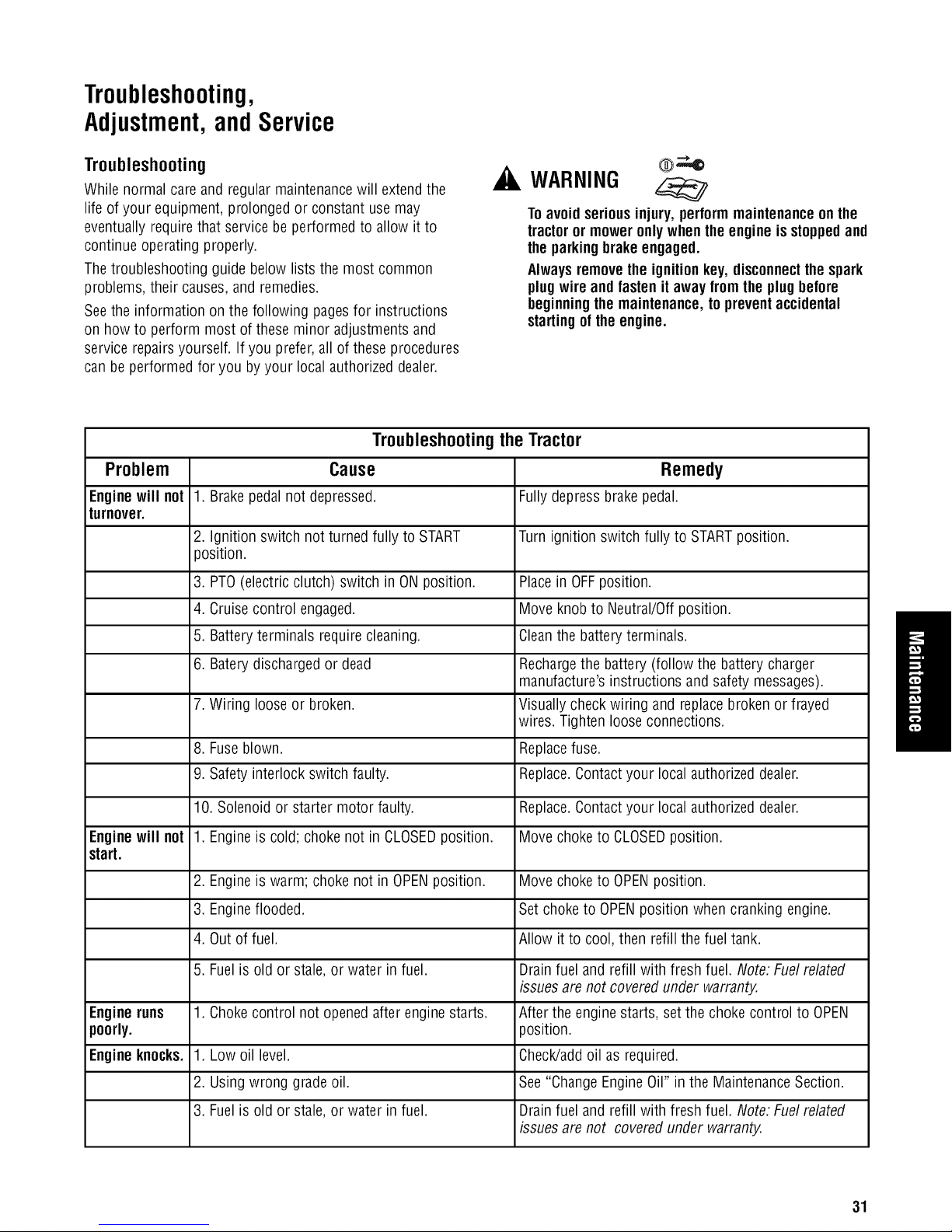
Troubleshooting,
Adjustment,andService
Troubleshooting
While normal care and regular maintenancewill extendthe
life of your equipment, prolonged or constant use may
eventually requirethat service be performed to allow it to
continue operating properly.
Thetroubleshooting guide below lists the most common
problems, their causes,and remedies.
Seethe information on the following pagesfor instructions
on how to perform most of these minor adjustmentsand
service repairsyourself. If you prefer, all of theseprocedures
can beperformed for you by your local authorized dealer.
TroubleshootingtheTractor
Problem Cause Remedy
Enginewill not 1. Brakepedal not depressed. Fullydepress brake pedal.
turnover.
2. Ignition switch not turned fully to START Turn ignition switch fully to STARTposition.
position.
WARNING
Toavoidseriousinjury, performmaintenanceonthe
tractoror moweronlywhentheengine is stoppedand
theparkingbrakeengaged.
Alwaysremovethe ignitionkey, disconnectthespark
plugwire and fastenitaway fromthe plugbefore
beginningthemaintenance,to preventaccidental
startingof theengine.
3. PTO(electric clutch) switch in ONposition. Placein OFFposition.
4. Cruisecontrol engaged. Move knob to Neutral/Offposition.
5. Batteryterminals require cleaning. Cleanthe battery terminals.
6. Baterydischarged or dead Rechargethe battery (follow the battery charger
manufacture'sinstructions andsafety messages).
7. Wiring loose or broken. Visuallycheck wiring and replacebroken orfrayed
wires. Tightenlooseconnections.
8. Fuseblown. Replacefuse.
9. Safetyinterlock switch faulty. Replace.Contactyour local authorized dealer.
10. Solenoidor starter motor faulty. Replace.Contactyour local authorized dealer.
Enginewill not 1. Engineis cold; choke not in CLOSEDposition. Movechoke to CLOSEDposition.
start.
2. Engineis warm; choke not in OPENposition. Move choketo OPENposition.
3. Engineflooded. Set choketo OPENposition when cranking engine.
4. Outof fuel. Allow it to cool,then refill the fueltank.
5. Fuelis old or stale,or water in fuel. Drainfuel and refill with fresh fuel. Note:Fuel related
issuesare not covered under warranty.
Engine runs 1. Chokecontrol not opened after enginestarts. After the engine starts, set the chokecontrol to OPEN
poorly, position.
Engineknocks. 1. Low oil level. Check/addoil as required.
2. Usingwrong gradeoil. See "ChangeEngineOil" in the MaintenanceSection.
3. Fuelis old or stale,or water in fuel. Drainfuel and refill with fresh fuel. Note:Fuel related
issuesare not covered under warranty.
31
Page 76

Troubleshootingthe Tractor(Continued)
Problem Cause
Excessiveoil consumption. 1. Engine running too hot.
2. Too much oil in crankcase.
3. Using wrong weight oil.
Engineexhaustis black.
Engineruns,but tractorwill not
drive.
.
Chokeset to CLOSEwhen engine
is running.
.
oo much oil in crank case.
1.
Parking brakeis engaged.
2.
Ground speed control pedals not
depressed.
Transmission releaselever in
3.
"push" position.
.
Drive belt slips.
Drive belt is broken
5.
Remedy
Cleanengine fins, blower screen andair
cleaner.Cleanradiator screen.
Checkthe oil level, drainexcess oil as
required.
See"Change EngineOil" in the
MaintenanceSection of operator's manual
for complete oil specifications.
Setchoke to OPENas soon as engine
starts.
Checkthe oil level, drainexcess oil as
required.
Disengageparking brake.
Depress3edals.
Stop engmeand move into drive
position.Seeyour Dealer.
Seecause and remedy below.
Seeyour Dealer
Tractordrivebelt slips.
Brakewill nothold.
Tractorsteershardor handles
poorly.
1.
Pulleys or belt greasy or oily.
Belt stretchedor worn.
2.
3.
Idler pulley pivot bracket "frozen"
in declutched position.
Internal brakeworn.
1. Seeyour dealer.
1.
Improper tire inflation
Cleanas required.
Seeyour Dealer.
Removeidler pulley bracket, cleanand
lubricate.
Checkand correct.Checkandtighten any
loose connections. SeeSteeringGear
Adjustment.
2. Front wheel spindle bearingsdry.
GearAdjustment.Greasespindles. See
Tractorand Mower Maintenancein the
Maintenancesection.
3. Steering linkage is loose.
Checkand correct.Checkandtighten any
loose connections.
32 snapper.com
Page 77

Troubleshootingthe Mower
Problem Remedy
Mower will not raise. 1. Attachor repair.
Mower cut is uneven.
Mower cut is rough looking.
Enginestalls easilywith mower
engaged.
Excessivemower vibration.
Lift linkagenot properly attached
or damaged.
,
Mower not leveledproperly.
2.
Tractortires not inflated equally or
properly.
.
Engine speedtoo slow.
2.
Ground speed too fast.
Bladesare dull.
3.
.
Mower drive belt slipping because
it is oily or worn.
5.
CheckPTO(Electric Clutch)
Adjustment.
6.
Bladesnot properly fastened to
arbors.
1.
Engine speedtoo slow.
2.
Ground speed too fast.
3.
Dirty or cloggedair filter.
4.
Cutting height settoo low.
5.
Dischargechute jamming with cut
grass.
6.
Engine not up to operating
temperature.
7.
Starting mower intall grass.
1.
Blade mounting screws are loose.
2.
Mower blades, arbors,or pulleys
are bent.
3.
Mower bladesare out of balance.
Cause
See Leveling the Mower in this section.
See Regular Checksin the Maintenance
section.
Setto full throttle.
Slow down.
Sharpen or replaceblades.See Tractorand
Mower Maintenancein the Maintenance
section.
Cleanor replace belt as necessary.
SeeAdjustments section.
See Tractor and Mower Maintenancein the
Maintenancesection.
Setto full throttle.
Slow down.
SeeEngine Maintenancein the
Maintenancesection.
Cut tall grass at maximum cutting height
during first pass.
Cut grass with discharge pointing toward
previously cut area.
Runenginefor severalminutes to warm-
up.
Start the mower in aclearedarea.
Tighten to 45-55 ft-lb (61-75 Nm).
Checkand replaceas necessary.
Remove,sharpen,and balanceblades. See
Tractorand Mower Maintenancein the
Maintenancesection.
Excessivebelt wear or breakage.
Mower drive belt slips or fails to
drive.
4. Belt installed incorrectly.
1. Bent or rough pulleys.
2. Using incorrect belt.
1. Idler pulley spring brokenor not
properly attached.
2. Belt stops out of adjustment.
3. Mower drive belt broken.
4. PTOclutch out of adjustment.
Reinstallcorrectly.
Repairor replace.
Replacewith correct belt.
Repairor replaceas needed.
Checkbelt stops.
Replacedrive belt.
Adjust PTOclutch.
33
Page 78

Adjustments
PTOClutchAdjustment
Seat Adjustment
Theseat can be adjustedforward and back.Move the lever
(A, Figure30), position the seat as desired,and releasethe
leverto lock the seatinto position.
Figure30: Seatadjustment
A - SeatAdjustment Lever
BatteryCharging
WARNING
Keepopenflames andsparksaway fromthe battery;
thegassescomingfrom it are highlyexplosive.
Ventilatethe batterywell duringcharging.
A dead battery or one too weakto start the engine may be
the result of a defect in the charging system or other
electrical component. If there is anydoubt about the cause
of the problem, seeyour dealer.If you needto replacethe
battery, follow the steps under Battery Maintenance in the
Maintenancesection.
Tochargethe battery,follow the instructions provided bythe
battery charger manufactureras well as allwarnings
included in the safety rules sections of this book. Chargethe
battery until fully charged.Donot chargeat a rate higher
than 10 amps.
WARNING
Toavoidseriousinjury, performadjustmentsonly
with enginestopped,keyremovedandtractor on
level ground.
Checkthe PTOclutch adjustment after every250 hours of
operation. Also perform the following procedure if the clutch
is slipping or will not engage,or if a newclutch has been
installed.
1. Remove key from ignition switch and disconnect spark
plug wires to prevent the possibility of accidental
starting while the PTOis beingadjusted.
2. See Figure31. Notethe position of the 3adjustment
windows (A) in the sideof the brake plateand the
nylock adjustment nuts (B).
3. Insert a .012 in.-.015 in. (2,5-4 mm) feeler gauge(C)
through eachwindow, positioning the gauge between
the rotor faceandthe armature face as shown in
Figure32.
4. Alternatelytighten the adjustment nuts (B, Figure31)
until the rotor face andarmature face just contactsthe
gauge.
5. Checkthe windows for an equal amount of tension
when the gaugeis inserted and removed,and makeany
necessaryadjustments bytightening or loosening the
adjustment nuts.
Note: Theactual air gapbetween the rotor and armature may
vary even after performing the adjustmentprocedure. Thisis
due to dimensional variations on component parts, and is an
acceptablecondition.
6. Checkthe mower bladestopping time. The mower
bladesand mower drive belt should come to a
complete stop within five seconds after the electric PTO
switch isturned off.
7. Perform the BladeBrakeCheckfound in the
Maintenancesection. Mower bladesand mower drive
belt should cometo a completestop within five
seconds afterelectric PTOswitch is turned off.
BrakeAdjustment
This unit does not havea manually adjustablebrake. If brake
does not function properly seeyour dealer.
34 snapper.com
Page 79

Figure31: PTOclutch adjustment
A - Adjustment Window (Qty.3, one shown)
B - Adjustment Nut
MowerAdjustments- GaugeWheels
Themower gauge wheelscan be placedin two positions
depending on the height of cut. When using highercutting
heights, setthe wheels in the lower position. When using
lower cutting heights, set the wheels in the upper position.
Donot allow wheelsto remainon the ground constantly
while mowing. To adjust:
1. Remove the Iocknut (B, Figure 33), gauge wheel (C),
washers (D), and shoulder bolt (E). Changeposition of
gaugewheel to desired height.
2. Insert shoulder bolt (E)through washers (D) gauge
wheel (C),and gaugewheel bracket(A). Secure with
Iocknut (B). Repeatsteps 1 and 2 for all gaugewheels.
Figure32: Adjust PTOclutch
A - Window
B - Adjustment Nut
C - FeelerGauge
Figure33: Fixedbracket gauge wheeladjustment
A - GaugeWheel Bracket
B - Locknut
C- GaugeWheel
D- Washer
E - Shoulder Bolt
35
Page 80

Service LevelingtheMower
FuseReplacement
Thefuse is a 20-amp bladetype automotivefuse located
behind the batteryon the steering tower. Replaceonly with
the sameratedfuse, 20-amp.
Toreplacethe fuse:
1. Openthe hoodand locate the fuse holder (B, Figure34)
and fuse (A). Attached to the steeringtower.
2. Hold the fuse holder (B) and pull outthe fuse (A).
3. Inspect the fuse for a broken fusible link. SeeFigure 35.
Replacefuse if connection is broken. If you are not
sure if the fusible link is broken replacefuse.
4. Hold the fuse holder (B, Figure34) and insert newfuse
(A) until it is seated properly.
Figure34. Fuse
A - Fuse,20-amp
B - FuseHolder
Cm m
m
m
i i
I
t i
Figure35. Bladetype fuse
A - Goodfuse with solid fusible link
B - Blown fuse with broken fusiblelink
mm
mm
JL
mm
WARNING
Beforecheckingmower,shutoff PTOand engine,
removethekey,and allow all movingpartstostop.
If the cut is uneven,the mower may needleveling. Unequal
or improper tire pressuremay also causean unevencut.
Make sure tire pressure is correct as specified in Checking
TirePressure in the Maintenancesection.
Side-to-SideLeveling
1. With the mower installed, placethe tractor on a
smooth, levelsurface suchas a concretefloor. Turn the
front wheels straight forward.
2. Checkfor bent bladesand replace if necessary.
3. Placethe mower in mid-cut position. Arrangethe
outside mower bladesso that they arepointing from
side-to-side.
4. Measurethe distancebetweenthe outsidetips of each
blade and the ground. If there is more than 1/8 in.
(3 mm) difference betweenthe measurementson each
side, proceedto step 5. If the difference is 1/8 in.
(3 mm) or less, proceed to step 6.
5. Turn the Iocknut (B, Figure 36) to raiseor lower that
side of the mower.
Note: Themaximum the mower can be adjustedin high cut
is 3/8 to 1/2 in. (10 to 13mm) betweenthe frame and
mower up-stop. SeeFigure41.
Front-to-Back Leveling
6. Arrange the bladesso they facefront-to-back.
7. Measurethe distancefrom the ground to the front tip
of the center blade,and from the ground to reartips of
left-hand and right-hand blades.
Front tip of the centerbladeshould be1/4 in. (6 mm) higher
than reartips of left-hand andright-hand blades.If not,
proceedwith step 8.
8. To raise front of mower deck, tighten Iocknuts (A,
Figure36) and againstspacers (B). To lowerfront of
mower deck, loosen Iocknuts (A). Locknuts must be
turned evenlyon both sides to keepdeck level.
9. Re-checkthe blademeasurement then tighten thefront
nut (B)against the bracketto secure.
36 snapper.com
Page 81

Figure36: Levelingthe mower side-to-side
A - Lift Rod
B - Locknut
C - 3/8 in. - 1/2in. (10 - 13 mm) max inhigh cut
Figure37. Levelingthe mower side-to-side
A - Locknuts
B- Spacers
Mower Belt Replacement
NOTICE Q
Toavoiddamagingbelts, do notprybelts over
pulleys.
Note: It is not necessaryto remove the mower to install a
new belt. However,for easieraccess mower can be removed.
SeeMower DeckRemovalin the Assembly section.
1. Park the tractor on a smooth, levelsurface such as a
concretefloor. Disengagethe PTO,turn off the engine
and lock the parking brake. Removethe key.
2. If mower is not removed,lower the mower lift and
placethe mower in the lowest cutting position.
3. Push the idler arm (A, Figure38) to relievebelt tension.
Drop the belt from the PTO (electric clutch) pulley.
Note:Make note of the position of all belt guides relative to
thebelt andpulleys before loosening.
4. Some Models. Loosenthe beltstop bracket(s) (C).
5. Remove the old belt and replacewith a new belt. Make
sure V-side of belt runs in arbor pulley groovesand the
flat backside runs againstthe idler pulley.
6. Some Models. Position the belt stop bracket(s) (C) in
their original positions. Theremust be1/8 in. (3 mm)
clearancebetweenthe belt stopand the pulleys.
7. Position the idler pulley belt guide (D) in its original
position up against arm (A)so that there is a1/8 in.
(3 mm) gap betweenthe pulleyand belt guide.
8. Install mower on tractor if it was removed. See
Assembly section.
9. Run the mower under no-loadcondition for about
5 minutes.
JlI v
FRONT
Figure38: Typicalmower belt routing three blade decksas
viewedfrom left side of mower
A - Idler Pulley Arm
B- PTOPulley (Engine)
C- BeltStop Bracket
D- Idler Pulley BeltGuide
37
Page 82

Effective December 1, 2005 replaces all undated Warranties and all Warranties datedbefore December1, 2005
LIMITED WARRANTY
Briggs & Stratton Yard Power Group, LLCwill repair or replace,free of charge, any part(s) of the lawn tractor that is defective in material or
workmanship or both. Transportation charges on product submitted for repair or replacement under this warranty must beborne by purchaser.This
warranty is effective for the time periods and subject to the conditions stated below. For warranty service, find the nearestAuthorized Service Dealer in
our dealer Iocator map at SNAPPER.COM.
The manufacturer warranties to the original purchaser that each new product listed below is merchantable and free from defects in workmanship and
material. This warranty is effective for the time periods listed below and is subject to the conditions that are provided in this policy. No other warranty or
implied warranty bythe manufacturer exists except where required by law. The company's liability arising out of warranties, representations,
instructions, or defects from any cause shall be limited exclusively to repair or replacing parts under the conditions inthis warranty, and in no event will
the company be liable for incidental or consequential damages. Some states do not allow the exclusion or limitation of incidental or consequential
damages,so the above limitation or exclusion may not apply to you. This warranty givesyou specific rights that vary from state to state.
The warranty period begins on the date of purchase by the first retail consumer or commercial end user, and continues for the period of time stated above.
"Consumer use" means personal residential household use by a retail consumer. "Commercial use" means all other uses, including usefor commercial,
income producing or rental purposes. Onceequipment has experiencedcommercial use, it shall thereafter be considered as commercial use for purposes of
this warranty.
NOWARRANTY REGISTRATIONIS NECESSARYTOOBTAINWARRANTYON BRIGGS& STRATTONPRODUCTS.SAVEYOUR PROOFOF PURCHASE
RECEIPT.IFYOU DONOT PROVIDEPROOFOFTHEINITIAL PURCHASEDATEATTHETIME WARRANTYSERVICEIS REQUESTED,THE MANUFACTURING
DATEOFTHE PRODUCTWILL BEUSEDTO DETERMINETHE WARRANTYPERIOD.
WARRANTY PERIOD:
1. Repair parts installed on products receivethe same warranty period remaining for the product or 90 days consumer use and45 dayscommercial use,
whichever is longer. Repair partssold over the counter havea 90 day warranty for residential use and a 45 day warranty for commercial use.
2. Batteries have a one year warranty for residential or commercial use.
OWNERRESPONSIBILITIES:
To qualify for warranty service, the purchaser of a Snapper product must:
1. Send inthe Product Registration Card at the time of purchase.
2. Notify a Snapper Dealer as soon as possible after discovery of apossible defect. If you are not aware of your nearestSnapper dealer, write for such
information to SnapperProducts., Attn: Service Dept., 535 Macon Street McDonough, GA 30253 or refer to the yellow pages of your telephone
directory under Lawn & Garden Equipment. If you arenot aware of your nearest Snapperdealer (888) 477-8650.
NOTCOVEREDBYWARRANTY:
The following are not covered by this Limited Warranty:
1. Damagecaused by misuse of the product or by operating the product in excess of recommended capacities.
2. Damagecaused by negligence oraccident.
3. Products which havebeen altered or repaired in a manner not authorized by Snapper.
4. Certain components, someattachments, and some transaxles are warranted separately bytheir respective manufacturers.
5. Normal maintenance and/or replacement of maintenance and wear items such as oil, filters, blades, belts, brakes andclutch linings.
6. Problems caused by the use of non-Snapper repair parts. Problems causedby the use attachments not approved by Snapper.
7. Products which havebeen sold to a second owner.
8. All engine service, warranty or otherwise, is required to be performed by a manufacturer-authorized service center. Snapper is neither authorized nor
responsible for anytype of warranty engine service, nor is it equipped to perform any such service.
WARRANTY IS AVAILABLE ONLY THROUGH AUTHORIZED SNAPPER DEALERS.
38 snapper.com
BRIGGS & STRATTON YARD POWER GROUP, LLC
MILWAUKEE, WI, USA
Page 83

PartsandAccessories
Parts
ReplacementParts
Replacementparts areavailablefrom your authorizeddealer.
Always usegenuine Simplicity Service Parts.
MaintenanceItems
Many convenient and helpful service and maintenanceitems
are availablefrom you authorized dealer.Some of these
items include:
Engine Oil Tire Sealant
Touch-UpPaint Degrimer/Degreaser
GreaseGun Kit GasStabilizer
8 oz. GreaseTube
TechnicalManuals
Additional copiesof this manualare available,as well asfully
illustrated parts lists. Thesemanuals show all of the
product's components in explodedviews (3D illustrations
which show the relationship of parts and howthey go
together) aswell as part numbersand quantities used.
Important assembly notesand and torque valuesare also
included.
Forapplicable manualscurrently availablefor your model,
contact our CustomerPublications Department at 877-249-
6647. Havethe information listed in the box below available
when phoning in your request. Technicalmanuals can be
downloadedfrom
www.snapper.com
39
Page 84

LT-200 Series Hydro Tractors and Mower Decks
Note: Specificationsare correct at time of printing and aresubject to changewithout notice.
Specifications
20 hp*Description
Engine
Make / Model
Horsepower
Displacement
ElectricalSystem
Oil Capacity
Oil Type
Air Filter
Spark Plug
Spark PlugGap
Chassis
FuelTankCapacity
RearWheels
Front Wheels
Transmission
Type
HydraulicFluid
Speeds@3400 rpm
Reverse:0-3.0 MPH(4.6 km/h)
ContinuousTorqueOutput
Drawbar Rating
Maximum Weight onAxle
Dimensions
OverallLength 72 in (183 cm)
OveralWidth 37 in (94 cm)
Weight 532 Ib (241 kg)
Briggs & Stratton / Intek
20 @ 3600 rpm
30.5 ci (582 cc)
12 Volt, 9 amp. Alternator, Battery:230 CCA
64 oz (1.9 L)
SeeOperator's Manualor Engine Manual
792105
491055
.76mm or 0.030 in.
3.5 gal (13.2 L)
22 x 10 -8 TireSize: 10 psi (.68 bar) Inflation Pressure
15 x 6 -6 Tire Size:12-14 psi (.82-.96 bar) Inflation Pressure
Hydrostatic Tuff Torq K46
10W30 PremiumEngineOil
Forward: 0-5.5 MPH(9.0 km/h)
170 ft-lb
227 Ib (103 kg)
675 Ib (306 kg)
with 44 in Mower Deck
* The gross power rating labels for individual gasengine models is labeled inaccordance with SAE (Society of Automotive Engineers) code J1940 (Small
Engine Power & Torque Rating Procedure), and rating performance hasbeen obtained and corrected in accordance with SAEJ1995 (Revision2002-05).
Actual gross engine power will be lower and is affected by, among other things, ambient operating conditions and engine-to-engine variability. Given both the
wide array of products on which engines are placed and thevariety of environmental issues applicable to operating the equipment, the gas engine will not
develop the rated gross power when used in agiven pieceof power equipment (actual "on-site" or net horsepower). This difference is due to a variety of
factors including, but not limited to, accessories (air cleaner,exhaust, charging, cooling, carburetor, fuel pump, etc.), application limitations, ambient operating
conditions (temperature, humidity, altitude), and engine-to-engine variability. Dueto manufacturing and capacity limitations, Briggs & Stratton may substitute
an engine of higher rated power for this Series engine.
Snapper Products
535 Macon Street
IVIcDonough,GA30253 (800) 935-2967
snapper.com C_
 Loading...