


Thank you for buying a SNAPPER product! Before operating your mower, read this manual carefully and pay particular attention to the important Safety instructions on page 2. Remember that mowers and all power equipment can be dangerous if used improperly and keep in mind that safety requires careful use in accordance with the instructions and....common sense!
This Operator's Manual covers SERIES 9 (last number in the five digit model designation) REAR ENGINE RIDING MOWERS. The first two digits indicate the width of cut. The next two digits give the horsepower rating. Models having an "E" suffix are Electric Start.
#1-6849 (Rev.1, 6/92)
# 1-6849 manuals search engine
SERIES 1
McDonough. GA., 30253 U.S.A.
IMPORTANT SAFETY INSTRUCTIONS
WARNING: This powerful cutting machine is capable of amputating hands and feet and can throw objects that can cause injury and damage! Failure to observe the following safety instructions could result in serious injury. Carefully read this manual and question your dealer if something is not clear. Should the dealer be unable to answer to your satisfaction, write or call the Customer Service Department at SNAPPER Power Equipment, McDonough, Georgia 30253 (phone 404-957-914!).
PROTECTION FOR CHILDREN
- 1. DO NOT allow children or pets in yard when mower is operated.
- 2. DO NOT allow children to ride on mower or attachments.
- 3. DO NOT ALLOW pre-teenage children to operate mower.
- 4. Only responsible teenagers with mature judgement, physical size and strength to reach and operate controls shall be allowed to operate mower and only under close mature adult supervision.
PROTECTION AGAINST TIPOVERS
- 1. DO NOT operate mower on slopes exceeding 15° (27% grade).
- 2. On slopes above 10° (18% grade); exercise extreme caution; turn blade OFF when traveling uphill; do not mow across; reduce speed to No. 1 position, avoid sharp turns and uphill starting.
- 3. AVOID UPHILL STARTS. If machine is stopped going up slope, turn blade off and back slowly down slope.
- DO NOT mow under any condition where traction or stability is doubtful without first test driving over terrain with blade OFF.
- 5. Stay alert for holes and other hidden hazards and keep away from ditches, washouts, culverts, fences and protruding objects.
- 6. Always begin forward motion in No. 1 speed position.
- 7. Use weighted load carrier on front when using grass catcher on slopes above 10° (18%)grade.
OTHER IMPORTANT PRECAUTIONS
- 1. Read and follow operator's manuals and instructions furnished with attachments.
- 2. Only mature, responsible persons shall operate the mower.
- 3. Mount and dismount mower from left side.
- 4. Wear appropriate protective clothing when mowing such as substantial footwear and long pants, not barefoot or with open sandals.
- 5. Practice operation of mower with blade OFF to learn controls and develop skill.
- Persons under the influence of alcohol or drugs must not operate mower.
- 7. Know how to stop blade and engine quickly in preparation for emergencies.
- 8. Keep people and pets a safe distance from mower.
- 9. Shields, deflectors, switches, blade controls and other safety devices must be in proper position and functional.
- 10. Clear area to be mowed of wire, rocks and other objects that could cause injury if thrown by blade.
- 11. Stop the blade, shift to NEU (neutral) and set parking brake whenever leaving mower momentarily with engine running. Make sure blade is stopped by seeing that the belt is not moving.
- 12. When leaving the mower unattended; shut off engine, shift to a forward speed, set parking brake and remove key.
- 13. DO NOT operate mower unless properly seated with feet on pads or pedals.
- 14. Keep hands and feet away from rotating blade underneath deck. Never place feet on ground while blade is ON or when mower is in motion!
- 15. Turn blade OFF, stop engine and wait for blade to stop before attempting to unclog grass or leaves.
- 16. Blade must be shifted OFF except when cutting grass. Set deck in highest position when mowing over rough ground.
- 17. Deflector or grass catcher must be in position. Never point discharge at people, passing cars, windows or doors. Watch out for traffic when crossing or near roadways.
- 18. Mow in reverse only after careful observation of entire area behind the mower. DO NOT mow in reverse unless absolutely necessary.
- 19. Service mower and make adjustments only when engine is stopped.
- 20. Have mower serviced by an authorized SNAPPER dealer at least once a year and have the dealer install any new safety devices.
- 21. Use only genuine SNAPPER replacement parts to assure that original standards are maintained.
- 22. Tighten all nuts, bolts and screws frequently and check, adjust, repair or replace brakes as needed.
- 23. Lubricate mower at intervals specified in manual to prevent controls from binding.
- 24. Mow only in daylight or in good artificial light.
- 25. Handle gasoline with care! Never remove cap while engine is running. Fill tank outdoors only with engine stopped and cool. Clean spilled gasoline from machine. Store gasoline in approved container, out of the reach of children, in well ventilated, unoccupied building.
- 26. DO NOT run engine indoors. Exhaust fumes are dangerous. Carbon monoxide is a colorless and odorless gas which can seriously impair the health of persons and pets!
- 27. DO NOT change engine governor speed settings or overspeed engine.
- 28. Check grass catcher components frequently for signs of wear or deterioration and replace as needed to prevent thrown objects from going through weak or worn spots.
- 29. Exercise caution when pulling loads. Limit loads to those you can safely control and attach loads to hitch plate as specified with SNAPPER attachment instructions.
Downloaded from www.Manualslib.com manuals search engine
INTRODUCTION
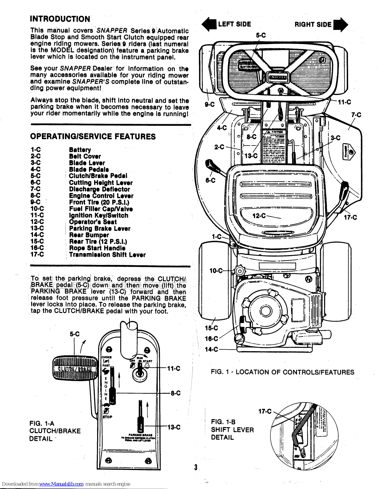
This manual covers SNAPPER Series 9 Automatic Blade Stop and Smooth Start Clutch equipped rear engine riding mowers. Series 9 riders (last numeral is the MODEL designation) feature a parking brake lever which is located on the instrument panel.
See your SNAPPER Dealer for information on the many accessories available for your riding mower and examine SNAPPER'S complete line of outstanding power equipment!
Always stop the blade, shift into neutral and set the parking brake when it becomes necessary to leave your rider momentarily while the engine is running!
OPERATING/SERVICE FEATURES
| 1-C | Battery |
|---|---|
| 2.C | Belt Cover |
| 3-C | Blade Lever |
| 4-C | Blade Pedals |
| 5-C | Clutch/Brake Pedal |
| 6-C | Cutting Height Lever |
| 7-C | Discharge Deflector |
| 8-C | Engine Control Lever |
| 9-C | Front Tire (20 P.S.I.) |
| 10-C | Fuel Filler Cap/Valve |
| 11-C | Ignition Key/Switch |
| 12-C | Operator's Seat |
| 13-C | Parking Brake Lever |
| 14-C | Rear Bumper |
| 15-C | Rear Tire (12 P.S.I.) |
| 16-C | Rope Start Handle |
| 17-C | Transmission Shift Lever |
To set the parking brake, depress the CLUTCH/ BRAKE pedal (5-C) down and then move (IIft) the PARKING BRAKE lever (13-C) forward and then release foot pressure until the PARKING BRAKE lever locks into place. To release the parking brake, tap the CLUTCH/BRAKE pedal with your foot.


- FIG. 1 LOCATION OF CONTROLS/FEATURES
- FIG. 1-B SHIFT LEVER DETAIL

Downloaded from www.Manualslib.com manuals search engine
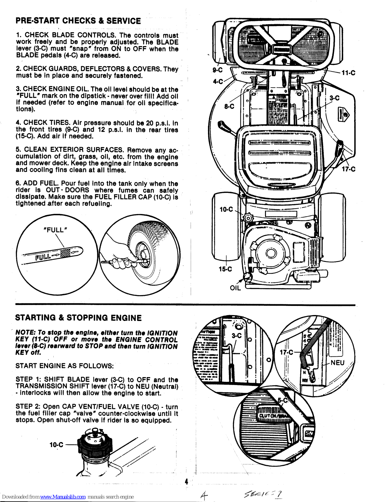
PRE-START CHECKS & SERVICE
1. CHECK BLADE CONTROLS. The controls must work freely and be properly adjusted. The BLADE lever (3-C) must "snap" from ON to OFF when the BLADE pedals (4-C) are released.
2. CHECK GUARDS, DEFLECTORS & COVERS. They must be in place and securely fastened.
3. CHECK ENGINE OIL. The oil level should be at the "FULL" mark on the dipstick - never over fill! Add oil if needed (refer to engine manual for oil specifications).
4. CHECK TIRES. Air pressure should be 20 p.s.i. in the front tires (9-C) and 12 p.s.l. in the rear tires (15-C). Add air if needed.
5. CLEAN EXTERIOR SURFACES. Remove any accumulation of dirt, grass, oil, etc. from the engine and mower deck. Keep the engine air intake screens and cooling fins clean at all times.
6. ADD FUEL. Pour fuel into the tank only when the rider is OUT - DOORS where fumes can safely dissipate. Make sure the FUEL FILLER CAP (10-C) is tightened after each refueling.

STARTING & STOPPING ENGINE
NOTE: To stop the engine, either turn the IGNITION KEY (11-C) OFF or move the ENGINE CONTROL lever (8-C) rearward to STOP and then turn IGNITION KEY off.
START ENGINE AS FOLLOWS:
STEP 1: SHIFT BLADE lever (3-C) to OFF and the TRANSMISSION SHIFT lever (17-C) to NEU (Neutral) - interlocks will then allow the engine to start.
STEP 2: Open CAP VENT/FUEL VALVE (10-C) - turn the fuel filler cap "valve" counter-clockwise until it stops. Open shut-off valve if rider is so equipped.


56R1657
Downloaded from www Manualslib com manuals search engine
STEP 3: CHOKE ENGINE - To start a cold engine, move Engine Control Lever (8-C) to the CHOKE position.
STEP 4: MANUAL START ENGINE - Turn the Ignition Key (11-C) to RUN and pull rope Start Handle (16-C) to start engine.
STEP 4-A: ELECTRIC START ENGINE - Turn the Ignition Key (11-C) to START and hold until engine starts.
Release the key (to cool starter) if the engine has been cranked for approximately 5 seconds and fails to start. Then try again.
NOTE: Should the battery ever be too weak to electrically start the engine, manually start it with the ROPE START handle (16-C). Remove the battery and connect to charger. Never "Boost" charge a battery to prevent possible battery damage, always slow ("Trickle") charge a battery.
STEP 5: ENGINE WARM-UP - After a brief period at the CHOKE position, move the Engine Control Lever (8-C) rearward until the engine runs smoothly. Set the lever at or near FAST for best cutting and bagging performance.
STEP 6: STOP ENGINE by turning the Ignition Key (11-C) left to OFF or by moving the Engine Control Lever (8-C) rearward to STOP.
STARTING/STOPPING RIDER
Become thoroughly familiar with the location and function of the forward & reverse direction controls: CLUTCH/BRAKE pedal (5-C), PARKING BRAKE Lever (13-C), and the TRANSMISSION SHIFT lever (17-C) (refer to FIG. 1).
FORWARD DIRECTION: When partially depressed, the CLUTCH/BRAKE pedal (5-C) functions as a clutch, permitting shifting from neutral into either forward or reverse. Further depression of the pedal provides braking. When depressed, the pedal can be set for parking (refer to FIG. 1-A).
After shifting the TRANSMISSION SHIFT lever (17-C) into the #1 speed position, release the pedal to begin forward movement. Move the lever forward or rearward while traveling forward (without depressing the pedal) to shift into higher or lower FORWARD speeds.
NOTE: The rider can roll if the TRANSMISSION SHIFT Lever (17-C) is in neutral and the parking brake is NOT set!
REVERSE DIRECTION: Before shifting into reverse, fully depress the CLUTCH/BRAKE pedal (5-C) to stop. Move the TRANSMISSION SHIFT lever (17-C) rearward into REV position and then completely release the pedal to begin moving in reverse. To stop while in reverse, fully depress the pedal.


STARTING & STOPPING MOWER BLADE
The Automatic Blade Stop Controls should stop the blade in less than 3 seconds - after the BLADE pedals (4-C) are released. The BLADE lever (3-C must be shifted forward first, then the pedals are depressed to keep the blade engaged.
NOTE: The BLADE lever will NOT move forward if the BLADE pedals are depressed first
Start and Ston blade as follows:
STEP 1. Shift BLADE lever forward to ON and hold in position. Then depress the BLADE pedals - keep your heel(s) on the pedals to "lock" the blade into the mowing (rotating) sequence.
NOTE: If STEP 1 is followed, the blade will rotate whenever the engine is running.
STEP 2: To stop the blade, remove your heel(s) from the BLADE pedals. The spring loaded BLADE lever will then snap rearward to OF
NOTE: The BLADE lever can be forced into OFF position while the BLADE pedals are depressed, by bushing the BLADE lever inward, and then pull rearward into OFF
NOTE: If the BLADE lever moves SLOWLY rearward rather than snapping back, the belt may be too slack, or the linkage may need lubrication.
Adjust the belt and lubricate the mower (as described in the SERVICE section). and check the blade stopping time. If the time exceeds 3 seconds, adjust the blade brake as described on page 9. If the stopp-ing time still exceeds 3 seconds, the mower should not be operated until inspected/repaired by your dealer.
SERVICE
SERVICE ASSISTANCE/REPLACEMENT PARTS
By returning your mower to an Authorized SNAPPER Dealer on a yearly basis for inspection and addition of any new devices to upgrade your mower, the safety of the unit's functions will be assured
Check the yellow pages under LAWNMOWERS for the nearest SNAPPER Dealer. Always mention the model and serial number of your mower when contacting the dealer for parts, service, or information.
For engine parts/service, check under ENGINES - gasoline, for nearest engine manufacturer's dealer.
NOTE: Always take the following steps before standing your SNAPPER rear engine rider on the REAR BUMPER.
- 1. TIGHTEN FUEL FILLER CAP (10-C) 2. CLOSE (TURN CLOCKWISE) THE VENT VALVE ON FUEL FILLER CAP (10-C
- 3. REMOVE THE BATTERY (1-C) IF THE UNIT IS TO BE STOOD ON END LONGER THAN 2 HOURS.


It is recommended that rear engine riders sit on the REAR BUMPER during the servicing of lubrication points on the underside. When preparing to raise the front. position BOTH hands near the center of the front frame "lip" to prevent any possibility of having fingers pinched by the rods.
It is recommended that you use Genuine SNAPPER Replacement Parts to retain the integrity of your mower
SERIES 9
LUBRICATION SCHEDULE
EVERY 25 OPERATING HOURS:
• FRONT WHEEL BEARINGS: Lubricate through grease fittings (6-L) with bearing grease from a pressure gun. 6 H.P. units do not have grease fittings.
REAR LEFT AXLE BEARING: Riders powered by B or 6.5 h.p. engines are equipped with a grease fitting (8-L). Lubricate through the fitting with 2 shots of bearing grease from a pressure gun.
NOTE: The rear right axle bearing is lubricated by the transmission on all models.

ENGINE: Change oil per instructions in engine manual. Check oll level before each use
● AIR CLEANER: Clean and/or replace air cleaner element(s) per instructions in engine manual.
It is recommended that the air cleaner be periodicallv inspected when adding fuel, and inspected more frequently when the machine is operated in dry dusty environments.
EVERY 6 MONTHS:
• CUTTING HEIGHT LEVER (6-C): Remove the BELT COVER (2-C) from deck and apply a small amount of medium grade cup grease to top surface of adjusting cams on both sides, and lubricate idler arm.
• BLADE LEVER (3-C); Lubricate idler arm and engagement lever at each wear point with a few drops of oil. Also lube arm at pivot to spindle housina.
• BLADE PEDALS (4-C): Lubricate all pivoting and sliding surfaces where motion occurs (when pedals are moved) with a few drops of oil. Reinstall BELT COVER


| - | BLADE PEDAL · Pivot Points |
|---|---|
| _ | BLADE SPINDLE · Grease Fittings |
| _ | CHAIN CASE - Check Plug |
| _ | CLUTCH CABLE |
| DIFFERENTIAL - Check Plug | |
| FRONT WHEEL - Grease Fittings | |
| SHIFT ARM - Pivot Points | |
| REAR AXLE - Grease Fitting | |
| YOKE - Plyot Points | |
| _ |
1.1
2-| 3-| 5-| 6-| 7-|
8-1
9.
FIG 2 - LUBBICATION & SERVICE POINTS

FIG 2-B
SERIES 1
ONCE A YEAR
STAND MOWER ON REAR BUMPER
• BLADE SPINDLE : Two shots of grease through grease fitting (2-L) is required. The fitting is between the deck and the blade.

• DIFFERENTIAL: Remove the DIFFERENTIAL CHECK PLUG (5-L) at A. If the level of grease is below the bottom edge of hole, add SNAPPER 0 grease until it reaches the bottom edge, by removing the plug at B and filling the differential through that hole. Install new plugs after servicing.
• CHAIN CASE: Remove CHAIN CASE CHECK PLUG (3-L) and add about 1 ounce of SNAPPER 0 grease to case if low - avoid over filling. Total capacity must not exceed 2 ounces. Install new plug.
FUEL FILTER
The in-line filter (between fuel tank and engine) protects the engine from damage due to gasoline impurities. Also, check the hose clamps for any leakage. Replace the filter ( SNAPPER #1-4359) before the screen becomes completely clogged with sediment. When the filter appears dark (in the screen area), and/or if the engine becomes "starved" for fuei - it will not accelerate properly, misses, or stalls under load, the filter should be replaced.
OPERATOR'S SEAT
The Operator's Seat (12-C) may be moved either forward or toward the rear of unit to enable individuals of varying heights to comfortably steer and control the rider.
To adjust the seat, loosen the 2 three prong knobs (A) located on the underside of the slotted mounting bracket. Move the seat in the desired direction, and then retighten both knobs.
Also, for taller operators, the offset steering wheel may be rotated 180 degrees. If assistance is needed, contact your SNAPPER Dealer.

*With mower standing on end
FIG. 4 - DIFFERENTIAL LUBE LEVEL

FIG. 5 - CHAIN CASE

FIG. 6 - FUEL TANK & FILTER

FIG. 7 - CHECK SEAT RETAINER SCREWS NOTE: 6 & 6-1/2 H.P. models are not equipped with THREE PRONG KNOBS (A).
1.54018 S 1
BELT TENSION ADJUSTMENT & REPLACEMENT
Shut the engine off first! DISCONNECT THE SPARK PLUG WIRE, and then remove the belt cover.
With the mower deck in #5 height position and the blade in the ON position, check the distance between the inside surfaces of the belt as shown in FIG. 9. The belt tension is adjusted by changing the "distance" between the front axle and the rear case. Loosen nut (Y) at the main tube clamp (X) beneath the main channel (under seat) and pull the front assembly FORWARD to increase belt tension until the correct amount is achieved. Then retighten nut(Y).
After "distance" has been changed, check operation of the clutch/brake pedal and readjust the brake control cable, if needed, for proper traction and braking. Refer to the Brake section.
If belt becomes frayed, cracked, or worn, replace as follows: Remove the BELT COVER, then cut and remove the old belt. To install new belt, close fuel cap (10-C) valve. Stand mower on REAR BUMPER (14-C), shift into NEU. position, work belt between discs, shift into #5 speed and push belt over edge of engine drive disc. Work into the groove of the drive disc, then connect other end to pulleys on mower deck as follows: Loosen or remove the idler pulley, loop the belt around spindle pulley as shown in FIG. 9 and work belt between restrictor and idler pulley. Make sure locking tab on restrictor is engaged in idler arm before securing idler arm nut and bolt. Check and adjust belt tension as needed before reinstalling BELT COVER.
BLADE BRAKE ADJUSTMENT
As the brake band wears, the BLADE lever will gradually stop further rearward in the slot of the BELT COVER. BRAKE adjustment is required when the lever stops 1/2" from the top of the belt cover. The adjusting point is shown in FIG. 11. With the engine stopped, the adjustment is made as follows:
STEP 1: Lower cutting deck and remove the BELT COVER.
STEP 2: While holding the BLADE lever firmly in the rearward position, loosen the jam-nut on the end of the eye bolt (refer to FIG. 11).
STEP 3: Move the BLADE lever to the ON position, press the BLADE pedals down and hold, then turn the T-nut on end of eye bolt (clockwise) several complete turns. Make sure tab on T-nut is positioned vertically to fit over the anchor.
STEP 4: Release the BLADE pedals to allow the BLADE lever to move to the OFF position, then depress the BLADE pedals again and check the clearance between forward edge of the BLADE lever and the rear edge of the latch plate which should be less than 1/4" (FIG. 10). Repeat the procedure in step 2 if needed to obtain correct clearance. When correct, hold the BLADE lever rearward and turn the jam-nut tight against the T-nut to lock in new position. Reinstall BELT COVER

WHEEL BRAKE TEST & ADJUSTMENT
Test the wheel braking action at frequent intervals to insure proper stopping in the event of possible emergencies. Normally, the rider should stop from FAST (top forward speed) within approximately three feet after the CLUTCH/BRAKE pedal has been fully depressed.
WARNING: Always disconnect the spark plug wire and secure the end away from the plug before inspecting/servicing the rider/mower, to prevent unintentional start-ups.
Prior to making brake adjustment, check to see that the mower belt is adjusted properly.
Stand the rider on its REAR BUMPER (14-C), engage the PARKING BRAKE (13-C), shift the TRANSMIS-SION SHIFT lever (17-C) to the #3 speed position, and then check the distance between the DRIVEN DISC rubber drive ring and the surface of the drive disc. There should be between 1/16" and 1/8" clearance.
If the proper distance is not evident, the clutch/brake cable needs to be adjusted. Release the parking brake, rotate the clutch yoke to provide slack in the cable, and then move 1 of the spacers (Y) through the "keyhole" slot in the top of clutch arm (X) to the end of cable. Re-engage the parking brake and again check the clearance between the rubber ring and the drive disc. Repeat this procedure until the proper distance in achieved.
CLUTCH ADJUSTMENT
Adjustment is made by repositioning the yoke lift spring. Initially the spring is hooked through the #2 hole (second from end) in the clutch link - there are 4 holes. With the spring hooked in the #2 hole, the clutch will have smooth action under normal loads. Hook the spring in #1 hole to pull heavier loads. If when releasing foot pressure on the CLUTCH/BRAKE pedai (5-C), the rider tends to "hop" rather than start forward or reverse motion smoothly, hook the spring through hole #3 or #4 to attain smoother starts.
CUTTING BLADE SERVICE
BE CAREFUL: Avoid cutting yourself on a sharp blade! Wear gloves to protect your hands while handling the blade.
Check the blade at frequent intervals for proper tighteness and operating condition. Replace if chipped, bent or notched. Sharpen if in otherwise good condition-at an angle of 22-28 degrees inward about 2-1/2" from tips. Check blade for balance and correct to prevent vibration. Install the blade with retaining hardware as shown in FiG. 14 and tighten to torque specified.
Check levelness (straightness) of the blade "TIPS". Mark one (A) and the other (B). Scribe a mark on the deck at the lip. By rotating the blade, measure the distance "TIP" (A) and then "TIP" (B) each are from the marked lip.
To adjust the brake (with the parking brake on), loosen both jam nuts (A) which secure the clutch/brake cable threaded tube (B) to the chain case bracket as shown. Then, by screwing the two jam nuts up or down, the tube can be moved to change the distance the cable end is recessed INSIDE the spring guide (tube), which is attached to the brake lever. Adjust the threaded tube up or down until the cable end is recessed between 1/8"to 3/8" from the cotter pin. Retighten both jam nuts (A) against bracket (C)


Additional adjusting can be made by moving the other threaded tube up or down. It is located under/inside the front of the main channel and above the mower deck.

If there is a difference of more than 1/16" between the two measurements, level the "TIPS" by loosening the two jam nuts, and turn each of the two jackscrews either clockwise or counter-clockwise until the "TIPS" are within 1/16" of each other. Then retighten the jam nuts against the blade bar.
NOTE: If after inspection, the blade tips are found to rotate closer to one point on deck lip, the lateral position of spindle housing needs to be re-centered by your Authorized SNAPPER Dealer.

CUTTING DECK SERVICE
If the mower cuts an "uneven" swath, follow the procedures below:
1. Slow the rider's forward movement (shift into a lower range) and move the ENGINE CONTROL LEVER (8-C) toward FAST.
2. Check belt tension (refer to BELT ADJUSTMENT section).
3. If the cut is uneven from side to side, check tire pressure. The front should be 20 p.s.i. and the rear are properly inflated at 12 p.s.i.
4. If an uneven pattern persists, roll the rider onto a smooth, flat, level surface (such as a garage floor), turn the ignition key (11-C) to OFF, and be sure the BLADE lever (3-C) is in the OFF position. Check the mower deck settings as follows:
SIDE TO SIDE LEVEL (30" & 33"): Raise deck and place a triangular block (such as a piece of angle iron) under the rear (at the center) and lower the deck onto the block.
A. On 33" mowers, measure the clearance between the lower outside edge of the deck and the floor (the right side and left side). There should be 1/8" or less difference between the two measurements.

To level the deck, adjust the ECCENTRIC (located on the front LEFT mower lift arm). Loosen the shoulder bolt, rotate the eccentric toward UP or toward DOWN as needed and hold in place while retightening the shoulder bolt. Then, again measure the distance to the floor as described in A after removing the block.

FRONT TO REAR ADJUSTMENT: The distance the mower deck is from the ground surface is pre-set at an optimum level. Should the deck pitch ever need to be "fine tuned", the adjusting nut "A" should be screwed in or out only by a technician at your SNAP-PER Dealer. Timing rod "B" maintains the levelness of the deck - front to rear as the deck is raised or lowered.

Downloaded from www.Manualslib.com manuals search engine
To resetdeck (distance from ground surface), adjust rear lift bracket at hanger cables. Raise deck, and place block under center rear of deck-under lip. Lower deck onto block to permit some slack in cables. By relocating the same number of spacers on each cable above the keyhole slot in each "arm" of the lift bracket, the rear of deck will be lowered; placing an equal number of spacers below the slot in each "arm" raises the deck. Raise deck and remove block.

A. On H+-VAC mowers, measure the distance from the front and rear lower edges of the deck to the floor. The rear edge should be level with, or no more than, 3/8" lower than the front edge.
B.On mowers with the 26" deck, align one blade tip to face the front of rider and measure the distance from the tip to the floor. Rotate the blade and measure the distance (from the same tip) to the floor while the tip is facing the rear of rider. The distance at the rear should be 1/8" to 5/8" more than at the front.

NOTE: Blade to floor clearance may be measured through the deck discharge opening (raise discharge deflector).
Contact your SNAPPER Dealer if the "uneven" mowing pattern remains - after inspecting and adjusting.
BATTERY SERVICE
Check the fluid in the battery at frequent intervals to make sure the level is above the MIN. FILL line. To keep the fluid in proper range, remove the cell caps and add distilled water as needed to bring the level in each cell up to but not over, the MAX. FILL line. In freezing weather, always charge the battery after adding water. The engine is equipped with a flywheel alternator to maintain battery charge when run frequently. Keep the specific gravity of the battery above 1.250--if lower than 1.175, the battery liquid may freeze at temperature around zero degrees Fahrenheit. If battery charge is low, disconnect terminal wires and recharge on an automotive type charger following instructions provided with the charger. For best results, slow charge 1 amp for 10 hours or if time does not permit, fast charge at 3 amp rate for 4 hours. Always disconnect the battery negative terminal first and reconnect it last. Keep the red boot over the positive terminal!
BATTERY STORAGE
Recharge the battery once each month during the off season storage period. To prevent damage due to exposed cells, remove the wet cell type battery before standing the mover on end during storage Store the battery in a vented area preferably where temperatures remain above 32 degrees Fahrenheit. but not too warm. DO NOT store a battery on a concrete floor
STORAGE PROCEDURE
If desired, stand the mower on end during off-season storage provided the following steps are taken beforehand:
1. Remove wet cell type battery (see BATTERY STORAGE)
2. Thoroughly clean surfaces and lubricate machine (See | UBRICATION SERVICES).
3. Drain fuel from tank and close vent on the fuel filler cap.
4. Service engine for storage as described in the engine owner's manual.
After storing on end, the following steps are required to prepare the engine for operation again. Turn the IGNITION SWITCH off and pull the ROPE START HANDLE slowly. If excessive resistance is felt or if the engine refuses to rotate, remove the spark plug and pull handle again to clear cylinder of oil. Clean and reinstall the spark plug.
MOWING HINTS
Before starting to mow move the ENGINE CON-TROL lever forward (into the FAST position). Set TROL lever forward (into the FAST position). Set the TRANSMISSION SHIFT lever in a mid range set. ting and the CUTTING HEIGHT lever in a raised nosition
Then, experiment and adjust cutting height and forward speed until the mower is functioning best for your particular conditions.
NOTE: The engine is designed to be run at "FULL THROTTLE " while the grass is being cut
□ If the around is drv and dusty, and grass is sparse, be aware that the vacuum action of the blade will create a dust storm! Also, when fertilizing the lawn with a drv-type fertilizer, don't use the mower until after there has been a shower or the lawn has been enrinkled
Changing your mowing pattern from time to time creates a smoother cut lawn. Finely chopped clippings add nutrients to the soil to promote grass growth. However, if accumulation becomes too heavy, matting develops and thatch is formed which prevents breathing, holds excessive moisture, and can destroy root structure
The SNAPPER Thatcherizer (Thatcherizer Kit #6-0948) is the answer to this problem. It will prevent such destruction from occuring by dislodging excessive thatch, thus enabling you to vacuum, sweep, or rake and remove any harmful accumulation as well as expose twids and any other debris
| NADADAU | For two (2) Years from purchase date for the original purchaser's residential, non-commercial use [ninety (90) days from purchase date for the original purchaser's commercial, rental, or other non-residential use], SNAPPER, through a SNAPPER dealer will replace, free of charge, any part or parts found upon examination by the factory at McDonough, Georgia, to be defective in material or workmanship or both. |
| CANAL CONTRACT | All transportation cost incurred by the purchaser in submitting material to a SNAPPER dealer for replacement under this warranty must be borne by the purchaser. |
| NUMU | This warranty does not apply to engines and their components, as these items are warranted separately by their manufacturers, and does not apply to batteries which are covered separately. This warranty does not apply to parts that have been damaged by accident, alteration, abuse, improper lubrication, normal wear, or other cause beyond our control. |
| No. | There is no other express warranty. |
| Implied warranties, including those of merchantability and fitness for a particular purpose, are limited to two (2) years from purchase date for the original purchaser's residential, non-commercial use innety (90) days from purchase for the original purchaser's commercial, rental or other non-residential use, and to the extent permitted by law any and all implied warranties are excluded. This is the exclusive remedy. Liabilities for consequential damages, under any and all warranties are excluded. | |
| NAU N | Some states do not allow limitations on how long an implied warranty lasts,or do not allow the exclusion or limitation of incidental or consequential damages, so the above limitation or exclusion may not apply to you. |
| This warranty gives you specific legal rights, and you may also have other rights which vary from state to state. | |
| DAUM |
WARNING: THE USE OF REPLACEMENT PARTS OTHER THAN GENUINE SNAPPER PARTS MAY IMPAIR THE
SAFETY OF SNAPPER PRODUCTS AND WILL VOID ANY LIABILITY AND WARRANTY BY SNAPPER ASSOCIATED WITH THE USE OF SUCH PARTS. |
| NAU | IMPORTANT: Please fill out the attached SNAPPER Product Registration Card immediately and mail to: SNAPPER, McDONOUGH, GEORGIA 30253 |


 Loading...