

1
Installation
Instructions
Attachment Lift Kit
Mfg. No. 1694148
For Broadmoor / 1600 / 2600 Series Tractors
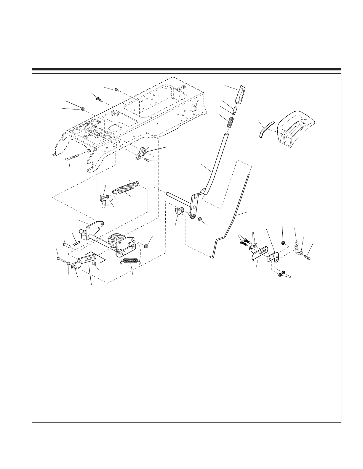
Figure 1. Contents
Mower
Lift Arm
Torque to
23-28 ft. lbs.
(31-38 Nm)
Rotate clockwise
as far as possible
before tighting.
Assemble into
lower hole of Ref. Item 20.
11
19
17
21
12
20
16
18
13
22
23
24
1
29
16
28
26
27
16
8
30
8
2
7
4
5
6
3
9
10
10
14
15
25
31
Kit Contents:
Ref Part No. Qty. Description
1 1927557 2 NUT, Flange, 5/16-18
2 1931333 3 CARRIAGE BOLT, 5/16-18 x 3/4
3 1722291 1 GRIP, Lift Lever
4 1723124 1 BUTTON, Red Nylon, for 1/4 Rod
5 1960518 1 NUT, Push
6 1723321 1 SPRING, Compression, Lift Lever
7 1721581 1 QUADRANT, Lift, Powdered Metal
8 926149 6 CAPSCREW, 5/16-18 x 1, G8
9 1721712 1 LEVER ASSEMBLY, Lift
10 1960636 5 NUT, Hex, 5/16-18
11 1722482 1 ROD, Latch
12 1722112 1 LOCK, Lift, Powdered Metal
13 2156302 1 SPRING, Extension
14 1723163 1 SPACER, 1/2 x 3/4 x 23/32
15 1723795 1 BAR, Lift Link
16 1919381 7 WASHER, 5/16, Black
Ref Part No. Qty. Description
17 1921160 1 CAPSCREW, 5/16-18 x 2-1/4
18 1722819 1 PIN, Flat Hd, 1/2 x 2-1/8
19 1960033 1 CLIP, Hair Pin, 2-9/16 Long
20 1721654 1 SHAFT ASSEMBLY, Lift
21 1935255 1 NUT, Speed, 5/16-18, Lug
22 1675232 1 SPRING, Extension
23 1723499 1 RETAINER, Spring Flat
24 1722357 1 CAPSCREW, 5/16-18 x 4-1/2
25 1724378 1 COVER, Hand Control
26 1707514 2 CHAIN, 3-Link
27 1930570 2 CAPSCREW, 5/16-18 x 1-1/2
28 1919438 2 NUT, Nylock, 5/16-18
29 1724432 2 ARM, Lift, Duel, Mower
30 1931277 4 NUT, Whizlock, 5/16-18
31 1921221 1 CARRIAGE BOLT,
5/16-18 x 1-1/2
2
Installation Instructions Lift Lever Kit
INSTALLATION
1. Remove the mower deck (see operator’s manual).
Remove Seat Deck & Tunnel
1. Elevate the rear of the tractor, and support the tractor
on jackstands. Remove the right rear wheel.
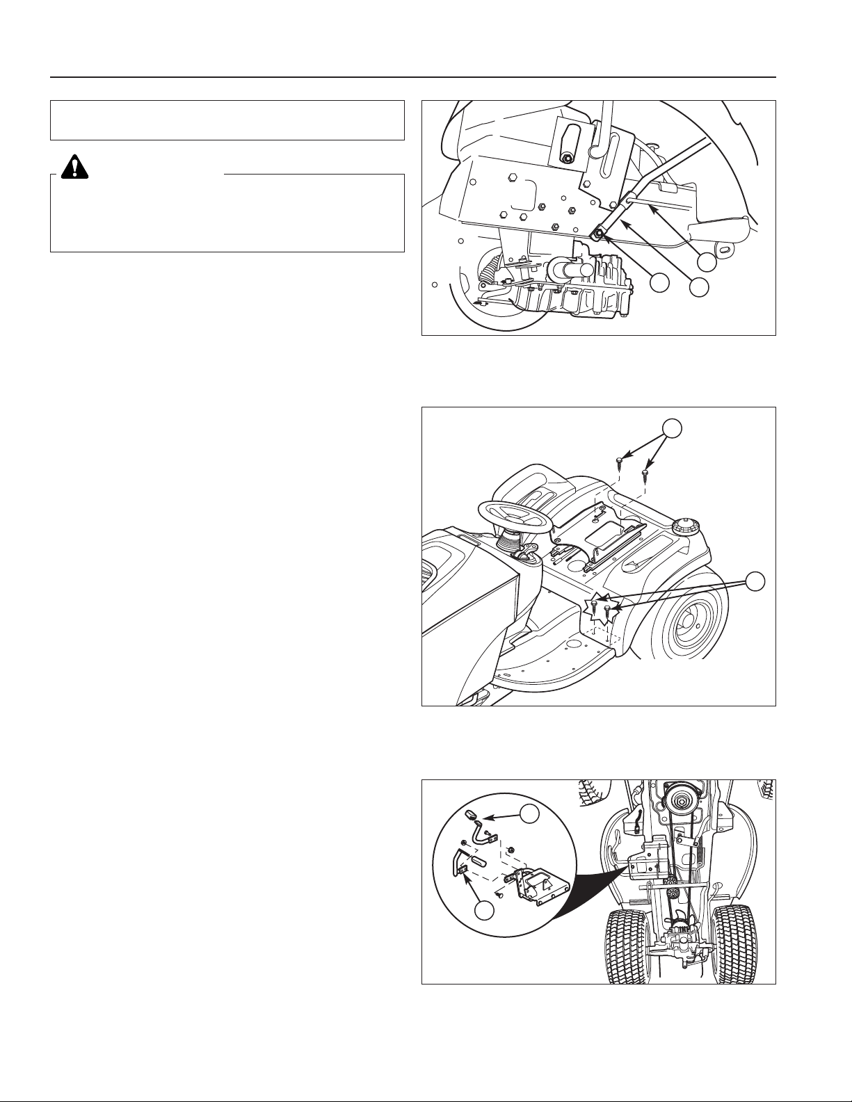
2.
50” MOWER DECKS
Remove and discard the lift lever pivot capscrew (A,
Figure 2) and related hardware. Disconnect and discard the rod (C) and lift lever (B).
38”, 40” & 44” MOWER DECKS
Remove and retain the lift lever pivot capscrew (A,
Figure 2) and related hardware. Disconnect and discard the rod (C) and lift lever (B).
3. Disconnect the seat switch wire harness. Remove
the wire harness from the clip.
4. Move the seat slide to access the two top seat deck
capscrews (B, Figure 3). Remove the capscrews.
5. Remove the four bolts (A, Figure 3) securing the front
of the seat deck to both footrests.
6. Remove the gas cap.
7. Remove the cruise control knob (if equipped).
8. Remove the seat deck.
This kit adds an attachment lift lever to
Broadmoor/1600/2600 Series lawn tractors.
Before beginning any service work turn off the
PTO, set the parking brake, turn off the ignition,
and disconnect the spark plug wire(s).
WARNING
Figure 3. Seat Deck Removal
A. Foot Rest Screws (Two per Side)
B. Top Seat Deck Screws
B
A
Seat Removed
for Clarity
Figure 2. Seat Deck Removal
A. Pivot Capscrew C. Rod
B. Lift Lever
A
C
B
A
A
Figure 4. Pedals
A. Foot Pedals
9. Remove the foot pedals (A, Figure 4) and any
remaining screws securing the tunnel to the frame.
10. Pull back on the footrests (tunnel) and remove the
tunnel from the frame.
11. Remove the lift lever slot plastic plug from the lower
dashboard.
3
Lift Lever Kit Installation Instructions
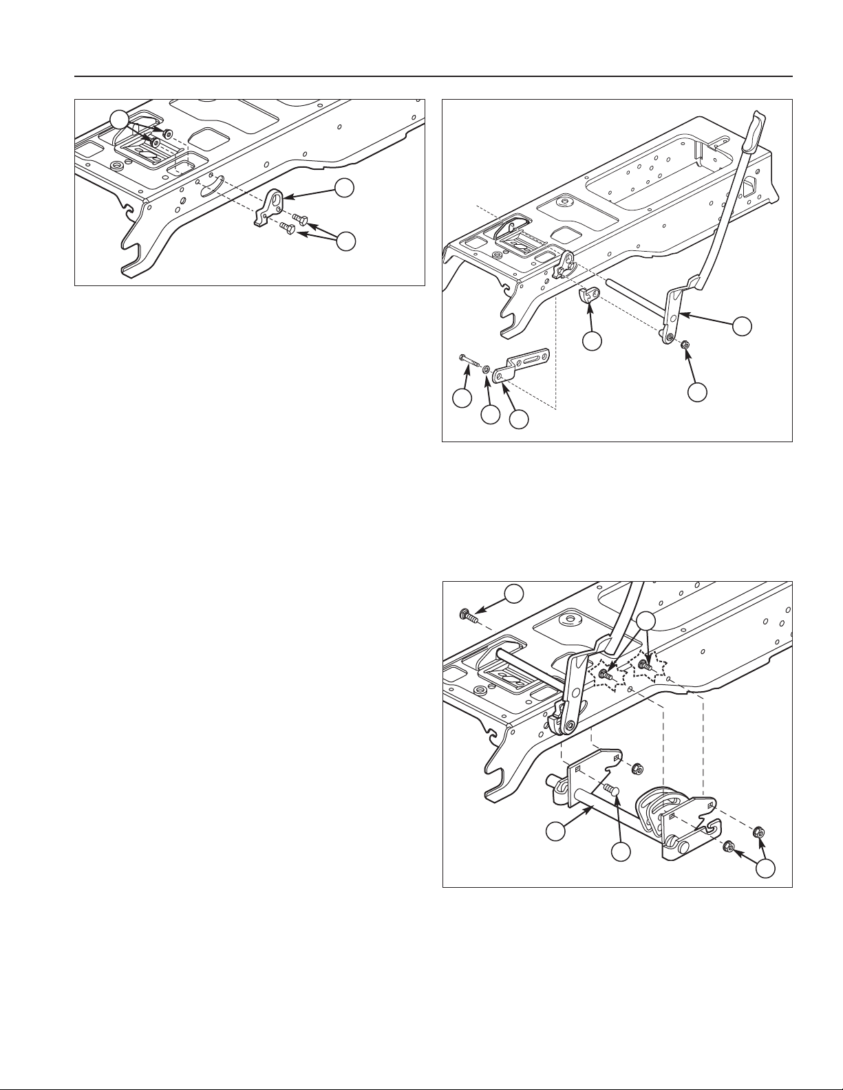
Install Lift Lever & Lift Shaft Assembly
1. Install the lift quadrant (B, Figure 5) using two 5/1618 x 1 grade 8 capscrews (C) and flange nuts (A).
2. Insert the lift lever (F, Figure 6) through the quadrant,
frame, and lift latch (D). NOTE: Route the wire harness and fuel line above the lift lever cross bar. DO
NOT pinch the fuel line and wire harness between
the cross bar and frame.
3. Insert a 5/16-18 x 2-1/4 capscrew through a 5/16
washer (B), lift bar (C), frame, lift latch (D), and lift
lever (F). Secure with a 5/16 locknut.
4. Mount the lift shaft assembly (A, Figure 7) to the
frame using three 5/16-18 x 3/4 carriage bolts (B),
5/16-18 x 1-1/2 carriage bolts (D) and flange nuts (C).
Note: If the unit has a single point pick-up for the mower
reinstall the bell crank to the rear right lift shaft hole.
B
C
A
Figure 5. Install Lift Quadrant
A. Flange Nuts, 5/16-18
B. Lift Quadrant
C. Capscrews, Grade 8, 5/16-18 x 1
F
E
D
C
B
A
Figure 6. Install Lift Lever
A. Capscrew, 5/16-18 x 2-1/4
B. Washer, 5/16
C. Lift Bar
D. Lift Latch
E. Locknut 5/16-18
F. Lift Lever
Figure 7. Install Lift Shaft Assembly.
A. Lift Shaft Assembly
B. Carriage Bolts, 5/16-18 x 3/4
C. Flange Nuts
D. Carriage Bolt, 5/16-18 x 1-1/2
B
B
C
A
A

4
Installation Instructions Lift Lever Kit
A
Figure 8. Install Return Spring
A. Return Spring
Install Return Spring
1. Insert the return spring (A, Figure 8) through the lift
shaft assembly from the bottom and hook the front
leg of the spring on the top edge of the lift arm.
2. Route the spring around the bottom of the shaft and
hook the back leg on the notch in the plate.
A
B
C
D
E
A
F
C
D
G
Figure 9. Connect Lift Link
A. Pin
B. Rear Hole of Lift Bar (Snowthrower Applications)
C. Spacer
D. Hair Pin Clip
E. Upper Hole (Snowthrower Applications)
F. Slot of Lift Bar (Mower Applications)
G. Lower Hole (Mower Applications)
Snowthrower
Applications
Mower
Applications
Install Lift Link
1. Connect the lift bar to the lift shaft assembly. Note
that the pin (A, Figure 9), spacer (C), and hair pin clip
(E) are installed in different positions depending on
what attachment is to be used.

5
Lift Lever Kit Installation Instructions
A
B
C
D
E
Figure 10. Install Assist Spring
A. Capscrew, 5/16-18 x 4-1/2
B. Retainer
C. 5/16 Speed Nut
D. Spring
E. Small Hole and Notch in Lift Link
Install Assist Spring
1. Assemble the spring (D, Figure 10), speed nut (C),
retainer (B), and 5/16-18 x 4-1/2 capscrew (A).
2. Hook the back of the spring (D) into the small hole
and notch (E) in the the lift link.
A
Figure 11. Manual Lift Assist Bolt
A. Adjustment Bolt
3. Route the capscrew (A, Figure 11) through the notch
in the frame, and tighten until it remains in position.
After the attachment is installed, tighten until desired
assist is achieved.
6
Installation Instructions Lift Lever Kit
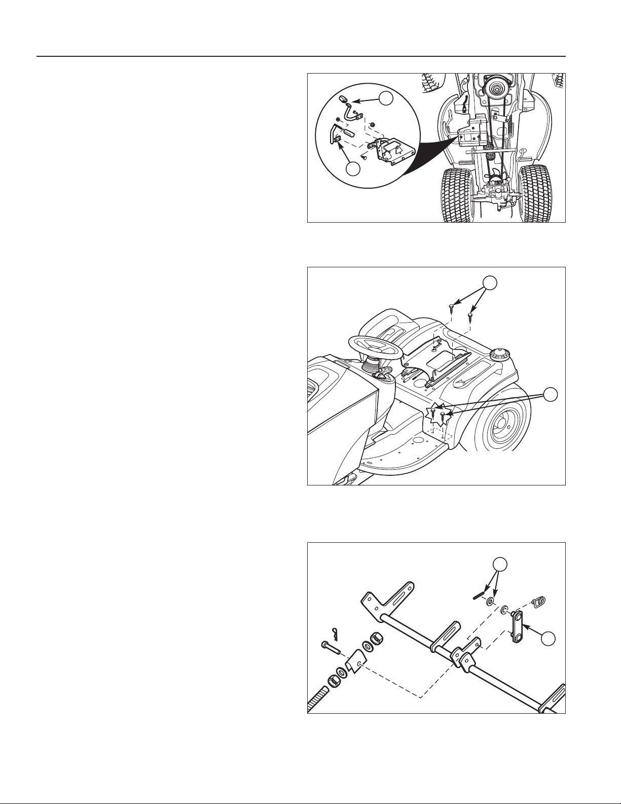
Install Tunnel
1. Set the tunnel on the tractor frame and slide it forward under the dashboard.
2. Secure the tunnel to the frame using the original
hardware.
3. Reinstall the foot pedals (A, Figure 12).
4. Reinstall the cruise control knob.
Modify Mower Deck
ALL MODELS
1. Remove and discard the washer and cotter pin (A,
Figure 14) securing the lift link (B). Retain the lift link
(B). for 38”, 40” and 44” mowers. Discard the lift link
(B) for 50” mowers.
Figure 13. Seat Deck Removal
A. Foot Rest Screws (Two per Side)
B. Top Seat Deck Screws
B
A
Seat Removed
for Clarity
A
A
Figure 12. Pedals
A. Foot Pedals
Install Seat Deck
1. Reinstall the gas tank, if removed. Remove the gas
cap.
2. Set the seat deck down on the seat deck support.
Route the seat switch wire harness though the hole in
the center of the seat deck.
3. Reinstall the gas cap.
4. Secure the seat deck with the original taptite screws
(B, Figure 13), foot rest screws, & nuts.
5. Reconnect the seat switch wire harness.
6. If equipped, install the cruise control knob.
9. Reinstall the right rear wheel.
B
A
Figure 14. Remove Mower Lift Link
A. Washer & Cotter Pin
B. Lift Link

7
Lift Lever Kit Installation Instructions
50" Mower, RH Side
44" Mower, RH Side
38" Mower, RH Side
40" Mower, RH Side
A
A
B
B
B
B
C
C
C
C
D
D
D
D
E
E
E
E
F
F
C
C
G
G
H
H
H
H
Figure 15. Modify Mower Deck - 44” & 50”
A. Whizlock Nut, 5/16-18
B. Nylock Nut, 5/16-18
C. Washers, 5/16
D. Chain Link
E. Capscrew, 5/16-18 x 1-1/2
F. Capscrew, 5/16-18 x 1
G. New Lift Arm
H. Mower Lift Arm
50” MODELS
Note: Old style only
2. Mount a new lift arm (G, Figure 15) on the inside of
both the left and right mower lift arms (H) using two
5/16-18 x 1 capscrews (F), washers (C), and whizlock nuts (A).
3. Secure chains (D) to the inside of the LH and RH lift
arms (G) using a 5/16-18 x 1-1/2 capscrew (E),
washer (C), and nylock nut (B). The nut should be
snug, but the chain should be able to pivot.
44” MODELS
Note: Some models
2. Mount a new lift arm (G, Figure 15) on the inside of
both the left and right mower lift arms (H) using two
5/16-18 x 1 capscrews (F), washers (C), and whizlock nuts (A).
3. Secure chains (D) to the inside of the LH and RH lift
arms (G) using a 5/16-18 x 1-1/2 capscrew (E),
washer (C), and nylock nut (B). The nut should be
snug, but the chain should be able to pivot.
40” MODELS
Note: Some models
2. Secure middle hole of the chains (D) to the inside of
the LH and RH lift arms (H) using a 5/16-18 x 1-1/2
capscrew (E), washer (C), and nylock nut (B). The
nut should be snug, but the chain should be able to
pivot.
38” MODELS
Note: Some models
2. Secure chains (D) to the inside of the LH and RH lift
arms (H) using a 5/16-18 x 1-1/2 capscrew (E), washer (C), and nylock nut (B). The nut should be snug,
but the chain should be able to pivot.

8
Installation Instructions Lift Lever Kit
A
B
C
D
E
A
F
C
D
G
Figure 16. Connect Lift Link
A. Pin
B. Rear Hole of Lift Bar (Snowthrower Applications)
C. Spacer
D. Hair Pin Clip
E. Upper Hole (Snowthrower Applications)
F. Slot of Lift Bar (Mower Applications)
G. Lower Hole (Mower Applications)
Snowthrower
Applications
Mower
Applications
LIFT LINK POSITION
The lift link is installed differently depending on what
attachment is being used. Refer to the illustration at right
for link installation information.
9
Lift Lever Kit Installation Instructions
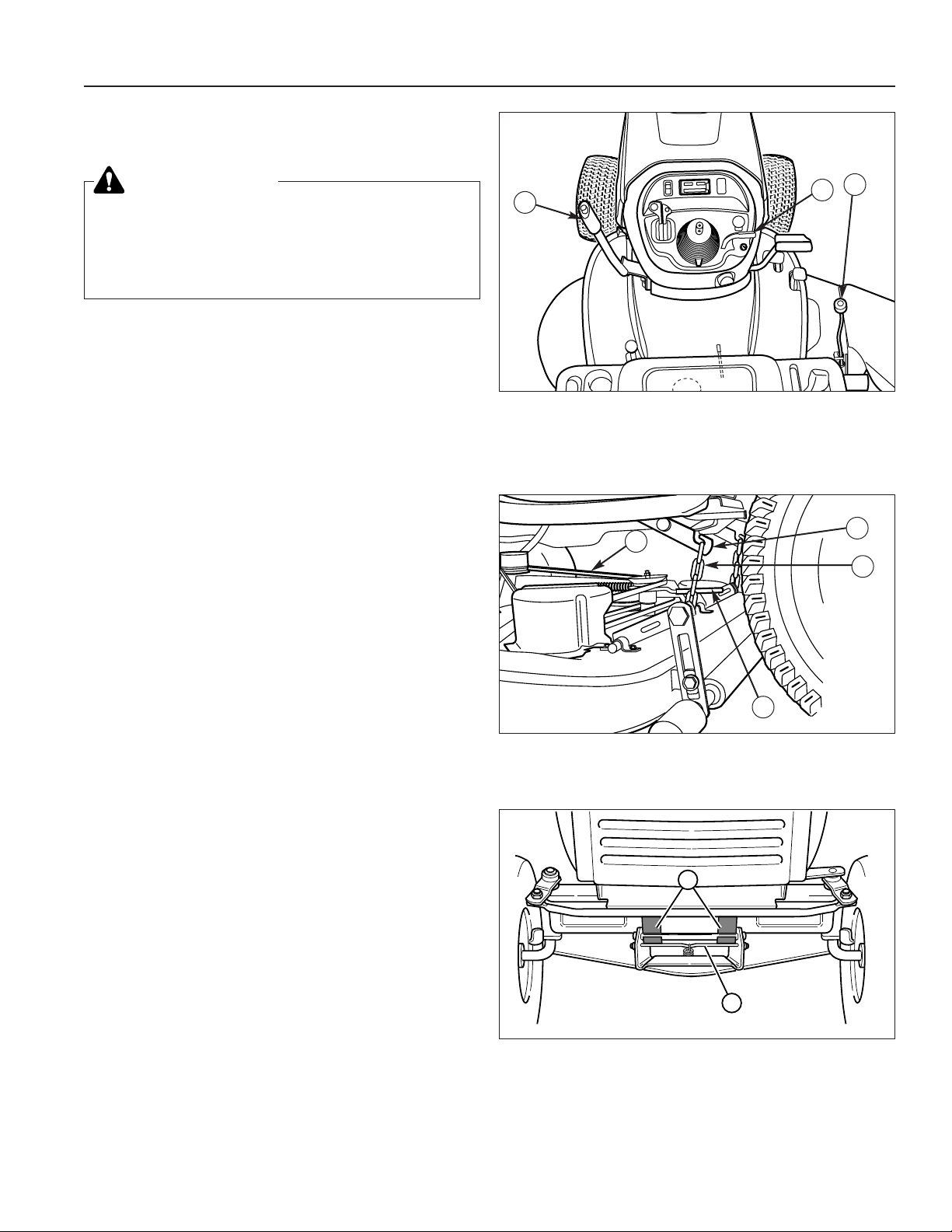
MOWER DECK REMOVAL &
INSTALLATION
Removing the Mower Deck
1. Park the tractor, fully lower the attachment lift, turn off
the PTO, turn off the engine, remove the key, and
engage the parking brake.
2. Place mower in the lowest cutting position using the
mower height control (C, Figure 17).
3. Use the idler arm (D, Figure 18) to release tension on
the PTO belt, and remove belt from the PTO pulley.
4. Pull down on the lift hooks (A, Figure 18) and unhook
the lift chains (B).
5. Turn the wheels straight ahead. Pull back on springloaded lever (B, Figure 19) and lift mower hitch off of
the tractor brackets (A).
6. Turn wheels fully left, and slide mower deck out from
under the right side of the tractor.
Installing the Mower Deck
1. Park the tractor, fully lower the attachment lift, turn off
the PTO switch, turn off the engine, remove the key,
and engage the parking brake. Turn the wheels fully
to the left.
2. Place mower in the lowest cutting position using the
mower height adjuster (C, Figure 17). Slide the
mower deck under the right side of tractor so that the
mower hitch is aligned with front tractor hitch (A,
Figure 19).
3. See Figure 19. Turn wheels straight. Pull back on
the spring-loaded lever (B) while lifting up on the
mower hitch. Install the mower hitch onto tractor hitch
brackets (A). When properly installed, the springloaded lever should seat fully underneath the brackets (A).
4. See Figure 18. Connect the mower lift chains (B) to
the the tractor lift hooks (A).
5. See Figure 18. From left side of tractor, use the idler
arm (D) to relieve belt tension. Install belt (C) onto the
PTO pulley.
WARNING
Engage parking brake, disengage PTO, stop
engine and remove key before attempting to
install or remove the mower.
Muffler and surrounding areas may be hot.
Figure 17. Raising & Lowering Mower
A. Attachment Lift - Manual
B. Attachment Lift - Hydraulic
C. Cutting Height Control
A
A
B
C
D
B
C
Figure 19. Mower Hitch
A. Tractor Hitch Brackets
B. Spring-Loaded Lever
Figure 18. Mower Lift
A. Lift Hook C. PTO Belt
B. Lift Chain D. Idler Arm
A
B

Installation Instructions Lift Lever Kit
Form No. 1723432-02
Rev. 12/2005
© 2005 Simplicity Manufacturing, Inc. All Rights Reserved
TP 200-2580-02-SK-SMA
MANUFACTURING, INC.
500 N Spring Street / PO Box 997
Port Washington, WI 53074-0997 USA
NOTES
 Loading...