

Page 1
Rev. 8/2000
TP 400-2365-00-AT-SMA
Attachment
Illustrated
Parts List
© Copyright 2000 Simplicity Manufacturing, Inc.All Rights Reserved.
MANUFACTURING, INC.
500 N Spring Street / PO Box 997
Port Washington, WI 53074-0997 USA
Page 2
2
TP 400-2365-00-AT-SMA
© Copyright 2000 Simplicity Manufacturing, Inc. All Rights Reserved.
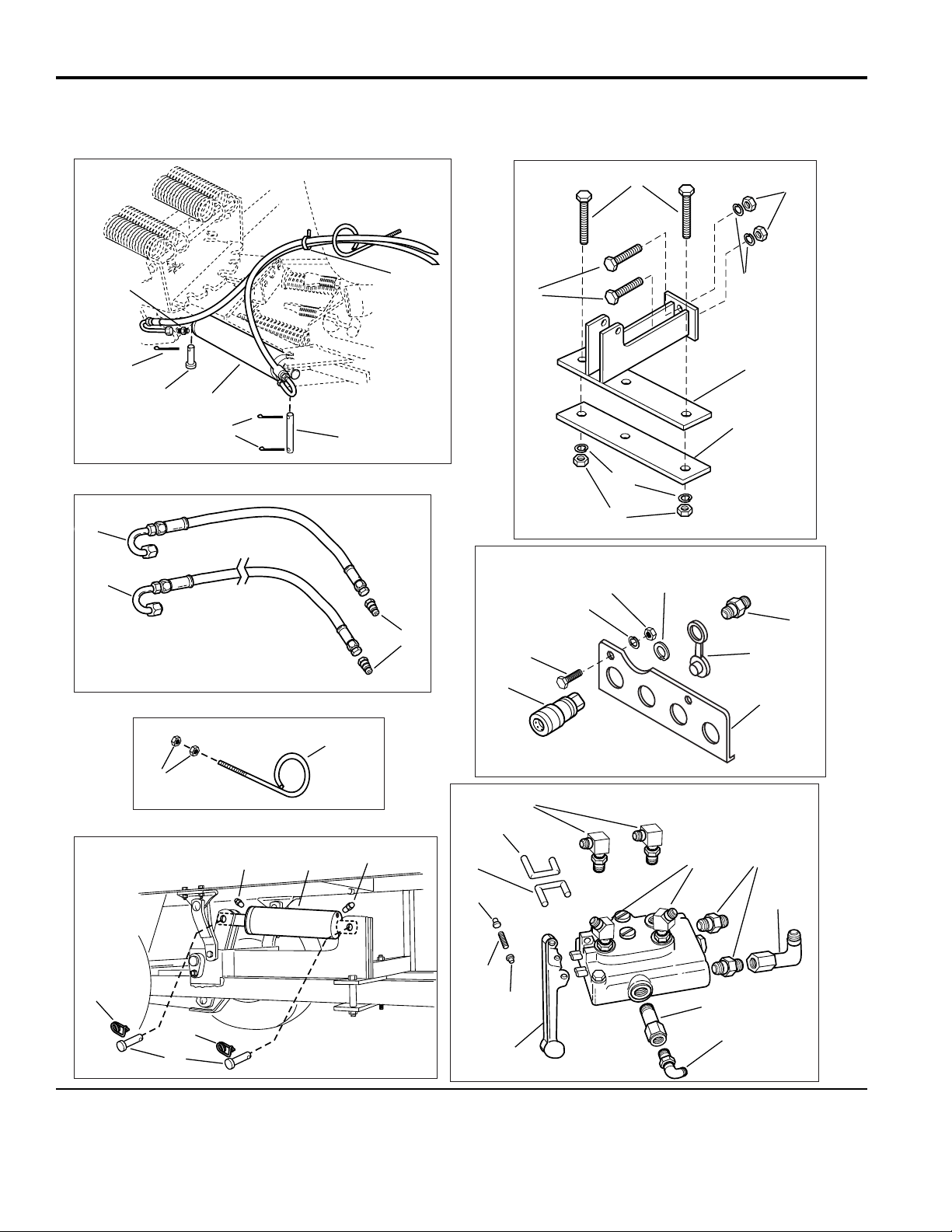
Hydraulic Angling & Lift Group 60” Dozer Blade
NOTE: Unless noted otherwise,
use the standard hardware torque
specification chart.
985457
The above parts group applies to the following Mfg. Nos.:
1693274 Hydraulic Angling & Lift Kit
771
5
6
3
2
4
3
58
9
7
5858511
510
512
512
514
515
510515
513
25
26
27
28
29
23
22
24
30
31
40
539
538
536
537
536
533
534
532
21
20
16
17
518
519
2616
17
535
Page 3

3
TP 400-2365-00-AT-SMA
Hydraulic Angling & Lift Group 60” Dozer Blade
1 1701011 3 TIE, Self Locking
2 1960277 1 PIN, Yoke
3 1918452 3 PIN, Cotter
4 1677214 1 ANGLING CYLINDER ASSEMBLY
5 1700394 1 PIN, Flat Head, 5/8 x 1-5/8
6 919171 2 FITTING
7 173359 4 NOSE PIECE ASSEMBLY
8 1719395 2 HOSE ASSEMBLY
9 1719565 2 HOSE ASSEMBLY
10 1719586 1 HOSE SUPPORT
11 1931277 2 NUT, Hex, 5/16-18
12 919171 4 TUBE FITTING, Male
13 1716944 1 LIFT CYLINDER ASSEMBLY
14 1711773 2 PIN, Clevis
15 176012 2 PIN, Saftey
16 1916951 4 NUT, Hex, 1/2-13
17 1916966 4 LOCKWASHER, 1/2
18 1717645 1 SUPPORT ASSEMBLY, Cylinder
19 1717642 1 CLAMP, Plate
20 1920328 2 CAPSCREW, Hex Head,1/2-13 x 1-1/2
21 1960286 2 CAPSCREW, Hex Head,1/2-13 x 3-1/2
22 1718436 4 FITTING, Tube Male
23 173360 4 PLUG, Plastic
24 1718987 1 SUPPORT
25 173358 4 COUPLER ASSEMBLY
26 1923341 4 CAPSCREW, Hex Head, 1/4-20 x 3/4
27 1916964 6 LOCKWASHER, 1/4
28 1916622 6 NUT, Hex 1/4-20
29 166017 4 RETAINING RING
30 1719133 2 FITTING, Hose, 45 Degree
31 1718435 2 FITTING, Tube Male
32 1719132 2 FITTING, Elbow, 90 Degree
33 1717647 1 PLUG, Pressure
34 922523 1 FITTING, Elbow, 90 Degree
35 1719224 2 LEVER ASSEMBLY
36 1960140 4 NUT, PUSH
37 916001 2 PIN
38 1719692 1 LINK, L.H.
39 1719218 1 LINK, R.H.
40 1675789 2 FITTING, Elbow
41 1718413 1 HOSE
42 1719564 1 FITTING,”T”
43 960266 4 CLAMP, Hose
44 1926025 4 SCREW, Phillips Head, 1/4-20 x 1/2
45 1719732 1 INSERT, Plastic
REF NO. PART NO. QTY. DESCRIPTION
Footnotes:
The above parts group applies to the following Mfg. Nos.:
1693274 Hydraulic Angling & Lift Kit
Page 4

4
TP 400-2365-00-AT-SMA
© Copyright 2000 Simplicity Manufacturing, Inc. All Rights Reserved.
Hydraulic Angling & Lift Group 60” Dozer Blade
NOTE: Unless noted otherwise,
use the standard hardware torque
specification chart.
985457
The above parts group applies to the following Mfg. Nos.:
1693274 Hydraulic Angling & Lift Kit
Gas Models
Hose
Clamp
Front of
Tractor
Diesel
Models
“T”
Connector
Hose
Clamp
To "E" Port of
Steering Valve
To "IN" Port of
Tractor Lift Valve
Lift
Cylinder
Angling
Cylinder
Hose Support
Hydro
Pump
Attachment
DECAL
IN
OUT
IN
OUT
BYD
BA
Attachment
43
42
41
45
46
47
48
49
27
28
51
52
53
54
26
28
51
48
56
57
44
27
55
27
58
28
50
61
65
64
63
62
60
41
66
59
9
10
8
42
Page 5

5
TP 400-2365-00-AT-SMA
Hydraulic Angling & Lift Group 60” Dozer Blade
46 1719580 1 MOUNTING PLATE
47 1923282 1 CAPSCREW, Hex Head,1/4-20 x 2-1/2
48 1960234 2 SPACER
49 1718419 1 VALVE ASSEMBLY
50 1718988 1 PLATE
51 1673796 3 SPACER
52 1917356 2 LOCKWASHER, 5/16
53 1917372 2 NUT, Hex 5/16
54 1718991 1 VALVE SUPPORT ASSEMBLY
55 1931337 2 CARRIGE BOLT, 5/16-18 x 1-1/2
56 960603 1 CAPSCREW, Hex Head,1/4-20 x 3-1/2
57 1719393 1 POD, Seat Deck
58 1719733 1 DECAL, Hydraulic Levers
59 1719331 1 TUBE, Hydraulic
60 1719216 1 TUBE, Hydraulic
61 1719215 1 TUBE, Hydraulic
62 1719126 1 TUBE, Hydraulic
63 1719127 1 TUBE, Hydraulic
64 1719129 1 TUBE, Hydraulic
65 1719128 1 TUBE, Hydraulic
66 1719330 1 TUBE, Hydraulic
REF NO. PART NO. QTY. DESCRIPTION
Footnotes:
The above parts group applies to the following Mfg. Nos.:
1693274 Hydraulic Angling & Lift Kit
Page 6

Torque Specification Chart
FOR STANDARD MACHINE HARDWARE (Tolerance ± 20%)
Hardware
Grade
SAE Grade 2 SAE Grade 5 SAE Grade 8
Size Of
in/lbs in/lbs
in/lbs
Hardware ft/lbs Nm. ft/lbs Nm. ft/lbs Nm.
8-32
19
2.1
30
3.4
41
4.6
8-36
20
2.3
31
3.5
43
4.9
10-24
27
3.1
43
4.9
60
6.8
10-32
31
3.5
49
5.5
68
7.7
1/4-20
66
7.6 8 10.9 12 16.3
1/4-28
76
8.6 10 13.6 14 19.0
5/16-18 11 15.0 17 23.1 25 34.0
5/16-24 12 16.3 19 25.8 27 34.0
3/8-16 20 27.2 30 40.8 45 61.2
3/8-24 23 31.3 35 47.6 50 68.0
7/16-14 30 40.8 50 68.0 70 95.2
7/16-20 35 47.6 55 74.8 80 108.8
1/2-13 50 68.0 75 102.0 110 149.6
1/2-20 55 74.8 90 122.4 120 163.2
9/16-12 65 88.4 110 149.6 150 204.0
9/16-18 75 102.0 120 163.2 170 231.2
5/8-11 90 122.4 150 204.0 220 299.2
5/8-18 100 136 180 244.8 240 326.4
3/4-10 160 217.6 260 353.6 386 525.0
3/4-16 180 244.8 300 408.0 420 571.2
7/8-9 140 190.4 400 544.0 600 816.0
7/8-14 155 210.8 440 598.4 660 897.6
1-8 220 299.2 580 788.8 900 1,244.0
1-12 240 326.4 640 870.4 1,000 1,360.0
Hex Head Capscrew
Hex Nut
Lockwasher
Washer
Carriage Bolt
NOTES
1. These torque values are to be used for all hardware
excluding: locknuts, self-tapping screws, thread forming
screws, sheet metal screws and socket head setscrews.
2. Recommended seating torque values for locknuts:
a. for prevailing torque locknuts - use 65% of grade 5
torques.
b. for flange whizlock nuts and screws - use 135% of
grade 5 torques.
3. Unless otherwise noted on assembly drawings, all torque
values must meet this specification.
Hardware Identification & Torque Specifications
Common Hardware Types
Screw, 1/2 x 2
Body
Diameter
Body
Length
Inside
Diameter
Nut, 1/2”
No
Marks
3/8” Bolt or Nut
Wrench—9/16”
3/8
5/16” Bolt or Nut
Wrench—1/2”
5/16
1/4” Bolt or Nut
Wrench—7/16”
1/4
1/2” Bolt or Nut
Wrench—3/4”
1/2
DIA.
7/16
DIA.
7/16” Bolt or Nut
Wrench (Bolt)—5/8”
Wrench (Nut)—11/16”
Wrench & Fastener Size Guide
Standard Hardware Sizing
When a washer or nut is identified as 1/2”, this is the
Nominal size
, meaning the
inside diameter
is 1/2 inch; if a
second number is present it represent the
threads per inch
When bolt or capscrew is identified as 1/2 - 16 x 2”, this
means the
Nominal size
, or
body diameter
is 1/2 inch; the
second number represents the
threads per inch
(16 in this
example, and the final number is the
body length
of the
bolt or screw (in this example 2 inches long).
The guides and ruler furnished below are designed to
help you select the appropriate hardware and tools.
0
1/4 3/4
1/2
1
1/4 3/4
1/2
2
1/4 3/4
1/2
3
1/4 3/4
1/2
4
 Loading...