

Page 1
Safety Instruction & Operator's Manual
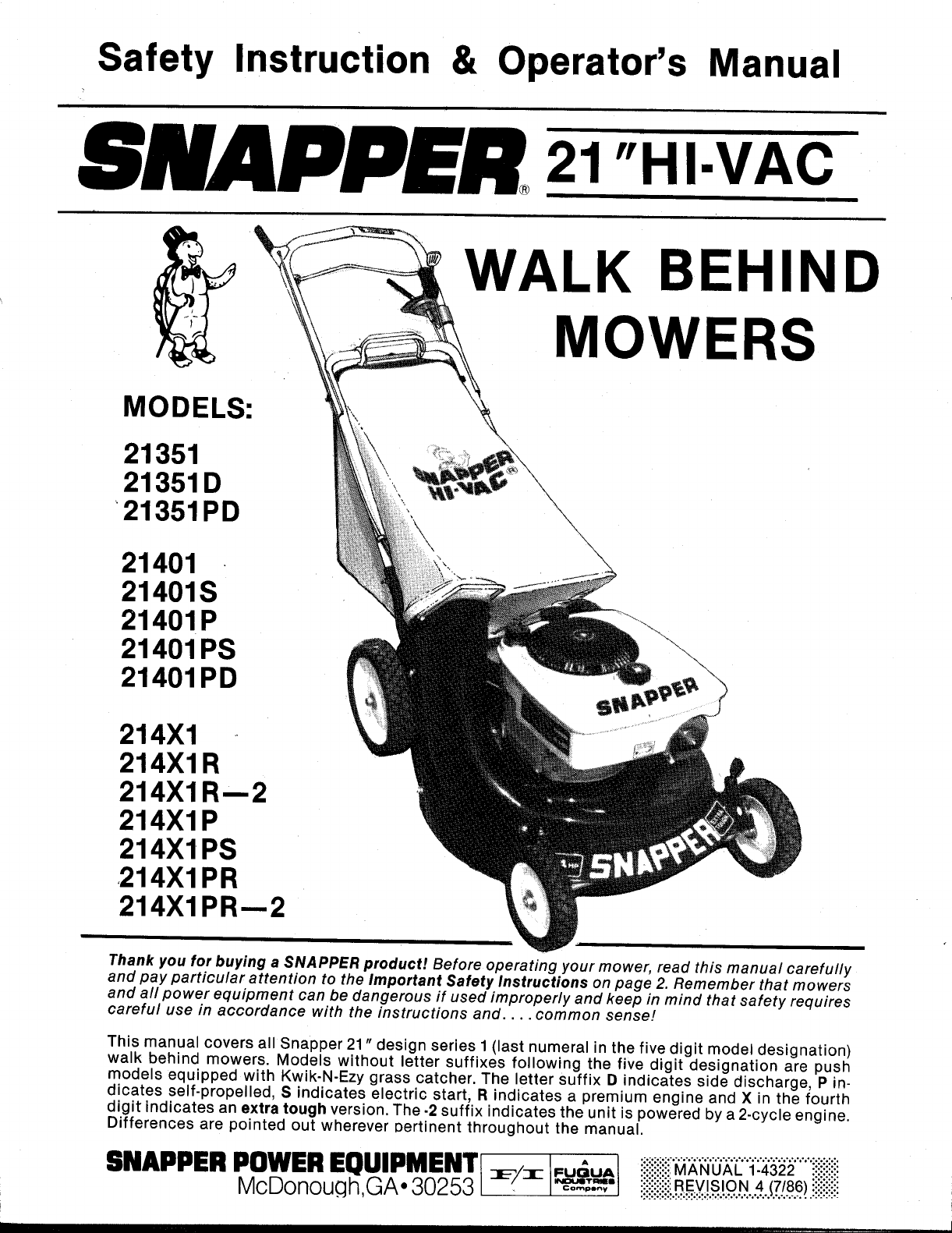
8NAPPER "HI.VAC
I
WALK BEHIND
MOWERS
MODELS:
21351
21351D
_21351PD
21401
21401S
21401P
21401PS
21401PD
214X1
214XIR
214XIR--2
214XIP
214XIPS
214XIPR
214XIPR---2
Thank you for buying a SNAPPER product! Before operating your mower, read this manual carefully
and pay particular attention to the Important Safety Instructions on page 2. Remember that mowers
and all power equipment can be dangerous if used improperly and keep in mind that safety requires
careful use in accordance with the instructions and .... common sense!
This manual covers all Snapper 21" design series I (last numeral in the five digit model designation)
walk behind mowers. Models without letter suffixes following the five digit designation are push
models equipped with Kwik-N-Ezy grass catcher. The letter suffix D indicates side discharge, P in-
dicates self-propelled, S indicates electric start, R indicates a premium engine and X in the fourth
digit indicates an extra tough version. The -2 suffix indicates the unit is powered by a 2-cycle engine.
Differences are pointed out wherever pertinent throughout the manual.
SNAPPER POWEREQUIPMENT[:_/-.-I..=;_. _:_:_i_i_i:i_____,""i:___"""ii::ii::iii!
McDonouqh GA 30253 / _oo-_J_o:o-,-::!::!::!::i::iiiREV_S_ON417/86)iiiiii!i:_
• ...:.:,:...:.:.,;:;:;:;:;.;t,;.;1.1...0.........,..-.-.-.-.-.........-.-
Page 2
IMPORTANT SAFETY INSTRUCTIONS
WARNING: Failure to comply with the following instructions may result in serious injury to the operator or other
persons. The owner of the mower must understand these instructions and, furthermore, must allow only persons
who understand these instructions to operate the mower. Each person operating the mower must be of sound
mind and body and must not be under the influence of any substance which might impair vision, dexterity, or
judgement. If you have any questions pertaining to your mower which your dealer cannot answer to your satisfac-
tion, call or write the Customer Service Department at SNAPPER POWER EQUIPMENT, McDonough
Georgia,30253. (Phone 404-957-9141).
TRAINING OPERATION
1.
Read this Manual carefully and question your dealer 1.
if something is not clear. Should the dealer be
unavailable or unable to answer to your satisfaction,
write or call our Customer Service Department at the 2.
factory. Be thoroughly familiar with the controls and
proper use of the equipment.
2. DO NOT allow children in yard when mower is
operated.
Do not change engine governor settings or overspeed
engine.
Do not put hands or feet near or under rotating parts.
Keep clear of discharge area while engine is running.
,
Stop engine when crossing gravel drives, walks, or
roads, and under any conditions where thrown ob.
jects might be a hazard.
3. DO NOT allow pre-teenager children to operate 4.
mower.
4,
Only responsible teenagers with mature judgement
shall be allowed to operate mower and only under
close supervision.
5,
Keep the area clear of all persons, particularly small
children, and pets.
PREPARATION 6.
1,
Never operate mower without proper guards, plates,
safety switches, or other safety protective devices in
place and properly connected. Inspect to determine
that these safety devices are installed properly, are
in good repair, and operate properly. If the condition
or operation of these devices are questionable, they
must be repaired or replaced before using the mower.
2.
Thoroughly inspect the area where the mower is to
be used and remove all stones, sticks, wire, bones
and other foreign objects. Also note the location of
holes, stumps, and other possible hazards.
3,
Do not operate mower when barefoot or wearing
open sandals. Always wear substantial footwear and
long pants.
4,
Fill gasoline tank before starting engine. Use approv-
ed gasoline container. Do not smoke near open
gasoline container. Do not fill gasoline tank indoors
or when engine is running. Allow engine to cool for at
least ten minutes before refilling. Wipe off any spill-
ed gasoline before starting engine. Do not run engine
indoors.
5, Make sure that the traction drive clutch control is
disengaged before starting engine.
6,
Never attempt to make a wheel height adjustment
while the engine is running.
After striking a foreign object or if mower vibrates ab-
normally, stop the engine, disconnect and secure
spark plug wire. Inspect the mower for any damage
and repair the damage.
5,
Stop engine whenever you leave the operating posi.
tion behind the handle for any reason, including emp.
tying grass bag and making any adjustments,
repairs, or inspections.
Before cleaning, repairing or inspecting, make cer-
tain blade and all moving parts have stopped.
Disconnect and secure spark plug wire away from
plug to prevent accidental starting.
7,
Stop engine and wait until the blade comes to com.
plete stop before removing grass bag andlor unclogg-
ing adapter.
8,
Mow across steep slopes, never up.and.down. Exer-
cise caution when changing directions on slopes. Do
not mow excessively steep slopes.
MAINTENANCE AND STORAGE
1,
Keep all nuts, bolts, and screws tight to be sure
mower, is in safe operating condition.
2,
Never store mower with gasoline in the tank inside of
a building where fumes may reach an open flame or
spark. Allow engine to cool before storing in any
enclosure.
3,
To reduce fire hazard, keep mower free of grass,
leaves or excessive grease.
4,
Check grass bag assembly frequently for wear or
deterioration. Replace with new bag if loose seams
or tears are evident. Replace slider or bag adapter if
broken or cracked.
7,
When mowing over rough ground or in tall grass,
mower must be set in highest cutting position.
8,
Mow only in daylight or in good artificial light.
.
Never operate mower in wet grass. Always be sure of
your footing; keep a firm hold on the handle and walk;
never run.
-2-
5.
Have your mower inspected and serviced each year
by an authorized Snapper dealer. Determine if any
additional devices are available which might upgrade
the safety of your mower.
,
Factory specified Snapper replacement parts must
be used to assure adequate protection against in-
jury.
Page 3
PRE-START CHECKS
Before each start-up, check the following and/or perform
the service specified as needed.
• CHECK guards, grass bag and adapter or side discharge
chute to make sure these items are in proper position and
securely tightened. NOTE: The tab on inside rear edge of
the adapter or side chute must push the interlock spring in
toward the center of the mower. If improperly installed, the
engine cannot be started.
oCLEAN surfaces to remove dust, dirt, clippings par-
ticularly from cooling air intake screen on engine to pre-
vent overheating.
• CHECK oil level in 4-cycle engine and add oil as needed
to bring the level up to, but not over, full mark.*
• CHECK cutting height and adjust, as needed, to suit
prevailing grass conditions before starting(Refer to height
adjusting procedure on page 4).
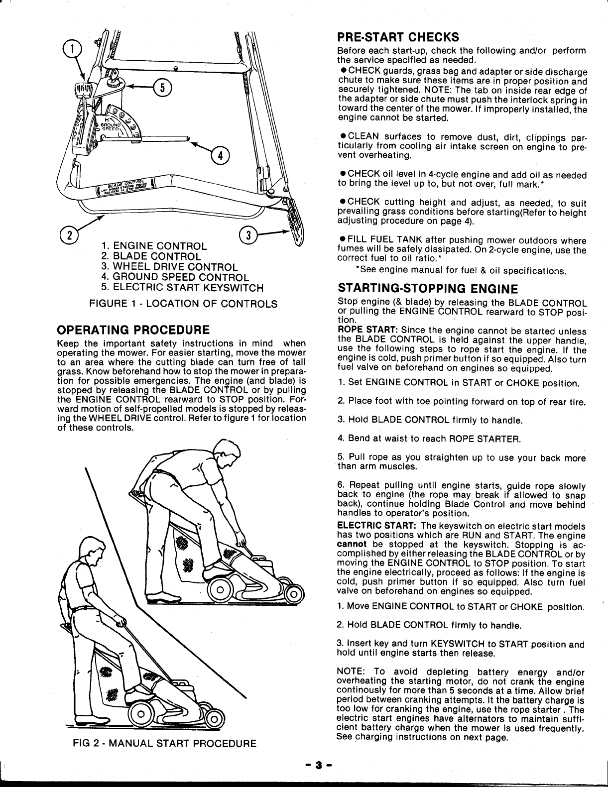
(_1. ENGINE CONTROL
2. BLADE CONTROL
3. WHEEL DRIVE CONTROL
4. GROUND SPEED CONTROL
5. ELECTRIC START KEYSWlTCH
FIGURE 1 - LOCATION OF CONTROLS
OPERATING PROCEDURE
Keep the important safety instructions in mind when
operating the mower. For easier starting, move the mower
to an area where the cutting blade can turn free of tall
grass. Know beforehand how to stop the mower in prepara-
tion for possible emergencies. The engine (and blade) is
stopped by releasing the BLADE CONTROL or by pulling
the ENGINE CONTROL rearward to STOP position. For-
ward motion of self.propelled models is stopped by releas-
ing the WHEEL DRIVE control. Refer to figure 1 for location
of these controls.
• FILL FUEL TANK after pushing mower outdoors where
fumes will be safely dissipated. On 2-cycle engine, use the
correct fuel to oil ratio.*
*See engine manual for fuel & oil specifications.
STARTING-STOPPING ENGINE
Stop engine (& blade) by releasing the BLADE CONTROL
or pulling the ENGINE CONTROL rearward to STOP posi-
tion.
ROPE START: Since the engine cannot be started unless
the BLADE CONTROL is held against the upper handle,
use the following steps to rope start the engine. If the
engine is cold, push primer button if so equipped. Also turn
fuel valve on beforehand on engines so equipped.
1. Set ENGINE CONTROL in START or CHOKE position.
2. Place foot with toe pointing forward on top of rear tire.
3. Hold BLADE CONTROL firmly to handle.
4. Bend at waist to reach ROPE STARTER.
5. Pull rope as you straighten up to use your back more
than arm muscles.
6. Repeat pulling until engine starts, guide rope slowly
back to engine (the rope may break if allowed to snap
back), continue holding Blade Control and move behind
handles to operator's position.
ELECTRIC START: The keyswitch on electric start models
has two positions which are RUN and START. The engine
cannot be stopped at the keyswitch. Stopping is ac-
complished by either releasing the BLADE CONTROL or by
moving the ENGINE CONTROL to STOP position. To start
the engine electrically, proceed as follows: If the engine is
cold, push primer button if so equipped. Also turn fuel
valve on beforehand on engines so equipped.
1. Move ENGINE CONTROL to START or CHOKE position.
FIG 2 - MANUAL START PROCEDURE
2. Hold BLADE CONTROL firmly to handle.
3. Insert key and turn KEYSWITCH to START position and
hold until engine starts then release.
NOTE: To avoid depleting battery energy and/or
overheating the starting motor, do not crank the engine
continously for more than 5 seconds at a time. Allow brief
period between cranking attempts. It the battery charge is
too low for cranking the engine, use the rope starter. The
electric start engines have alternators to maintain suffi-
cient battery charge when the mower is used frequently.
See charging instructions on next page.
-3-
Page 4

BATTERY CHARGING:A plug in battery charger is provided
which operates off 120V/60hz household current. When
recharging, disconnect battery from wiring harness, install
charger in household outlet and connect battery to
charger. If battery is weak charge for 48 hours. Charge bat-
tery for 72 hours if completely discharged.
Note: Continuous Charging will not damage battery.
MOWING PROCEDURE
Vary speed to suit grass conditions. Set the engine speed
high for tall, thick grass or lower for sparse grass. Push
hand propelled models at a speed that is comfortable but
will allow even cutting without stalling. On self propelled
models, set ground SPEED CONTROL lever in desired for-
ward speed setting, then grip the WHEEL DRIVE control
and hold against handle to engage clutch for forward mo-
tion. Releasing the WHEEL DRIVE control stops forward
motion. The mower can be hand pushed forward or in
reverse for trimming with the WHEEL DRIVE control
released. The ground speed can be changed to a new set-
ting at any time when in motion. Use low speed setting and
clutch for down-hill braking.
MOWINGIVACUUMING HINTS: The cutting deck should be
level under all conditions. As a general rule, never cut more
than 1/3 off the height of the grass. If for example, the
grass has grown to 4 inches tall, set the mower height lat-
ches in the lowest position which establishes the cutting
height at approximately 3" (see cutting height chart)
thereby, cutting about 718" off the grass and staying well
within the 1/3 off limit. If you want the grass shorter, wait a
few days then recut to the lower height. If cut too short, the
grass will expend more energy for development of new leaf
structures and less for a healthy root system and will be
more subject to burning. On the other hand, if allowed to
grow too long, the lower portion will be shaded and, as a
result will discolor. In dry periods, allow the grass to grow
longer than you normally would. NOTE: Do not mow across
an area where dry type fertilizer has just been spread as
most of the fertilizer will be vacuumed up.
Change your mowing pattern from time to time for a
smoother cut lawn. Finely chopped clippings add nutrients
to the soil to promote grass growth, however if the clipp-
ings become too heavy, they mat to form thatch which
prevents proper breathing and holds moisture. If thatch is
particularly heavy, the Thatcherizer accessory described
on the back page will do an effective job of dislodging the
decaying matter. To prevent grass disease from thatch,
vacuuming and bagging is recommended for most cut-
tings along with an occasional broadcasting of the clipp-
ings into the lawn for nutritive value. Your Snapper can be
quickly converted back and forth from bagging to side
discharge with the accessories.
EMPTYING GRASS CATCHER BAG
_ Highest
t
Cutting
Height
)
®
®
Position Q
®
ltll(l/
FIG. 3 - CUTTING HEIGHT SETTINGS
CUTTING HEIGHT ADJUSTMENT
Always stop the engine and wait until the mower blade
comes to a complete halt before readjusting the cutting
height! To readjust, move the height adjusting latch on
each wheel outward and slide each, one notch at a time, to
the position desired. Positioning the latches in the highest
notch sets the mower at the lowest cutting height while
the lowest notches sets it in the highest cutting position.
Refer to figure 3 for the approximate cutting height afford.
ed by each of the five latch positions: For best results, set
both latches on one side first, then go to the other side and
set these latches into corresponding notches. Before
resetting the rear latches into lower notches, lift the
weight of mower off'the rear wheels first by pulling up on
the handle, then reset.
To install the KWIK-N-EZY grass catcher on the mower,
slide the connector down over the adapter flange then
lower the support flame hooks onto the middle handle (see
figure 4). When the catcher becomes full, stop engine and
lift the support hooks up over the handle then lift the con-
nector off and continue lifting while moving the catcher
forward until the bagclears the mower. To empty the bag,
raise the connector end up and release the handle of the
door flap. Shake the catcher back and forth to dump the
clippings.
TO EMPTY IN TRASH BAG: Use the following procedure to empty
clippings in trash bag. After removing catcher from mower, place
connector erid on ground, open door flap, slip trash bag over the
catcher, turn catcher over so that large opening is down inside
bag, !ift catcher by connector and door handles and shake until
clippings are dUmped in the trash bag.
FIG. 4 - REMOVING GRASS CATCHER
m 4 _
Page 5

SERVICE PROCEDURE
The mower itself requires very little service, however, it is
important that the engine be serviced at the intervals
specified in the engine manual furnished with your mower.
When performing any services on the mower, always
disconnect the spark plug wire from the spark plug to pre-
vent unintentional starting. When tipping the mower to
work on the underside, always tilt with spark plug up to
prevent flooding the engine with gasoline and oil which
would cause hard starting after servicing. NOTE: On
Tecumseh powered units, comply with the following rules
to prevent oil from entering the air cleaner and ruining the
dry element (1) DO NOT keep engine in tilted position for
more than 5 minutes. (2) DO NOT crank engine or turn
blade while tilted (3) DO NOT tilt plug up more than 90
degrees.
To retain the quality of your mower, use Genui'ne Snapper
Replacement Parts only. To obtain the correct part for your
particular mower, always specify model and serial number
as found on nameplate. Contact your local Snapper Dealer
for parts and service assistance. We recommend returning
your mower to an authorized Snapper Dealer on a yearly
basis for inspection and addition of any new devices which
might upgrade the safety of your mower. For the nearest
Snapper Dealer, check the yellow pages under the heading
LAWN MOWERS.
LUBRICATION SERVICES
ENGINE- Change oil every 25 hours as specified in engine
manual.
TRANSMISSION(Self.Propelled Models). Remove plug and
check every 25 hours of operation. If grease is not visible
on the input gear, add small amount of Snapper "00"
grease, CAUTION: Avoid over lubricating, capacity not to
exceed 2 ounces of grease. Snapper "OO" grease is
available in a convenient quart size container (Part No.
1-1050) at your Snapper dealer. Replace plug after servic-
ing transmission.
MOVING PARTS - Occasionally put a few drops of oil on
movable surfaces of components such as the height ad-
justing levers, wheel axles, shift levers, etc. Be careful not
to spill oil on surface of drive disc on self-propelled
models.
CHECK FOR
GREASE ON
INPUT GEAR
' Fi(3. 5- CHECKING TRANSMISSION
\
CUTTING BLADE SERVICE
CAUTION: Before checking or doing any work on the blade,
disconnect the spark plug wire and secure it away from the
plug to prevent unintentional starting.
CHECK at frequent intervals to make sure the blade is
securely tightened and that it is in good condition.
REPLACE blade if badly chipped, bent, out of balance or
as soon as a notch starts wearing in the tip between the
flat surface and upturned lift as depicted in View B, Figure
6. This type wear pattern occurs more rapidly under sandy
soil conditions. CAUTION: Never operate the mower with
blade worn to the extent shown in View C as the tip could
fly off causing personal injury or property damage.
SHARPEN blade when the cutting edges become dull if the
blade is in otherwise good condition. Sharpen blade on a
grinding wheel at a angle of 22 to 28 degrees. The cutting
surface should extend in.about 31/2" from the tips. Check
the blade after sharpening to determine that it is still
balanced. It will cause excessive vibration if unbalanced.
BE CAREFUL: AVOID CUTTING YOURSELF ON SHARP
BLADE! Protect your hands from cuts while handling
blade
INSTALL blade with components in sequence shown in
Figure 7. Make sure that the turned-up rims in the center of
the blade fit over the edges of the blade drive hub when in-
stalling. Do no substitute any components here. Tighten
the blade retaining capscrew 20 to 30 foot pounds torque
value.
-5-
FIG 6 - BLADE WEAR PATTERNS
1-_'_'1 _,_ -BLADE HUB
(ON E_GINE)
(_'_"_" S PEC IA L RETAINING
i
FIG 7- BLADI£ RETENTION DETAIL
CAPSCREW
DANGEROUS
Page 6

FIG 8 - cLuTcH LINKAGE ADJUSTMENT
1/8"-1/4
IN HIGHEST
SPEED SETTING
CO NNECTO R
NUT
i ll|
FIG 9 - DRIVEN DISC COMPONENTS
FIG 10 - UNHOOKING DRIVE SPRING
-\
INNER
SPRING
DRIVE
DISC
CLUTCH LIN KAG E (Self-Propelled)
Make sure the vinylcover remains over the spring(s)con-
necting the clutch pull rodto the clutch idler components
(see Figure 8). This not only keeps the spring clean but
preventsit from rubbing against and wearing a hole in the
grass bag on mowers so equipped.
ADJUSTMENTS: If excessive pressure is required to hold
the wheel drive clutch lever in the engaged or drive posi.
tion, the clutch pull rodsprings are probably out of adjust-
ment. This is checked with the engine stopped and the
clutch handle released. When properly adjusted there
should be 1/16" to 1/8" clearance between the inside hook
of the spring and inside eye of the push rod as shown in
Figure 8. To adjust, unhookand rotate the inner and outer
springs in opposite direction, rehookand check clearance.
Repeat this procedure until the clearance is correct. If the
wheel drive control does not snap back to disengage the
drive when the handle is released, check the clip holding
the pull rodto the handle bar for binding. Position this clip
about 5" from the upper handle and rotate to best position
to allow the rod to slide without interference.
DRIVEN DISC SERVICE
If the mower does not pull properly with the wheel drive
clutch engaged, check for the following: Grease on drive
disc causing slippage, broken or disconnected driven
assembly spring (see Figure 10), driven disc too worn to
contact the drive disc properly, driven disc out rof adjust-
merit.This condition could also be caused byworn belts. If
the belts are in good condition and the clutch is properly
adjusted, service the drive system as follows:
DRIVEN DISC ADJUSTMENT: With the engine stopped and
the speed lever shifted into highest speed setting, the
driven disc should be 1/8" to 1/4" from the center of the
drive disc as illustrated in Figure 9. Readjust with engine
stopped as follows: Shift the speed selector into the
highest speed setting, loosen the connector hex nut and
slide the driven disc assembly inward or outward until the
center is 1/8" to 1/4" from the edge of the drive disc.
Retighten connector nut to lock at new setting.
DRIVEN DISC REPLACEMENT: If the rubberof driven disc
is badlychunked or worn downto within 1/16" of the metal
rim, remove the driven, disc assembly and replace the
driven disc as follows: Remove the clip and detach the
transfer rod from the speed control lever(Figure 10),Using
a pair of needle nose pliers, unhook the drive spring and
slide the driven disc assembly off as shown in Figure 11 .
Remove the five machine screws securing the rubber
driven disc and separate the worn disc from the hub.
Reversethis procedureto install the replacement disc and
to reconnect the drivecomponents.
BEARING REPLACEMENT: If the bearing fails, remove the
driven disc assembly as described above and replace the
bearing as follows: Remove the snap ring using special
snap ring pliers. Slide the driven ring, hub and bushing out
of the bearing. Remove the four screws and bearing.
Reverse this procedure to install the replacement bearing
and reconnect the drive components.
BELT SERVICE
Slippage of worn belts will cause self-propelled models to
pull poorly. On these the engine belt transmits this power
to the poly-V-belt which, in turn, engages the clutch to
drive the transmission and rear drive wheels.
ENGINE BELT REPLACEMENT: Disconnect the spark plug
wire and empty the fuel tank or tape the vents in the filler
cap to prevent fuel spillage then proceed as follows:
Unhook the idler arm spring from the right rear wheel
bracket and remove the driven dic assembly as described
under DRIVEN DISC service. Tilt the mower up on its right
wheels and removethe cutting blade and hub,then remove
the drive disc retaining nut and internal tooth Iockwasher.
Lift the drive disc-idler assembly off the deck and remove
faulty belt. Loopend of replacement belt over engine drive
-6-
Page 7

FIGURE 11 - SLIDING DRIVEN DISC ASSEMBLY OFF
POLY V-BELT
pulley and insert other end through deck opening. Loop
belt around driven pulley then push the drive, disc-idler
assembly down into position on the deck. Install the inter-
nal tooth Iockwasher and disc retaining nut on the drive
disc stud and securely tighten these. Test to make sure the
idler arm is free to pivot without interference then reinstall
the cutting blade components (refer to BLADE SERVICE),
driven disc assembly, then using a stiff wire(Hint: coat
hanger) with hooked end, pull the hooked end of the idler
arm spring through the larger hole in the right wheel
bracket and hook the end through the smaller hole.
POLY V-BELT REPLACEMENT:This belt can be replaced
after removing the driven disc assembly as described
earlier. Note the arrangement of old belt around pulleys
before cutting and removing it. Slip the replacement belt
over the end of hex shaft pulley and work over idler pulley.
Twist the belt sideways and pull it upward between the dif-
ferential bracket and transmission pulley. Slip belt over
grooves in the hex shaft, clutch idler and transmission
pulleys. Note: When properly installed, the lower span of
the Poly V-Belt will be above the belt guide.
RIGHT REAR \
WHEEL BRACKE'f
IDLER
IDLER
STORAGE PROCEDURE
Prepare your mower for Storage at the end of the mowing
season as follows. (Refer to the engine manual for direc-
tions for preserving engine). With the spark plug wire
disconnected, turn the mower on its side and thorougly
clean underside of deck. Scrape away grass with putty
knife and/or wire brush then wash down with water from a
hose. WARNING: Tape openings closed to prevent spray-
ing water into exhaust or air intake while washing. Clean
external surfaces of mower and allow to dry, then lubricate
all exposed metal with a light coating of oil to prevent cor-
rosion. Make sure grass bag is completely emptied to pre-
vent decay and formation of mold while in storage. The
grass bag may be washed in detergent but allow it to dry
thoroughly. Store mower during off season in a storage sh-
ed or dry area protected from weather. Handles on push
models can be tilted forward for storage by loosening
wingnuts--do not kink cables!
HANDLE HEIGHT ADJUSTMENT
To raise or lower handle, loosen tl_e adjusting Iocknuts on
both sides as shown below, reset handle to desired posi-
tion and retighten the Iocknuts.
LOOSEN
PUSH MODELS
ONLY
ON LOCKNUTS
\\
LEFT ,,,,
SIDE , ,_,....., ,
SHOWN ' / ' "
/t
/ POINT
/
CARRIAGE
__ X PIVOT
\ /
\ /
BOLTS FLAT WASHER
FIG. 13- HANDLE HEIGHT ADJUSTMENT
- 7 - (OVER) ,
Page 8

SNAPPER 21" HI-VAC WALK MOWERS
POPULAR ACCESSORIES
Depending on how your mower is originally equipped, it MULCHERIZER
can I_e converted to perform other lawn care duties with KIT #6-0420
the kits described below.
SNAPPERIZER KIT: Converts mower into an outdoor
vacuum and shredder to broadcast shredded clippings and
leaves with side discharge chute or for bagging with the
grass catcher. Specify model mower when ordering.
SNAPPERIZER
KIT #6-0440
MULCHERIZER KIT: Converts mower into effective mower
/mulcher to cut and chop the grass before blowing clipp-
ings directly into the lawn as nutritive mulch. Specify
model when ordering.
THATCHERIZER KIT: Attaches to front of self*propelled
models to dislodge thatch for vacuuming into grass cat-
cher. One kit fits all. 21" models.
GRASS CATCHER BAG KIT: If your mower is equipped
with side discharge chute, it can be converted for bagging
operation whenever desired with a grass bag kit. Specify
model when ordering.
SIDE CHUTE KIT: If your mower is equipped with the grass
catcher, it can be quickly converted to side discharge with
a side chute kit to broadcast clippings and eliminate bagg-
ing whenever desired, and to quickly convert back to bagg-
ing operation. Specify model when ordering.
THATCHERIZER
KIT #6-0476
'MANUFACTURER'S 2 YEAR LIMITED WARRANTY
For two (2) Years from purchase date for the original purchaser's residential, non-commercial use
[ninety (90) days from purchase date for the original purchaser's commercial, rental, or other non-
residential use], SNAPPER POWER EQUIPMENT, through any SNAPPER dealer will replace, free of
charge, any part or parts found upon examination by the factory at McDonough, Georgia, to be
defective in material or workmanship or both.
All transportation cost incurred by the purchaser in submitting material to a SNAPPER dealer for
replacement under this warranty must be borne by the purchaser.
This warranty does not apply to engines and their components, as these items are warranted
separately by their manufacturers, and does not apply to batteries which are covered separately.
This warranty does not apply to parts that have been damaged by accident, alteration, abuse,
improper lubrication, normal wear, or other cause beyond our control.
There is no other express warranty.
Implied warranties, including those of merchantability and fitness for a particular purpose, are
limite d to two (2) years from purchase date for the original pu_'chaser's residential, non-commercial
use [ninety (90) days from purchase for the original purchaser's commercial, rental or other non-
residential use], and to the extent permitted by law any and all implied warranties are excluded. This
is the exclusive remedy. Liabilities for consequential damages, under any and all warranties are
excluded.
Some states do not allow limitations on how long an implied warranty lasts,or do not allow the ex-
clusion or limitation of incidental or consequential damages, so the above limitation or exclusion
may not apply to you.
This warranty gives you specific legal rights, and you may also have other rights which vary from
state to state.
WARNING: THE USE OF REPLACEMENT PARTS OTHER THAN GENUINE SNAPPER PARTS MAY
IMPAIR THE SAFETY OF SNAPPER PRODUCTS AND WILL VOID ANY LIABILITY AND
WARRANTY BY SNAPPER ASSOCIATED WITH THE USE OF SUCH PARTS,
IMPORTANT: Please fill out the attached SNAPPER Product Registration Card immediately and
mail to:
SNAPPER POWEREQUIPMENT
MANUAL 1-4322 REV. 4 (7/86) McDonough, Georgia 30253 Printed in U.S.A.
 Loading...