

Page 1

Model 130.887660
Mid
Mfg. No.
1695735
Frame Snow Thrower
Description
Dual Stage Snow Thrower, 13.5 TP, 29 inch
1738348
Revision B
10/2009
Page 2

Thankyoufor purchasingthis quality-built Snappersnowthrower. We're pleasedthat you've placedyour confidencein the Snapper
brand. Whenoperatedand maintained according to the instructions in this manual,your Snapperproduct will provide many years of de-
pendableservice.
Thismanualcontainssafety information to makeyou awareof the hazardsand risksassociatedwith snow throwers and how to avoid
them. This snow thrower is designed and intendedonly for snow throwing and is not intendedfor any other purpose, it is important that
you readand understandtheseinstructions throroughly beforeattempting to start or operatethis equipment. Thissnow thrower
requires final assembly beforeuse, Referto the Quck Start Guidefor instructions on final assemblyprocedures.Follow the instructions
completely.Savethese instructionsfor future reference.
Product identificationTag
Product Identification Tag
Model Description Name/Number
Ill IIIIIII IIiil lllll Ilill lllll
Model / Modele/ Model ЧЧЧЧЧЧЧЧ
Unit MFG Number
Unit SERIAL Number
III lllllil Ilill lllll Illll IIIIIIlill III
Serial/ Serie / Serie ЧЧЧЧЧЧЧЧЧЧ
Briggs & Stratton Power Products Group, L.L.C.
Milwaukee, WI 53201 USA
Mower Deck MFG Number
Dealer Name
Engine Make Engine Model
When contactingyourauthorized dealer for replacement
parts,service, or informationyou MUST have these numbers.
Engine Type/Spec Engine Code/Serial Number
Recordyour model name/number,manufacturer's identification
numbers, and engine serialnumbers in the space provided for
easyaccess.Thesenumbers can befound in the locations
shown.
The illustrated Parts List for this machinecan bedownloaded from www.snapper.corn. Pleaseprovide modeland serial number when
ordering replacement parts.
Mower Deck SERIAL Number
Date Purchased
Snapper Products
535 Macon St.
McDonough, GA30253
1-800-317-7833
snappencom
Page 3

TABLEOFCONTENTS
OPERATORSAFETY.................................................................................... 4
FEATURESANDCONTROLS.......................................................................... 10
OPERATION............................................................................................. 12
BEFOREOPERATINGSNOWTHROWER...................................................................................................12
OPERATETHESNOWTHROWER..............................................................................................................12
STOPTHESNOWTHROWER....................................................................................................................13
WHEELLOCKOUTPIN..............................................................................................................................13
DISCHARGECHUTEANDDEFLECTOR....................................................................................................13
CHECKTHEOIL(BEFORESTARTINGENGINE)........................................................................................14
FILLTHEFUELTANK................................................................................................................................14
STARTTHEENGINE..................................................................................................................................15
STOPTHEENGINE....................................................................................................................................16
CLEARA CLOGGEDDISCHARGECHUTE.................................................................................................17
OPERATINGTIPS......................................................................................................................................17
MAINTENANCE......................................................................................... 18
SERVICERECOMMENDATIONS...............................................................................................................18
LUBRICATEAUGERGEARBOX.................................................................................................................19
LUBRICATEAUGERSHAFTFITTINGS......................................................................................................19
LUBRICATECONTROLLEVERLINKAGE...................................................................................................19
LUBRICATEDISCHARGECHUTEANDDEFLECTOR.................................................................................19
ENGINEMAINTENANCE...........................................................................................................................20
CHANGETHESPARKPLUG......................................................................................................................21
ADJUSTSKIDHEIGHT..............................................................................................................................22
BELTADJUSTMENT..................................................................................................................................23
BELTGUIDEADJUSTMENT......................................................................................................................23
SPEEDCONTROLRODADJUSTMENT.....................................................................................................24
CHECKANDADJUSTTHECABLES..........................................................................................................24
AUGERCONTROLCABLEADJUSTMENT.................................................................................................24
TRACTIONCONTROLCABLEADJUSTMENT...........................................................................................25
CHUTEROTATIONMOTORADJUSTMENT...............................................................................................26
AUGERSHEARPINREPLACEMENT.........................................................................................................26
CHECKTHETIRES....................................................................................................................................27
STORAGE................................................................................................ 28
OFFSEASONSTORAGE............................................................................................................................28
LUBRICATEHEXSHAFTANDCHAINS.....................................................................................................28
REMOVEFROMSTORAGE........................................................................................................................28
TROUBLESHOOTING................................................................................... 29
WARRANTIES........................................................................................... 31
SPECIFICATIONS....................................................................................... 33
Page 4

OPERATORSAFETY
,t_ DAHGER- Amputation Hazard
The dischargechutecontainsa rotating
impeller tothrowsnow. Never clear or unclog
the dischargechutewith yourhands.Fingers
canquickly becomecaughtandtraumatic
amputation or severe lacerationwill result.
Alwaysusea clean-outtool to clear or unclog
the dischargechute.
DANGER
,, Hand contactwiththe rotating impeller insidethe discharge
chuteisthe mostcommoncauseof injury associated with
snowthrowers.
,, Thissnowthrower iscapable of amputating handsand feet,
and throwingobjects. Readand observeall the safety
instructionsin this manual. Failure to do so will result in
deathor serious injury.
SafetyAlert Symboland SignalWords
,&
Thesafety alert symbol _ andsignal word (DANGER,
WARNING,CAUTION,or NOTICE)is used to indicate the likeli-
hood and potential severity of personalinjuryand/or damage to
the product. In addition, a hazardsymbol may be used to
represent the type of hazard.
Hazard Symbols and Meanings
Safety Alert - Identifies safety informationabout
hazardsthat can result in personal injury.
Operator's Manual- Read and understand before
performingany activity or running snow thrower.
t_
Rotating Impeller
t i _L,,,;_. I
Rotating Auger
Never Reach into
Rotating Parts
Fire
Shock ToxicFumes
_ Rotating Gears
t_,_ Thrown Objects
• Keepa Safe
Distance from
SnowThrower
Explosion
,ll_ DANGERindicates a hazardwhich, if not avoided,will
result in death or serious injury.
_ ARNINGindicatesa hazardwhich, if not avoided, could
resultin death or serious injury.
,i_ CAUTIONindicates a hazardwhich, if not avoided,could
resultin minor or moderate injury.
NOTICEindicates a situation that couldresult in damage
to the product.
WARNING
U.S.A. Models: Certain componentsinthis productand its
related accessories containchemicalsknown tothe state of
of California to causecancer,birth defects, or other repro-
ductive harm. Wash handsafter handing.
Recommended
HotSurface
Shut off engine and remove sparkplug connector
beforeperformingmaintenance or repairwork.
EarProtection for
ExtendedUse
WARNING
U.S.A. Models: The engine exhaust from this productcon-
rainschemicalsknown to the State of California to cause
cancer,birthdefects, or other reproductiveharm.
WARNING
U.S.A. Models: Batteryposts,terminals, and relatedacces-
sories containlead and lead components- chemicalsknown
tothe State of California to causecancerand reproductive
harm. Wash hands after handing.
Page 5

OPERATORSAFETY
Control Symbols on Equipment
._ Fuel
]=p-_
On Off
J+J Choke 0ff
R1--
I' 1°"°"°°°
Stop
Slow
Fast
Forward
Neutral
Reverse
ElectricStart -
Engage(Down) &
Disengage (Up)
Engine- Run
Engine - Stop
Readthe Manual
DANGER
Read,understand,andfollowall theinstructionsonthe
snowthrowerandintheoperator'smanualbeforeoperating
thisunit.
Failuretoobservethesafetyinstructionsinthismanualwill
resultindeathorseriousinjury.
o Bethoroughlyfamiliarwith thecontrolsandtheproperuseofthesnow
thrower.
,, Makesureyouareproperlytrainedbeforeoperatingthesnowthrower.
,, Knowhowtostoptheunitanddisengagethecontrolsquickly.
,, Neverallowanyonetooperatethesnowthrowerwithoutproperinstruction.
,, Alwaysfollow theinstructionsin theoperator'smanual,ifthesnowthrower
will bestoredfor anextendedperiod.
,, Maintainor replacesafetyandinstructionlabelsasnecessary.
,, Neverattempttomakemajorrepairsonthesnowthrowerunlessyouhave
beenproperlytrained.Improperservicingofthesnowthrowercanresult
in hazardousoperation,equipmentdamage,andvoidingoftheproduct
warranty.
Discharge Chute
w
m_,a
TractionControl -
Engage(Down)
m
AugerClutch
[_ ischargeChute
(Left and Right)
I w
=_'-m
-dr
AugerControl -
Engage (Down)
Chute Deflector
(Up and Down)
Heated HandGrips
(High and Low)
DANGER
Dischargechutecontainsrotatingimpellertothrowsnow.
Neverclearorunclogthedischargechutewithyourhands.
Fingerscanquicklybecomecaughtintheimpeller.Always
useaclean-outtool.
Failureto observethesesafetyinstructionswill resultin
traumaticamputationorseverelaceration.
TOSAFELYCLEARACLOGGEDDISCHARGECHUTE
,_ DANGER:Handcontactwiththerotatingimpellerinsidethedischarge
chuteisthemostcommoncauseofinjuryassociatedwithsnow
throwers.Neveruseyourhandstocleanoutthedischargechute.
FOLLOWTHESEINSTRUCTIONS:
1.ShutOFFtheengine.
2.Wait10secondstobesuretheimpellerbladeshavestoppedrotating.
3.Alwaysuseaclean-outtool,notyourhands.
NOTE:Hotall control symbolsshown on this pagewill appear
onyoursnowthrower.See FEATURESANDCONTROLSsection
for theapplicablesymbols.
Easy-TurnTM TractionControl
Free-Hand Control
TM
Page 6
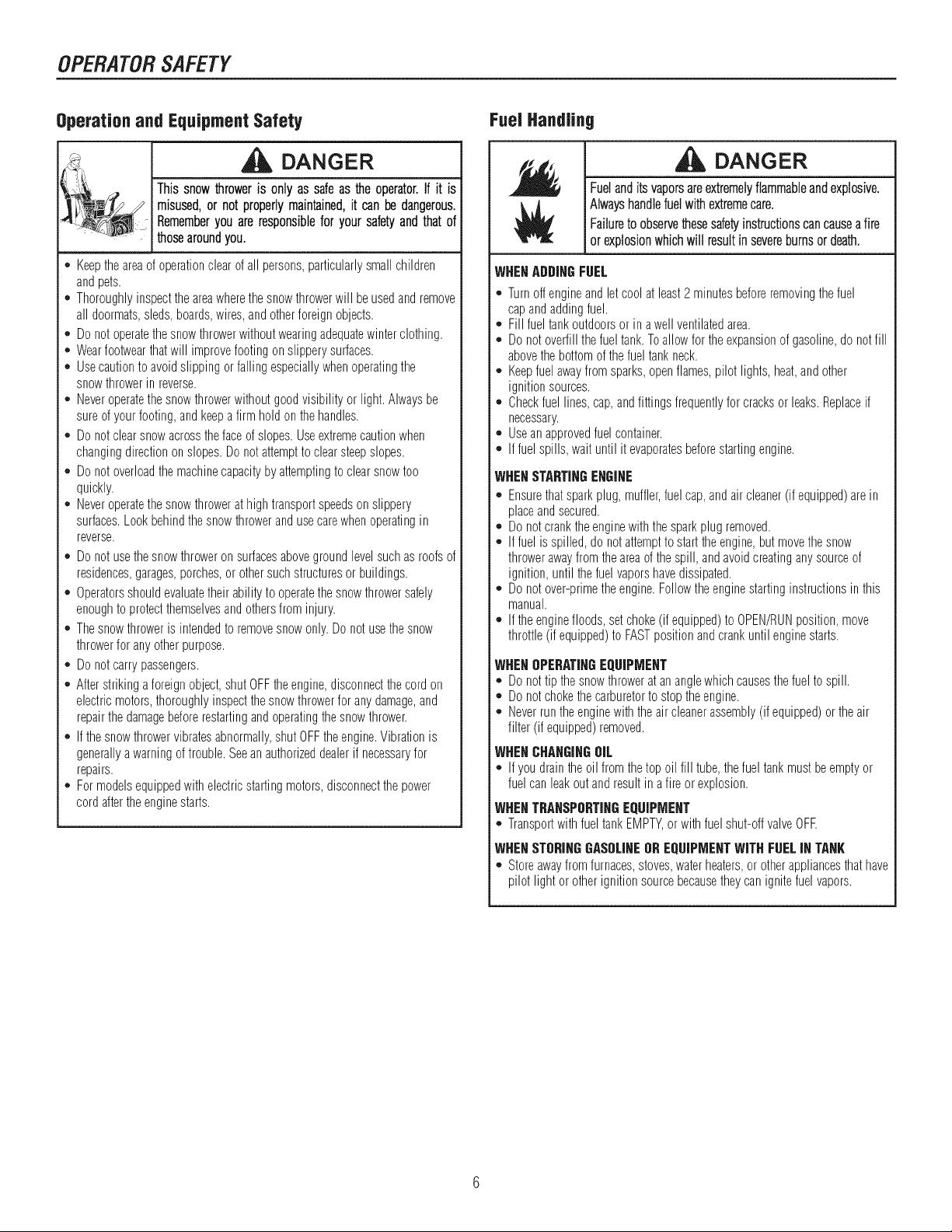
OPERATORSAFETY
Operationand EquipmentSafety
DANGER
Thissnowthroweris onlyassafeas theoperator.If it is
misused,or notproperlymaintained,it canbedangerous.
]Rememberyouareresponsibleforyoursafetyandthatof
thosearoundyou.
* Keeptheareaofoperationclearofall persons,particularlysmallchildren
andpets.
. Thoroughlyinspecttheareawherethesnowthrowerwill beusedandremove
all doormats,sleds,boards,wires,andotherforeignobjects.
. Do notoperatethesnowthrowerwithoutwearingadequatewinterclothing.
. Wearfootwearthatwill improvefootingonslipperysurfaces.
. Usecautiontoavoidslippingorfallingespeciallywhenoperatingthe
snowthrowerinreverse.
*, Neveroperatethesnowthrowerwithoutgoodvisibilityor light.Alwaysbe
sureof yourfooting,andkeepafirm holdon thehandles.
. Do notclearsnowacrossthefaceof slopes.Useextremecautionwhen
changingdirectiononslopes.Donotattemptto clearsteepslopes.
. Do notoverloadthemachinecapacitybyattemptingto clearsnowtoo
quickly.
. Neveroperatethesnowthrowerathightransportspeedsonslippery
surfaces.Lookbehindthesnowthrowerandusecarewhenoperatingin
reverse.
o Do notusethesnowthroweronsurfacesabovegroundlevelsuchasroofsof
residences,garages,porches,or othersuchstructuresorbuildings.
* Operatorsshouldevaluatetheirabilityto operatethesnowthrowersafely
enoughtoprotectthemselvesandothersfrominjury.
. Thesnowthrowerisintendedto removesnowonly.Donotusethesnow
throwerforanyotherpurpose.
. Do notcarrypassengers.
*, Afterstrikingaforeignobject,shutOFFtheengine,disconnectthecordon
electricmotors,thoroughlyinspectthesnowthrowerforanydamage,and
repairthedamagebeforerestartingandoperatingthesnowthrower.
*, If thesnowthrowervibratesabnormally,shutOFFtheengine.Vibrationis
generallyawarningof trouble.Seeanauthorizeddealerif necessaryfor
repairs.
. Formodelsequippedwithelectricstartingmotors,disconnectthepower
cordaftertheenginestarts.
FuelHandling
DANGER
Fuelanditsvaporsareextremelyflammableandexplosive,
Alwayshandlefuelwithextremecare.
Failuretoobservethesesafetyinstructionscancauseafire
Ior explosionwhichwill resultinsevereburnsordeath.
WHENADDINGFUEL
* Turnoffengineandletcoolat least2 minutesbeforeremovingthefuel
capandaddingfuel.
o Fill fueltankoutdoorsorin awellventilatedarea.
o Donotoverfillthefueltank.Toallowfortheexpansionof gasoline,donotfill
abovethebottomofthefueltankneck.
o Keepfuelawayfromsparks,openflames,pilotlights,heat,andother
ignitionsources.
o Checkfuellines,cap,andfittingsfrequentlyforcracksorleaks.Replaceif
necessary.
o Useanapprovedfuelcontainer.
o Iffuelspills,wait untilit evaporatesbeforestartingengine.
WHENSTARTINGENGINE
*, Ensurethatsparkplug,muffler,fuelcap,andair cleaner(if equipped)are in
placeandsecured.
. Donotcranktheenginewiththesparkplug removed.
. If fuelisspilled,do notattempttostarttheengine,butmovethesnow
throwerawayfromtheareaofthespill, andavoidcreatinganysourceof
ignition,until thefuelvaporshavedissipated.
*, Donotover-primetheengine.Followtheenginestartinginstructionsin this
manual.
. If theenginefloods,setchoke(if equipped)to OPEN/RUNposition,move
throttle(if equipped)to FASTpositionandcrankuntilenginestarts.
WHENOPERATINGEQUIPMENT
* Donottip thesnowthrowerat ananglewhichcausesthefuelto spill.
o Donotchokethecarburetorto stoptheengine.
o Neverruntheenginewiththeaircleanerassembly(ifequipped)or theair
filter (if equipped)removed.
WHENCHANGINGOiL
* If youdraintheoilfromthetopoil fill tube,thefueltankmustbeemptyor
fuelcanleakoutandresultin afire orexplosion.
IWHENTRANSPORTINGEQUIPMENT
*, TransportwithfueltankEMPTY,orwithfuelshut-offvalveOFE
I WNENSTORINGGASOLINEOREQUIPMENTWiTHFUELiN TANK
*, Storeawayfromfurnaces,stoves,waterheaters,or otherappliancesthathave
pilotlight or otherignitionsourcebecausetheycanignitefuelvapors.
Page 7

OPERATORSAFETY
Moving Parts
DANGER
Keephands,feet,andclothingawayfromrotatingparts.
Rotatingpartscancontactorentanglehands,feet,hair,
clothing,oraccessories.
Failuretoobservethesesafetyinstructionswillresultin
traumaticamputationorseverelaceration.
= Whenevercleaning,repairing,or inspectingthesnowthrower,makesurethe
engineisOFF,sparkplugwireisdisconnected,andallmovingpartshave
stopped.
. Donotputhandsorfeetnearor underrotatingparts.Keepclearofthe
dischargeopeningat alltimes.
. Neveroperatethesnowthrowerwithoutproperguards,andothersafety
devicesin placeandworking.
. Neverleavethesnowthrowerunattendedwhileengineis running.Always
disengagetheaugerandtractioncontrols,stopengine,andremovekeys.
. Keepall looseclothingawayfromthefrontofthesnowthrowerandauger.
Scarves,mittens,danglingdrawstrings,looseclothes,andpantscanquickly
becomecaughtin therotatingdeviceandamputationwill occur.Tieup
longhairandremovejewelry.
. Runthemachineafewminutesafterdischargingsnowtopreventfreeze-up
ofthecollector/impeller.
. Disengagepowertothecollector/impellerwhensnowthroweristransported
or notin use.
Thrown Objects
Children
DANGER
Tragicaccidentscanoccurif theoperatoris notalertto the
presenceofchildren,Childrenareoftenattractedto theunit
andtheoperatingactivity.Neverassumethatchildrenwill
remainwhereyoulastsawthem.
o Keepchildrenout oftheareaduringoperation.Childrenareoftenattractedto
theequipment.Bemindfulof all personspresent.
. Bealertandturnunit offif childrenenterthearea.
. Neverallowchildrento operatetheunit.
. Useextracarewhenapproachingblindcorners,shrubs,trees,or other
objectsthatmayobscurevision.Childrenmaybepresent.
Engine Safety
DANGER
_ and maintenanceoftheengine.Failureto observethesafety
I Safeoperationof thesnowthrowerrequiresthepropercare
instructionsin this manualwill result in deathor serious
injury.
. Disengageallclutchesandshiftintoneutralbeforestartingtheengine.
. Lettheengineadjustto outdoortemperaturesbeforestartingtoclearsnow.
. Useagroundedthree-wireplug-inforall snowthrowersequippedwith
electricdrivemotorsor electricstartingmotors.
DANGER
Objectscanbepickedupbyaugerandthrownfromchute.
Neverdischargesnowtowardbystandersorallowanyonein
frontofthesnowthrower.Failuretoobservethesesafety
instructionswillresultindeathorseriousinjury.
o Alwayswearsafetyglassesor eyeshieldswhileduringoperation,andwhile
performinganadjustmentor repair.
o Alwaysbeawareof thedirectionthesnowisbeingthrown.Nearby
pedestrians,pets,or propertymaybeharmedby objectsbeingthrown.
o Beawareofyourenvironmentwhileoperatingthesnowthrower.Running
overitemssuchas,gravel,doormats,newspapers,toys,androckshidden
undersnow,canall bethrownfromthechuteorjam intheauger.
o Useextremecautionwhenoperatingonor crossinggraveldrives,walks,or
roads.
o Adjustthecollectorhousingheighttocleargravelorcrushedrocksurface.
o Neveroperatethesnowthrowernearglassenclosures,automobiles,window
wells,drop-otis,andthelikewithoutproperadjustmentof thedischarge
chuteangle.
o Familiarizeyourselfwiththeareainwhichyouplanto operatethesnow
thrower.Markoffboundariesofwalkwaysanddriveways.
DANGER
Enginesgiveoffcarbonmonoxide,anodorless,colorless,
poisongas.
Breathingcarbonmonoxidecancausenausea,hinting,
or death.
* Startandrunengineoutdoors.
Donotruntheenginein anenclosedarea,evenif doorsorwindowsare
open.
Page 8

OPERATORSAFETY
Engine Safety (Continued)
WARNING
j Startingenginecreatessparking.
j Sparkingcanignitenearbyflammablegases.
Explosionandfirecouldresult.
* Ifthereisnaturalor LPgasleakagein area,donotstartengine.
,, Donotusepressurizedstartingfluidsbecausevaporsareflammable.
WARNING
,_l_((l(I}(_(ll,, Runningthe engineproducesheat.Enginepan, especially
i muffler,becomeextremelyhot.
Failureto observethesesafetyinstructionscouldresultin
i severethermalburnsoncontact.
* Nevertouchahotengineormuffler.Allow muffler,enginecylinder,andfins
to coolbeforetouching.
,, Removedebrisfrommufflerareaandcylinderarea.
,, Installandmaintaininworkingorderasparkarresterbeforeusingequipment
onforest-covered,grass-covered,orbrush-coveredunimprovedland.
,, U.S.A.Models:It isa violationof CaliforniaPublicResourceCode
Section4442to useor operatetheengineonor nearanyforest-covered,
brush-covered,orgrass-coveredlandunlesstheexhaustsystemis equipped
with asparkarrestermeetinganyapplicablelocalor statelaws.Otherstates
orfederalareasmayhavesimilarlaws.
Maintenanceand Storage
Thissnowthrowermustbeproperlymaintainedto ensuresafe
operationand performance.Failure to observethe safety
instructionsin this manualcould resultin deathor serious
injury.
* Whenperforminganymaintenanceor repairsonthesnowthrower,shutOFF
theengine,disconnectsparkplugwire,andkeepthewireawayfromthe
plugtopreventsomeonefromaccidentlystartingtheengine.
,, Checkshearboltsandotherhardwareatfrequentintervalsfor proper
tightnessto besurethesnowthrowerisin safeworkingcondition.
,, Keepnutsandboltstight andkeepsnowthrowerin goodcondition.
,, Nevertamperwithsafetydevices.Checktheirproperoperationregularlyand
makenecessaryrepairsiftheyarenotfunctioningproperly.
,, Componentsaresubjectto wear,damage,anddeterioration.Frequently
checkcomponentsandreplacewith recommendedparts,whennecessary.
,, Checkcontroloperationfrequently.Adjustandserviceasrequired.
,, Useonlyfactoryauthorizedreplacementpartswhenmakingrepairs.
,, Alwayscomplywithfactoryspecificationsonall settingsandadjustments.
,, Onlyauthorizedservicelocationsshouldbeutilizedfor majorserviceand
repairrequirements.
,, Useonlyattachmentsandaccessoriesapprovedby thefactory(suchas
wheelweights,counterweights,or cabs).
,, Neverattemptto makeanyadjustmentswhiletheengineis running(except
whenspecificallyrecommendedbythefactory).
WARNING
Page 9

OPERATORSAFETY
Lookfor this symboJto indicateimportantsafety
precautions.This symbolindicates:"Attention!
Become Alert! YourSafety isAt Risk."
Before operating yoursnow thrower, readthe safetydecals
as shownonyoursnowthrower.Thecautionsand warnings
are for yoursafety. Toavoid a personalinjuryor damageto
yoursnow thrower, understandand follow all the safety decals.
PartNo. 1738349
Shift Decal
Part No.1737870
TractionControlDecal
WARNING:Ifanysafetydecalsbecomewornordamagedand J
cannotberead,orderreplacementdecalsfromyourlocaldealer.
I
Part No.1737869
AugerControlDecal
EngineDecals
Part No.278297
_AMILY×XX××,X×XXX× X×XXX×
Part No.277953
ProductID Humber&
SerialHumberDecal
(Rearof Motor Box)
Amputation Hazard Risque d'amputation
• ceet_t wg_ a_ger wgz • xo_t contac_ _vec Ja
cause serious injury, t_ri_re provo_er_ de
• Keep hands, _eel and graves htassures.
clothing _way. * Tenir yes prods, yes mains
• Keep hyst_n_e_ _way. et vgteme.ts d Distance.
Thrown Objects Danger objets projet_g
Hazard •Ne lamtas dlflget ta
• Never dffect discharge o_e en di_ectta_ des
...........ch........ ds p...... _ _i!enlnPea__g,; en_sS.o. biens
Readthe operator's
m_n_al tar operattag and
safeIy taslructta_s. _eman_eJ d'_tg_safiolt.
Shut off engine and Arrg_er Je moleur et
remove hey before rotifer ta cta avast
.............perramming mataten_nce _ _2iiil°eiieng'eflect_e_tout e_ffettan
• Tenir tas spectateurs
Part No. 1737866
AugerDangerDecal
Part No. 1737875
Main DashDecal
Amputation hazard
Contact with m_ving pa_ts taside "_
chute wig cause serious tntury.
Shut off engine heto_e uncloggtag
discharge chute.
• Use clean-out tool not hands!
Risque d'amputation
Tout contact avec des pi_ces en mouvement _ r tat_deut
de la geulotta provoquera de graves b_esse_es.
• Arr_tar le _qotaur avant de d_gager Ja goulefle
d'djecttan.
• Utiliser Foutil de dggagement, gas les matas_
/Ji=
Part No. 1737865
ChuteDanger Decal
SafetyDecals
Figure
Page 10

FEATURESANDCONTROLS
NOTICE:ReadthisOPERATOR'SMANUALand OPERATORSAFETYbefore operatingyoursnowthrower. Comparethe illustrationswithyour
SNOWTHROWERto familiarize yourselfwiththe locationofvariouscontrolsand adjustments.Savethismanualfor future reference.
/
®
®
®
EngineControls Figure2
ENGINEANDSNOWTHROWERCONTROLS
ENGINECONTROLS
A. Choke Control Knob-- Usedto startacoldengine(seeFigure2).
B. ElectricStart Button-- Usedtostarttheengineusingtheelectric
starter.
C. Primer Button-- Usedto injectfueldirectlyintothecarburetor
manifoldto ensurefaststartsin coolweather.
D. Safety Key-- Mustbeinsertedtostartengine.Pullouttostop.Do
notturnsafetykey.
E. Starter CordHandle-- Usedtostarttheenginemanually.
F. ON/OFFSwitch-- Usedtostartandstoptheengine.
G. FuelTankand Cap-- Fillthefueltanktoapproximately1-1/2in.
(38mm)belowthetopofthenecktoallowforfuelexpansion.
H. 0il Fill Cap (Extended Dipstick)
SNOWTHROWERCONTROLS
A. SpeedSelect Lever-- Allowstheoperatortouseoneofsix(6)
forwardandtwo(2)reversespeeds(seeFigure3).Toshift,move
speedselectlevertodesiredposition.
NOTICE:Donot move speedselect lever while Traction
Control is engaged. This may resultin severe damage
tothe drivesystem.
10
Page 11

®
FEATURESANDCONTROL$
®
®
w
®
®
®
SnowThrowerControls
B. Auger Control Lever-- Usedtoengageanddisengagethe
augerandimpeller.Toengagepushdown,to disengagerelease.
C. Chute RotationSwitch-- Usedtorotatethedischargechute
totheleftor right.
D. Chute DeflectorSwitch-- Usedto controltheangleofthechute
deflector(upor down).
E. Free-HandTM Control -- Afterengagingthetractioncontrol(left
hand)andaugercontrol(righthand),allowstheoperatorto
releasetheaugercontrolleverto usetheothercontrols.
Figure3
F. TractionControlLever-- Usedtopropelsnowthrowerfor-
wardorreverse.Pushdowntoengage,releaseto disengage.
G. Clean-Out Tool -- Usedto removesnowanddebrisfromthedis-
chargechuteandthe augerhousing.
H Skid Shoe-- Usedto adjustthegroundclearanceof theauger
housing.
11
Page 12

OPERATION
BEFOREOPERATINGSNOWTHROWER
Checkthefasteners.Makesureallfastenersaretight.
Onelectricstartmodels,theunit wasshippedwith the startercord
pluggedintotheengine.Beforeoperating,unplugthestartercordfromthe
engine.
WARNING:The operation of any snow throwercan resultin foreign objects beingthrownintotheeyes, whichcanresultin
severe eye damage. Always wear safety glasses or eye shields before beginning snow throweroperation. We recommend
standard safety glasses or Wide Vision Safety Maskover spectacles.
OPERATETHE SNOW THROWER
dl_ CAUTION:Operation with a Snow Cab. Wind may blow
exhaust gasses backtowardsthe operator, ifyou notice
thesmell of exhaust, changedirection of operation.
NOTICE:Donot throwsnowtoward a buiJding as hiddenobjects
couldbe thrownwith sufficientforce to causedamage.
1. Starttheengine.See"ToStartEngine"inthis section. 5.
2. Pressthechuterotationswitch(A,Figure4)totheUP/DOWNposition
to rotatethedischargechuteleftorright.See"DischargeChuteand
Deflector"in thissection. 6.
3. Pushthechutedeflectorswitch(B)totheUP/DOWNpositionto
controltheangleof thechutedeflector.See"DischargeChuteand
Deflector"in thissection.
NOTE: This snow thrower was shipped WITH OiL in the
engine. See "Before Starting Engine" instructionsin the
OPERATIONsectionof this manuaJbefore startingengine.
CAUTION:Before operating, makesurethe area in
front of the snow throweris cJearof bystandersor
obstacJes.
4. Fullypressandholdtheaugercontrollever(C)toengageauger
rotation.Releasingtheaugercontrolleverwill disengagetheauger-
unlessthe Free-HandTM controlhasbeenactivated.
FullypressandholdthetractionandFree-HandTM controllever(D)to
engagethetractiondriveandbeginmovingthesnowthrower.Todis-
engagethetractiondrive,completelyreleasethelever.
WhenBOTHleversaredepressed,theFree-HandTM controlisacti-
vated.Thisallowsaugercontrollevertobereleased- YETAUGER
ROTATIONWILLCONTINUE- untiltheFree-HandTM controlisre-
leased.
Free-HandTM Control
Control Levers Figure4
NOTE:Always reJeasethetractioncontrollever before moving
thespeed select lever.
7. Usethespeedselectlever(E)toselecttheforwarddrivespeed.Setthe
speedselectleverto oneofthefollowingpositionsasdeterminedby
snowconditions:
1-2 Wet,Heavy,Slushy,ExtraDeep
3 Moderate
4-5 VeryLight
6 Transport
NOTE: Whenclearingwet, heavy,snow,it is recommended
thattheground speedof the unit bereduced,maintained fnlJ
throttleand donotattempt toclear thefuji widthof the unit.
8. Tostopmovingforward,releasethetractioncontrollever(D).
9. Tomovethesnowthrowerbackwards,movethespeedselectleverinto
eitherfirstorsecondreversepositionandengagethetractioncontrol
lever.
12
Page 13

OPERATION
STOPTHESHOWTHROWER
1. Releasetheaugercontrollever(C,Figure4).
2. Releasethetractioncontrollever(D).
3. PushtheON/OFFswitch(A, Figure12)totheOFFpositionandpull
outthesafetykey(B).
WARNING:Never run engine indoorsor in anenclosed,
poorventilatedarea. EngineexhaustcontainsCARBON
MONOXIDE,an ODORLESSand DEADLYGAS.
,, Keephands,feet, hair, and loose clothingaway
from any moving parts on engineand snow
thrower.
,, Temperatureof muffler and nearbyareas can
exceed150°F (66°C). Avoidthese areas.
,, DO NOTallow childrenor youngteenagers to
operate or be near snowthrower while it is
operating.
WHEELLOCKOUTKNOB
Eachwheelissecuredtotheaxlewitha lockoutpin.Theunitwasshipped
withthelockoutpin inthelockedposition.Foreaseofmaneuverability,
disconnectthelockoutpinasfollows.
1.Pulltheknob(A,Figure5)outtodisengagethelockoutpin.
WARNING:Read Operator's Manual before operating
machine.This machine can bedangerousif used
carelessly.
,, Never operatethe snowthrower without all guards,
covers, shields in place.
,, Never directdischargetowards windows or allow
bystandersnear machine while engine is
running.
,, Stopthe engine whenever leaving the operating
position.
• Disconnectspark plugbeforeunclogging the
impeller housingor the dischargechuteand
beforemaking repairsor adjustments.
,, Whenleaving the machine, remove thesafetykey.
Toreducetheriskof fire, keepthe machine clean
and free from spilledgas, oil, and debris.
2. Tolock in thedisengagedposition, turn the knob1/4 turn
(90degrees).
DISCHARGECHUTEANDDEFLECTOR
Discharge Chute Rotation (Left/Right)
1. PressthechuterotationswitchtotheUPpositionandholdtorotate
thechutetotheleft(A,Figure6).
2. Afterthedesiredpositionisobtained,releasetheswitchtotheCEN-
TERpositiontoturnoff.
3. PresstheswitchtotheDOWNpositionandholdto rotateclockwise.
ChuteDeflector(Up/Down)
1. Pressthechutedeflectorswitchto theUPpositionandholdto pro-
videa higherstreamandgreaterdistance(B,Figure6).
2. Afterthedesiredpositionisobtained,releasetheswitchtotheCEN-
TERpositiontoturnoff.
3. PresstheswitchtotheDOWNpositionandholdto providea lower
streamandlessdistance.
WheelLockout Knob
Figure5
DischargeChuteand Deflector Figure6
13
Page 14

OPERATION
CHECKTHE OiL (BEFORE STARTINGENGINE)
NOTE:Theenginewas shipped from thefactory filled with oil.
Checkthe level of the oil. Add oil as needed.
1.Makesuretheunit is level.Useahighqualitydetergentoil classified
"ForServiceSG,SH,SJ, SL,orhigher".
2. Removetheoilfillcap/dipstick(A,Figure7)andwipewithacleancloth.
3. Inserttheoilfillcap/dipstickandturnclockwisetotighten.
4. Removetheoilfillcap/dipstickandchecktheoil.
NOTE:Donot checkthe level of the oil while the engine runs.
5. If necessary,addoil untiltheoil reachestheFULLmarkontheoil fill
cap/dipstick.Donotaddtoomuchoil.
6. Tightentheoilfillcap/dipsticksecurelyeachtimeyouchecktheoil
level.
NOTE:Synthetic 5W30 motor oil is acceptable for all tempera-
tures. DONOTmix oil with gasoline. See Chartfor oil recom-
mendations.
oF
68 0
i 04
°C
5o
i 32
14
o4
°22
Below40°F(4°C)theuseofSAE30will resultin hardstarling.
** Above80°F (27°C)theuseof 10W-30maycauseincreasedoil consumption.Check
oil levelmorefrequently.
FULL
FiLL THE FUEL TANK
Thisengineis certifiedto operateongasoline.ExhaustEmissionControl
System:EM(EngineModifications).
Fillthefueltankwithfresh,clean,unleadedregular,unleadedpremium,orre-
formulatedautomotivegasolinewitha minimumof 85octanealongwitha
fuelstabilizer(followinstructionsonfuelstabilizerpackage).DONOTuse
leadedgasoline.Werecommendthatfuelstabilizerbeaddedtothefuel
eachtimethatgasolineisaddedtothefueltank.
NOTE:Winter grade gasoline has highervolatilityto improve
starting.Becertaincontaineris clean and free from rustor
other foreign particles. Never use gasoline that may bestale
from longperiodsof storagein the container.
_IL AUTION:DO NOTuse gasoline containingany
amountof alcohol as it cancauseseriousdamageto
the engineor significantlyreducethe performance.
Checkingthe Oil Figure7
,il_ WARNING:Gasolineis flammable.Always use
cautionwhenhandlingor storinggasoline. Turn
engineoff and letenginecoolat leasttwo minutesbefore
removingthe gascap. Donotadd gasolineto the fuel tank
whilesnow thrower is running,hot, orwhensnowthrower
isin an enclosedarea. Keepawayfrom open flame,
electricalsparks and DONOTSMOKEwhile filling the fuel
tank. Neverfill the fuel tank completely;but fill the fuel
tanktowithin1-1/2 inches(3.8 ram) fromthe top to
providespace for the expansionof the fuel. Alwaysfiii fuel
tankoutdoorsand use a funnelorspoutto preventspilling.
Makesureto wipe upany spilledfuel beforestartingthe
engine.
Storegasoline in a clean,approvedcontainer,and keep
thecapin placeonthe container.Keepgasoline in a cool
weftventilatedplace;neverinthe house.Never buymore
thana 30 daysupply of gasoline to assurevolatility.
Gasolineis intendedto be usedas a fuel for internal
combustionengines;therefore, do notusegasoline for any
other purpose.Since manychildrenlike the smell of
gasoline, keep it out of their reachbecausethe fumes are
dangeroustoinhale,as well asbeingexplosive.
14
Page 15

OPERATION
START THE ENGINE
BesurethatengineoilisatFULLmarkontheoilfill cap/dipstick.Thesnow
throwerengineisequippedwithanA.C.electricstarterandrecoilstarter.Before
startingtheengine,becertainthatyouhavereadthefollowinginformation.
Ifenginefloods,setthechoketotheOPEN/RUNpositionandcrankuntiltheen-
ginestarts.
,A_WARNING: Theelectricstarteris equippedwitha
three-wire powercordand plugdesignedto operateonAC
householdcurrent.Thepowercordmustbeproperly
groundedat all timesto avoidthe possibilityofelectricshock
whichcancauseinjurytothe operator.Followall instructions
carefullyassetforth:
Makesureyourhousehasa three=wiregroundedsystem.
Ifyouarenotsure,aska licensedelectrician.Ifyourhousedoes
nothaveathree-wire groundedsystem,do notusethiselectric
starterunderanycondition.
Ifyourhousehas athree-wire groundedsystembuta three-hole
receptacleisnotavailableto connectthe electricstarter,havea
three-holereceptacleinstalledbya licensedelectrician.
,_ WARNING:Toconnectpowercord, always connectthe
powercordfirst to the switch box located on the
engine and then plugthe otherend intoa three-hole
grounded receptacle.
,_ WARNING:Todisconnectthe power cord, always
unplugthe end connectedto the three-hole grounded
receptaclefirst.
Start the engineas follows:
1.Checktheoillevel.Seethe"Check/AddOil"sectionintheENGINE
MANUAL.
2. Makesureequipmentdrivecontrolsaredisengaged.
3. PushtheON/OFFswitch(A,Figure8)totheONposition.
4. Insertthesafetykey(A,Figure9) intothesafetykeyslotandpush
fullyin totheRUNposition.
5. Turnthechokeknob(B)fully clockwiseif engineiscold.
NOTE:Donot use the choke to starta warm engine.
6. Pushtheprimerbutton(C)twotimes.
NOTE:Donot usethe primerto start a warm engine.
NOTE:Ensurethat electric extension cordis removedfrom the
power receptacle.
InsertingSafetyKey Figure9
7.BewindStart:Firmlyholdthestartercordhandle(A,Figure10).Pull
thestartercordhandleslowlyuntilresistanceisfelt,thenpullrapidly.
,ll_ WARNING:Rapid retractionof the starter cord(kickback)
will pull your hand and armtoward the engine faster
than youcan let go. Brokenbones,fractures, bruises,
or sprainscouldresult. Whenstarting engine, pull the
starter cordslowly until resistanceisfelt and then pull
rapidlyto avoid kickback.
NOTE:If the engine does notstart after three attempts, see the
Engine Manual Troubleshootingsection.
8. ElectricStart: Firstconnecttheextensioncordtothepowercord
receptacleandthenintoawallreceptacle.Ifadditionalextensioncordis
required,makesureitis three-wire.
StartingtheEngine Figure8
_l_ WARNING:if the extension cordisdamaged, it must
bereplaced bythe manufacturer(or itsservice agent)
or a similarly qualified personto avoid a hazard.
15
Page 16

OPERATION
9. Electric Start:Depressthestarterpushbutton(A,Figure11).Afteryou
starttheengine,firstdisconnecttheextensioncordfromthewallreceptacle
andthenfromthepowercordreceptacle(B).
®
StartingwithElectricStart Figure11
StartingwithCordHandle Figure10
STOPTHEENGINE
Beforestoppingtheenginefor afewminutestohelpdryoffanymoisture
on theengine.
_ ARNING:Gasolineand vaporsare extremely
flammable and explosive. Fire or explosion can
causesevere burnsor death. DO NOTchokethe
carburetorto stopthe engine.
1.PushtheON/OFFswitch(A,Figure12)totheOFFposition.
2. Removethesafetykey(B).Keepthesafetykeyoutofthereachof
children.
IMPORTANT:Toextend the life of the starter, use short
startingcycles(five secondsmaximum). Wait one minute
between startingcycles.
NOTE:If the engine does notstartafter three attempts, see the
Engine Manual Troubleshootingsection.
NOTE:Donot lose the safety key. Keepthe safety key in a safe
place. The enginewill notstartwithoutthe safety/ignitionkey.
StoppingtheEngine Figure12
16
Page 17

OPERATION
CLEARA CLOGGEDDISCHARGECHUTE
_k ANGER:Handcontactwith the rotating impeJlerinside
the dischargechuteis the most commoncause of injury
associated with snowthrowers. Never dear or unclog
dischargechute with your hands, or while engine is
running.Fingerscan quickly becomecaught and
traumatic amputation or severe lacerationcan result.
_' SHUTOFFTHEENGINE!
,, Wait10secondsto besurethattheimpellerbladeshavestopped
rotating.
,' Alwaysusea clean-outtool,notyourhands.
A clean-outtool(A,Figure13)isattachedtoeitherthehandleorthetopofthe
augerhousing.Usetheclean-outtooltoremovesnowfromtheaugerhousing.
\\
\,\
\i
OPERATINGTiPS
1.Mostefficientsnowthrowingisaccomplishedwhensnowisremoved
immediatelyafteritfalls.
2. Forcompletesnowremoval,slightlyoverlapeachswathpreviouslytaken.
3. Snowshouldbedischargeddownwindwheneverpossible.
4. Fornormalusage,settheskids1/8inch(3 mm)belowthe scraper
bar.Forextremelyhard-packedsnowsurfaces,theskidsmaybead-
justedupwardto ensurecleaningefficiency.
5. Ongravelorcrushedrocksurfaces,theskidsshouldbesetat1-1/4
inch(32mm)belowthescraperbar(see"AdjustSkidHeight"inthe
MAINTENANCEsectionof this manual).Rocksandgravelmustnot
bepickedupandthrownbythemachine.
6. Afterthesnowthrowingjobhasbeencompleted,allowtheengineto
idleforafewminutes,tomeltsnowandiceaccumulatedonthe
engine.
7.Cleanthesnowthrowerthoroughlyaftereachuse.
8. Removeiceandsnowaccumulationandall debrisfromtheentire
snowthrower,andflushwithwater(if possible)toremoveall saltor
otherchemicals.Wipesnowthrowerdry.
9. Beforestartingsnowthrower,alwaysinspectaugersandimpellerfor
iceaccumulationand/ordebris,whichcouldresultin snowthrower
damage.
10.Checkoil levelbeforeeverystart.Makesurethe oil isattheFULL
markontheoil fill cap/dipstick.
Clean-OutTool
\\ \
Figure13
17
Page 18

MAINTENANCE
SERVICERECOMMENDATIONS
PROCEDURE 2 EACH EACH 5 10 25 EACH
Checkto MakeSure
AugerBladeStopsWithin
5 SecondsAfterRight ,/
SAFETY ControlLeveris Released
LubricateControlLevers ,/ ,/ ,/
andLinkages
CheckSnowThrowerfor
LooseHardware "/ '/
LubricateHexShaftand
Chains '/ '/
LubricateAugerShaft
Fittings ,/ ,/
SNOWTHROWER LubricateChuteRotation
GearandDeflector ,/
Mechanism
RemoveAll Snowand
SlushoffSnowThrowerto
PreventFreezingofAuger
or Controls
FIRST BEFORE AFTER EVERY EVERY EVERY BEGINNING
HOURS USE USE HOURS HOURS HOURS SEASON
v"
BEFORE
STORAGE
L_______ i i ,,,,, i
ENGINE
Oil,Check
OiI,Change ,/ ,/ ,/
¢ ¢ ¢
CheckandReplace
SparkPlug '/
NOTE:The warrantyon thissnowthrowerdoes not coveritems
thathavebeensubjectedto operator abuse or negligence.To
receivefull value from the warranty, operator mustmaintain
snowthrower as instructedinthis manual.
CheckTirePressure ,/
TheaboveService Recommendations aresuppliedto assisttheopera-
torto properlymaintainthesnowthrower.
18
Page 19

LUBRICATEAUGERGEARBOX
Theaugergearboxislubricatedatthefactoryandshouldnotrequire
additionallubrication,If forsomereasonthelubricantshouldleakout,
or if theaugergearboxhasbeenserviced,addLubriplateGR132Greaseor
equivalent.Maximum3-1/4ounces,(92grams)shouldbeused.
Removefiller plug(A,Figure14),onceayear.Ifgreaseis visible,donot
add.Ifgreaseis notvisible,useapieceoffinewire,likeadipstickto check
ifthereisgreaseinthegearbox.MobiluxEP1andShellAlvaniaEP1are
suitableequivalents.
MAINTENANCE
,,¢
LubricatingControlLeverLinkage Figure15
LUBRICATEDISCHARGECHUTEANDDEFLECTOR
Lubricatethechuterotationgear(A,Figure16)anddeflectorhinge(B)with
automotivetypeoileverytwenty-five(25)operatinghours.
LubricatingAugerGearBox Figure14
LUBRICATEAUGERSHAFTFITTINGS
1.Usingahandgreasegun,lubricatetheaugershaftfittings(B,Figure
14)everyten(10)operatinghours.Eachtimea shearpinis replaced,
theaugershaft(C)MUSTbegreased.(See"AugerShearPinReplace-
ment"section.)
2. Forstorageorwhenreplacingshearpins,removeshearpinsand
lubricateaugershaftfittings(B).Rotateaugersseveraltimesonthe
shaftandreinstalltheshearpins.
LUBRICATE CONTROL LEVER LINKAGE
CheckthefunctionoftheFree-Handcontrols.Thecontrolsshouldfunction
asdescribedin theOPERATIONsection.
,_ WARNING:It iscritical for the safe operation of the
unitthat the controlsdisengagewhen released.
Lubricatethelinkageforthetraction/Free-Handcontrol(A,Figure15),
speedselectcontrol(B),andaugercontrol(C)everyten(10)operating
hours,or asnecessaryto ensuresafeoperation.
NOTICE:Underno circumstancesshould the unit be usedif the
controlsdo notfunction properly.
LubricatingDischargeChuteandDeflector Figure16
19
Page 20

MAINTENANCE
ENGINEMAINTENANCE
CheckCrankcase Oil Level - Beforestartingengineandaftereach8
hoursofcontinuoususe.Addtherecommendedmotoroil asrequired.
NOTE:Over filling the engine can affect performance.Tighten
the oil fill cap securely to prevent leakage.
ChangeOil - Every50 hoursofoperationoratleastonceayear,evenif
thesnowthrowerisnotusedforfiftyhours.Useaclean,highquality
detergentoil.Fillthecrankcaseto FULLlineon dipstick(A,Figure17).Be
sureoriginalcontaineris marked:A.P.I.service"SF"orhigher.Donotuse
SAE10W40oil (asit maynotprovideproperlubrication).See Chart for
oil recommendations.
Drain Oil - Positionsnowthrowersothattheoil drainplug(A,Figure
18)is lowestpointonengine.Whentheengineiswarm,removeoil drain
plugandoil fill capanddrainoil intoasuitablecontainer.
Replaceoil drainplugandtightensecurely.Refillcrankcasewiththe rec-
ommendedmotoroil.
°C
Full
CheckingCrankcaseOil Level Figure17
-22
Below40°F(4°C)theuseofSAE30will resultin hardstarting.
** Above80°F (27°C)theuseof 10W-30maycauseincreasedoil consumption=Check
oil levelmorefrequently.
Oil DrainPlug Figure18
2O
Page 21

CHANGETHESPARKPLUG
Remove the Snow Hood
1.Removethechokecontrolknob(A,Figure19).
2. Removethesafetykey(B).
3. Removethemountingscrews(A,Figure20).
4. Slowlyremovethesnowhood(B)Makesurethattheprimerbutton
hose(C)andtheignitionwire(D)arenotdisconnected.
5. Thesparkplug(E)cannowbeaccessed.
6. Toinstallthesnowhood,firstmakesurethattheprimerbuttonhose
andtheignitionwireareconnected.
7.Mountthesnowhoodtotheengineandsecurewiththemounting
screws.
8. Connectthechokecontrolknob(A,Figure21)withthechokeshaft
onthecarburetor(B).Makesurethechokecontrolknobisproperly
installed.Ifthechokecontrolknobis notinstalledcorrectly,thechoke
will notoperate.
9. Installthesafetykey(C).
MAINTENANCE
RemovingtheSnowHood Figure20
SnowThrowerEngine Figure19
ConnectingChokeControlKnob Figure21
21
Page 22

MAINTENANCE
CheckandReplaceSparkPlug
Checkthesparkplugeverytwenty-five(25)hours.Replacethesparkplug
(Figure22)iftheelectrodesarepittedorburnedoriftheporcelainis
cracked.
1.Removesnowhood(see"RemovetheSnowHood"section).
2. Cleansparkplugandresetgapperiodically.
3. Cleanareaaroundsparkplugbasebeforeremoval,topreventdirt
fromenteringengine.
4. Replacesparkplugifelectrodesarepittedor burnedor if porcelainis
cracked.
5. Cleansparkplugbycarefullyscrapingelectrodes(donotsandblast
orusewirebrush).
6. Besuresparkplugis cleanandfreeofforeignmaterial.Checkelec-
trodesgapwithawirefeelergaugeandresetgapto0.030"(0.76ram)
if necessary.
7.Beforeinstallingsparkplug,coatthreadslightlywithgraphitegrease
toinsureeasyremoval.
8. Tightenplugfirmlyinto engine.Iftorquewrenchisavailable,tighten
plugto18-23ft-lbs(24.4-31.2Nm).
\
ReplacingSparkPlug Figure22
,_ WARNING:Alwaysturn unitoff, remove ignitionkey,
and disconnectthe sparkplugwire beforemakingany
repairs or adjustments.
ADJUSTSKiD HEIGHT
Thissnowthrowerisequippedwithtwoheightadjustskids,securedtothe
outsideoftheaugerhousing.Theseelevatethefrontofthesnowthrower.
Whenremovingsnowfromahardsurfaceareasuchasa paveddriveway
orwalk,adjusttheskidsupto bringthefrontofthesnowthrowerdown.
Whenremovingsnowfromrockor unevenconstruction,raisethefrontof
thesnowthrowerbymovingtheskidsdown.Thiswill helpto prevent
rocksandotherdebrisfrombeingpickedupandthrownbytheaugers.
Toadjustskids,proceedasfollows:
1.Placeablock(equalto heightfromgrounddesired)underscraperbar
nearbutnotunderskid.
2. Loosenskidmountingnuts(A, Figure23)andpushtheskid down
(B)untilittouchestheground.Retightenmountingnuts.
3. Setskidonothersideatsameheight.
NOTE:Make surethatsnowthroweris set at same heighton
both sides.
WARNING:Becertainto maintainproper ground
clearance for your particulararea to be cleared.
Objects suchas gravel, rocks, or other debris, if
struckbythe impeller, may bethrown withsufficient
force to cause personalinjury, propertydamage,or
damageto the snowthrower.
AdjustingSkidHeight Figure23
22
Page 23

BELTADJUSTMENT
TractionDriveBelt
Thetractiondrivebelthasconstantspringpressureanddoesnotrequire
anadjustment.Ifthetractiondrivebeltisslipping,replacethebelt.Seeau-
thorizeddealer.
AugerDriveBelt
Ifyoursnowthrowerwillnotdischargesnow,checkthecontrolcableadjust-
ment.Ifitiscorrect,thenchecktheconditionoftheaugerdrivebelt.Ifitis
damagedor loose,replaceit(seeauthorizeddealer).
1.Disconnectsparkplugwire.
2. Removescrew(A,Figure24)frombeltcover(B).Removebeltcover.
3. Loosennutonidlerdrivepulley(A,Figure25)andmoveidlerdrive
pulleytowardsbeltabout1/8inch(3 mm).
_ ARNING:Donot over-tighten, as this may lift the
lever and causethe auger driveto be engagedwithout
depressingthe auger control.
4. Tightennut.
5. Withtheaidofanassistant,engagetheaugerdriveclutch.Checkten-
sionon beltwhichisoppositeidlerpulley(B,Figure25).Beltshould
deflectabout1/2inch(12.5mm)withmoderatepressure.Youmay
havetomoveidlerpulleymorethanoncetoobtainthecorrectten-
sion.
6. Releasetheaugerdrivecontrollever.Theauger muststopwithin
5 seconds.
7.Ifaugerdoesnotoperateproperly,stopengineandrecheckdrive
linkageadjustments.
8. Reinstallbeltcover(B,Figure24).Tightenscrew(A).
9. Wheneverbeltsareadjustedor replaced,thecableswill needtobe
adjusted(see"CheckandAdjusttheCables"section).
10.Attachthesparkplugwire.
MAINTENANCE
AdjustingAugerDriveBelt Figure24
BELT GUIDE ADJUSTMENT
1.Removesparkplugwire.
2. Havesomeoneengagetheaugerdrive.Thiswillengageaugeridler
pulley(A,Figure26).
3. Measurethedistancebetweenthe beltguide(B)andbelt(C).The
distanceshouldbeabout1/8inch(3 ram).
4. Ifadjustmentisnecessary,loosenbeltguidemountingbolt.Move
beltguidetothecorrectposition.Tightenmountingbolt.
5. Installbeltcover.
6. Connectsparkplugwire.
CheckingTensiononAugerDriveBelt Figure25
1/8"(3mm)
®
AdjustingBeltDrive Figure26
23
Page 24

MAINTENANCE
SPEEDCONTROLRODADJUSTMENT
Ifthespeedcontrolrod(A,Figure27)requiresadjustment,seeanauthor-
izeddealerforassistance.
CHECKANDADJUSTTHECABLES
Thecablesareadjustedatthefactoryandnoadjustmentshouldbeneces-
sary.Ifthecableshavebecomestretchedoraresaggingadjustmentwillbe
necessary.
Wheneverbeltsareadjustedorreplaced,thecableswill needtobead-
justed.
AUGER CONTROL CABLE ADJUSTMENT
,_ WARNING:Do not over-tighten,as this may lift the
lever and causethe auger driveto be engagedwith-
out depressingtheauger drivecontrol.
1.Withtheaugerdrivecontrolleverreleased,thehook(A,Figure28)
shouldbarelytouchthelever(B)withoutraisingit.Therecanbea
maximumof 1/32"(0.8mm)clearance.
2. Toadjust,loosenthenut(C)by holdingtheadjustingflats(D)and
turningthenut.Then,turntheadjustingflatsandholdthe adjust-
mentscrew(E).Theadjustmentscrewis a phillipsscrewandthe
headcanbeheldorturnedbyinsertingascrewdriverthroughthe
spring(F).
3. Holdtheadjustingflatsandtightenthenut.
4. Starttheengineandchecktheauger.Theaugermustnotbeengaged
unlesstheaugerdrivecontrolleverisdepressed.
5. Withtheenginerunning,fully depresstheaugerdrivecontrollever.
Theaugershouldengageandrunnormally.
6. Releasetheaugerdrivecontrollever.Theaugermuststopwithin5
seconds.
7.Iftheaugerdoesnotoperateproperly,stoptheengineandrecheck
theaugerdrivecableadjustment.
8. Ifthedrivelinkageis properlyadjusted,thetensionof theaugerdrive
beltmayrequireanadjustment(see"BeltAdjustment"section).
AdjustingSpeedControlRod
AdjustingAugerControlCable
Figure27
Figure28
24
Page 25

TRACTIONCONTROLCABLEADJUSTMENT
1.Removethegasfromthegastank.Standthesnowthrowerupon the
frontendoftheaugerhousing.
or flame.
[_ ARNING:Drainthe gasoline outdoors, away from fire
2. Loosenthebolts(A,Figure29)on eachsideofthebottompanel(B).
3. Removethebottompanel.
4. Slidethecableboot(A,Figure30)offthecableadjustmentbracket
(B) I
5. Pushthebottomofthetractiondrivecable(C)throughthecable
adjustmentbracketuntilthe "Z"hook(D)canberemoved.
6. Removethe"Z"hookfromthecableadjustmentbracket.Movethe"Z"
hookdownto thenextadjustmenthole.
7.Pullthetractiondrivecableupthroughthecableadjustmentbracket.
81Putthecablebootoverthecableadjustmentbracketi
9. Tochecktheadjustment,depressthedriveleverandcheckthelength
ofthedrivespring(A,Figure31).Incorrectadjustment,thelength
ofthedrivespringis aminimum3 inches(76mm)anda maximum
3-3/8inches(85mm).
10.Installthebottompanel(B,Figure29)1
11.Tightenthebolts(A)oneachsideofthebottompanel.
TractionDriveCable
MAINTENANCE
Figure30
AdjustingTractionDriveCable Figure29
CheckingAdjustmentofTractionDriveCable Figure31
25
Page 26

MAINTENANCE
CHUTEROTATIONMOTORADJUSTMENT
Iftheelectricchuterotatordoesnotfunctionproperly,checktheelectrical
connectionsandthenperformtheprocedurebelow.
1. Removetherotatormotorcover.
2. Lubricatethechuteringgear.
3. Loosenthescrews(A,Figure32)securingtherotatormotorandad-
justsothatthemotorgearandchuteringgearmesh.Tightenthe
capscrews.
4. Reinstallthechuterotationcover.
AUGERSHEARPiNREPLACEMENT
Theaugersaresecuredtotheaugershaftwithspecialshearpinsthatare
designedto breakif anobjectbecomeslodgedintheaugerhousing.Use
of a hardergradeshearpinwill reducetheprotectionprovidedbythe
shearpin.
AdjustingChuteRotationMotor Figure32
,_WARNING: Donot go nearthe dischargechuteor auger
when the engine is running.Do notrunthe engine if
any coveror guardisremoved.
Undermostcircumstances,if theaugerstrikesanobjectwhichcould
causedamagetotheunit,theshearpinwill break.Thisprotectsthegear
boxandotherpartsfromdamage.
Theshearpins(AandB,Figure33)arelocatedontheaugershaft.Replace
abrokenshearpinasfollows.
1.Tapoutthebrokenshearpinwitha pinpunch.
2. Installanewshearpinandcotterpin.Bendtheendsofthecotterpin
down.
iMPORTANT:Do not replaceshearpinswithanything other
thanthe correctgradereplacement shearpin. Useof bolts,
screws,or hardergradeshearpins can result in equipment
damage.
ReplacingBrokenShearPin Figure33
26
Page 27

CHECKTHETIRES
Checktiresfor damage.Checktheair pressureinthetireswithan
accurategauge(seeFigure34).
_ AUTION:Avoidinjury! ExpJosiveseparationof tire
and rim parts is possible when theyare serviced
incorrectly.
= Donotattempt to mounta tire without theproper
equipment and experience to perform thejob.
= Donot inflatethetires above the recommendedpressure.
= Donotweld or heat a wheel and tire assembly. Heatcan
causean increase in air pressure resultingin an
explosion. Welding can structurallyweaken or deform the
wheel.
• Do not standin front or overthe tire assembly when
inflating. Useappropriate toolthat allows youto standto
one side.
NOTICE:Checkside of tirefor maximum tire pressure. DO
NOTexceed maximum.
MAINTENANCE
CheckingTire Air Pressure Figure34
27
Page 28

STORAGE
OFFSEASONSTORAGE
WARNING:Never storethe engine, withfuel in the tank,
,A
indoorsor in a poorventilated enclosurewhere fuel
fumes couldreachan openflame, sparkor pilot light
as on a furnace,water heater,clothesdryer,etc.
Handle gasoline carefully. It is highlyflammable and
carelessuse could resultin seriousfire damage toyour
personand/orproperty.
Drain fuel into approvedcontainersoutdoors, away from
open flame.
If thesnowthrowerwill bestoredforthirty(30)daysormoreattheendof
thesnowseason,thefollowingstepsarerecommendedto prepareyour
snowthrowerfor storage.
NOTE:Gasoline must be removedor treated to prevent gum
depositsfrom forming inthe tank, filter, hose,and carburetor
duringstorage.
1.Removegasoline,byrunningengineuntiltankisemptyandengine
stops.Ifyoudonotwantto removethegasoline,addfuelstabilizer
toanygasolineleftinthetankto minimizegumdepositsandacids.
Ifthetankisalmostempty,mixstabilizerwithfreshgasolinein a
separatecontainerandaddsomeofthemixturetothetank.ALWAYS
FOLLOWINSTRUCTIONSONSTABILIZERCONTAINER.THENRUN
ENGINEATLEAST10MINUTESAFTERSTABILIZERISADDEDTO
ALLOWMIXTURETOREACHCARBURETOR.STORESNOW
THROWERINSAFEPLACE.
2. Youcanhelpkeepyourengine(4-cyclesonly)in goodoperating
conditionby changingoil beforestorage.
3. Lubricatethepiston/cylinderarea.Thiscanbedonebyfirst removing
thesparkplugandsquirtingcleanengineoilintothesparkplughole.
Thencoverthesparkplugholewitharagto absorboil spray.Next,
rotatetheengineby pullingthestartertwoorthreetimes.Finally,
reinstallsparkplugandattachsparkplugwire.
4. Thoroughlycleanthesnowthrower.
5. Lubricateall lubricationpoints(see"Lubrication"topicsinthe
MAINTENANCEsection).
6. Makesureall nuts,bolts,andscrewsaresecurelyfastened.Inspect
allvisiblemovingpartsfordamage,breakage,andwear.Replaceif
necessary.
7.Touchupall rustedorchippedpaintsurfaces;sandlightlybefore
painting.
8. Coverthebaremetalpartsofthesnowthrowerhousingauger,and
theimpellerwithrustpreventative.
9. If possible,storeyoursnowthrowerindoorsandcoverittogive
protectionfromdustanddirt.
10.Onmodelswithfolding handles,loosentheknobsthatsecurethe
upperhandle.Rotatetheupperhandleback.
11.Ifthemachinemustbestoredoutdoors,blockupthesnowthrower
andensuretheentiremachineisofftheground.Coverthesnow
throwerwithaheavytarpaulin.
LUBRICATEHEXSHAFTANDCHAINS
CAUTION:Do not allow grease or oil tocontactthe
,&
rubberfrictionwheel or thediscdrive plate, if the
discdriveplate orfrictionwheel comein contactwith
greaseor oil damageto rubberfrictionwheel will
result.
NOTICE:If greaseor oil comesinto contactwith thediscdrive
plate or frictionwheel, makesureto clean plateand wheel
thoroughlywith an alcohol basesolvent.
1.Positionspeedselectlever(E,Figure4) infirstforwardgear.
2. Drainfueltoanapprovedcontainer.
3. Standthesnowthrowerupontheaugerhousingend.
NOTE:When the crankcaseis filled with oil, do not leave
thesnowthrowerstandingup on theauger housingfor an
extended period of time.
4. Removethebottompanel.
5.Lubricatethechains(A,Figure35)witha chaintypelubricant.
6. Wipethehexshaft(B)andsprockets(C)with5W30motoroil, before
storageandatthebeginningofeachseason.
7.Installthebottompanel.
LubricatingHexShaftandChains Figure35
REMOVEFROMSTORAGE
1.Puttheupperhandleintheoperatingposition,tightentheknobsthat
securetheupperhandle.
2. Fillthefueltankwithafreshfuel.
3. Checkthesparkplug.Makesurethegapis correct.Ifthesparkplug
iswornordamaged,replacebeforeusing.
4. Makesureall fastenersaretight.
5. Makesureall guards,shields,andcoversarein place.
6. Makesureall adjustmentsarecorrect.
28
Page 29

TROUBLESHOOTING
PROBLEM LOOKFOR REMEDY
Free-HandTM controlisACTIVE. ReleasebothaugercontrolandFree-HandTM controlto stopauger.
lAuger doesnot stopwithin
5 secondsafter right
controllever is released. Augerdrivebeltoutof Adjustaugerbelt.
adjustment.
Augerbeltguideoutof Adjustaugerbeltguide.
adjustment.
Discharge chuteor Electricalfailure. Seeauthorizeddealer.
deflectordoes notwork
(electric).
Discharge chute or Dischargechuteor deflectorout Adjustand/orlubricatecontrollinkage.
ideflectordoes notwork ofadjustmentor needs
i (remote-manual). lubrication.
Drivefails to move snow Tractioncontroloutof Readjustdrive,orselectspeedleversettingonespeedfaster.
throwerat slowspeeds, adjustment.
Keyisoff. Pushkeyinto theONposition.
Failuretoprimea coldengine. Pressprimerbuttontwiceandrestart.
Fuelshut-offvalveis in CLOSEDTurnvalveto OPENposition.
Enginefails to start, position.
Outoffuel. Fillfueltank.
ChokeOFF- coldengine. TurnchokeON,setthrottleto FAST.
Engineflooded. TurnchoketoOFF;try starting.
Nospark. Checkgap.Gapsparkplug,cleanelectrode,or replaceplugasnecesary.
Waterin fuel,oroldfuel. Draintank.(Disposeoffuelatanauthorizedhazardouswastefacility.)Fillwith
freshfuel.
Enginestartshardor runs Fuelmixturetoorich. MovechoketoOFFposition.
poorly.
Sparkplugfaulty,fouled,or Cleanandgapsparkplug,or replace.
gappedimproperly.
Fuelcapventis blocked. Clearvent.
Excessivevibration. Loosepartsordamaged Stopengineimmediately.Tightenall hardware.Ifvibrationcontinues,havethe unit
impeller, servicedbyanauthorizeddealer.
Snowthrowerdoes not Tractioncontrolout of Adjusttractioncontrollinkage.
stopwhen tractioncontrol adjustment.
lever is released.
Tirepressurenotequal. Checktirepressure.
Snowthrowerveersto Onewheelis setinfree- Makesurethelefttractionlockpinis in theINNERholes(toengagethetraction
one side. wheelingmode.(Tractionlock drive).
pinis in theOUTERhole.)
29
Page 30

TROLIBLESHOOT/NG
PROBLEM LOOKFOR REMEDY
Scraper bar doesnot clean Skidshoesimproperlyadjusted. Raiseor lowerskidshoes.
hard surface.
Drivebelt looseor damaged. Replacedrivebelt.Seeauthorizeddealer.
Unitfails to propel itself. Incorrectadjustmentof traction Adjusttractiondrivecable.Referto "CableAdjustment"intheMAINTENANCE
drivecable, sectionofthismanual.
Wornordamagedfrictiondisc. Replacefrictiondisc.Seeauthorizeddealer.
Augerdrivebeltlooseor Replaceoradjustaugerdrivebelt.Referto "DriveBeltAdjustment"in the
damaged. MAINTENANCEsectionofthis manual,or seeauthorizeddealer.
Unitfails to discharge Augercontrolcablenotadjusted Adjustaugercontrolcable.Referto "CableAdjustment"in theMAINTENANCE
snow. correctly, sectionofthismanual.
Brokenshearpin. Replaceshearpin.Referto "AugerShearPinReplacement"inthe MAINTENANCE
sectionofthismanual.
Dischargechuteclogged. Stopengineimmediately.Alwaysusetheclean-outtoolto cleara clogged
dischargechute,notyourhands.Cleandischargechuteandinsideofauger
housing.RefertoWARNINGSin OPERATORSAFETYsection.
Foreignobjectlodgedinauger. Stopengineimmediately.Alwaysusetheclean-outtoolto cleara cloggedchute,
notyourhands.Removeobjectfromauger.RefertoWARNINGSin OPERATOR
SAFETYsection.
30
Page 31

Briggs & Stratton Power Products Group, LLC will repair and/or replace, free d charge, any part(s) of the equipment that is
defective in material or workmanship or both. Briggs & Stratton Corporation will repair and/or replace, free of charge, any
part(s) d the Briggs and Stratton engine* (if equipped) that is defective in material or workmanship or both. Transportation
charges on product submitted for repair or replacement under this warranty must be borne by purchaser. This warranty is
effective for the time periods and subject to the conditions stated below. For warranty service, find the nearest Authorized
Service Dealer using our dealer locator at www.BriggsandStratton.com.
There is no other express warranty. Implied warranties, including those of merchantability and fitness for a particular
purpose, are limited to one year from purchase or to the extent permitted by taw. Liability for incidental or consequential
damages are excluded to the extent exclusion is permitted by taw.
Some states or countries do not allow limitations on how long an implied warranty lasts, and some states or countries do
not allow the exclusion or limitation of incidental or consequential damages, so the above limitation and exclusion may not
apply to you. This warranty gives you specific legal rights and you may also have other rights which vary from state to state
or country to country.
The warranty period begins on the date of purchase by the first retail consumer or commercial end user, and continues for the
period of time stated above. "Consumer use" means personal residential household use by a retail consumer. "Commercial
use" means all other uses, including use for commercial, income producing or rental purposes. Once product has experienced
commercial use, it shall thereafter be considered as commercial use for purposes of this warranty.
No warranty registration is necessary to obtain warranty on Briggs & Stratton products. Save your proof of purchase receipt. If you
do not provide proof of the initial purchase date at the time warranty service is requested, the manufacturing date of the product will
be used to determine warranty eligibility.
We welcome warranty repair and apologize to you for being inconvenienced. Warranty service is available only through servicing
dealers authorized by Briggs & Stratton or BSPPG, LLC.
Most warranty repairs are handled routinely, but sometimes requests for warranty service may not be appropriate. This warranty
only covers defects in materials or workmanship. It does not cover damage caused by improper use or abuse, improper
maintenance or repair, normal wear and tear, or stale or unapproved fuel.
Improper Use and Abuse - The proper, intended use d this product is described in the Operator's Manual. Using the product in
a way not described in the Operator's Manual or using the product after it has been damaged will void your warranty. Warranty is
not allowed if the serial number on the product has been removed or the product has been altered or modified in any way, or if the
product has evidence of abuse such as impact damage, or water/chemical corrosion damage.
Improper Maintenance or Repair - This product must be maintained according to the procedures and schedules provided in the
Operator's Manual, and serviced or repaired using genuine Briggs & Stratton parts. Damage caused by lack of maintenance or use
of non-original parts is not covered by warranty.
Normal Wear - Like all mechanical devices, your unit is subject to wear even when properly maintained. This warranty does not
cover repairs when normal use has exhausted the life of a part or the equipment. Maintenance and wear items such as filters,
belts, cutting blades, and brake pads (engine brake pads are covered) are not covered by warranty due to wear characteristics
alone, unless the cause is due to defects in material or workmanship.
Stale Fuel - In order to function correctly, this product requires fresh fuel that conforms to the criteria specified in the Operator's
Manual. Damage caused by stale fuel (carburetor leaks, clogged fuel tubes, sticking valves, etc) is not covered by warranty.
* Applies to Briggs and Stratton engines only. Warranty coverage of non-Briggs and Stratton engines is provided by the engine manufacturer.
1737660 Rev B
Page 32

Effective November 2008
The California Air Resources Board, U.S. EPA, and Briggs & Stratton (B&S)
are pleased to explain the emissions control system warranty on your Model
Year 2008 and later engine/equipment. In California, new small off-road engines
must be designed, built, and equipped to meet the State's stringent anti-smog
standards. B&S must warrant the emissions control system on your engine/
equipment for the periods of time listed below provided there has been no abuse,
neglect, or improper maintenance of your small off-road engine.
Your emissions control system may include parts such as the carburetor or
fuel injection system, fuel tank, ignition system, and catalytic converter. Also
included may be hoses, belts, connectors, sensors, and other emissions-related
assemblies. Where a warrantable condition exists, B&S will repair your engine/
equipment at no cost to you including diagnosis, parts, and labor.
Manufacturer's Warranty Coverage:
Small off-road engines are warranted for two years. If any emissions-related part
on your engine/equipment is defective, the part wil! be repaired or replaced by
B&S.
Owner's Warranty Responsibilities:
*As the small engine/equipment owner, you are responsible for the performance
of the required maintenance listed in your owner's manual. B&S recommends that
you retain all receipts covering maintenance on your engine/equipment, but B&S
cannot deny warranty solely for the tack of receipts or your failure to ensure the
performance of all scheduled maintenance.
*As the engine/equipment owner, you should however be aware that B&S may
deny you warranty coverage if your engine/equipment or a part has failed due to
abuse, neglect, improper maintenance, or unapproved modifications.
*You are responsible for presenting your engine/equipment to a B&S distribution
center, servicing dealer, or other equivalent entity, as applicable, as soon as a
problem exists. The warranty repairs should be completed in a reasonable amount
of time, not to exceed 30 days. If you have any questions regarding your warranty
rights and responsibilities, you should contact B&S at (414) 259-5262.
The following are specific provisions relative to your Emissions Control Warranty
Coverage. It is in addition to the B&S engine warranty for non-regulated engines
found in the Operator's Manual.
1. Warranted Emissions Parts
Coverage under this warranty extends onty to the parts listed below (the
emissions control systems parts) to the extent these parts were present on
the engine purchased.
a. Fue! Metering System
b. Air Induction System
c. Ignition System
d. Catalyst System
e. Miscellaneous Items Used in Above Systems
2. Length of Coverage
For a period of two years from date of original purchase, B&S warrants to
the original purchaser and each subsequent purchaser that the engine is
designed, built, and equipped so as to conform with all applicable regulations
adopted by the Air Resources Board; that it is free from defects in material
and workmanship that could cause the failure of a warranted part; and
that it is identical in all material respects to the engine described in the
manufacturer's application for certification. The warranty period begins on the
date the engine is originally purchased.
Cold start enrichment system (soft choke)
Carburetor and internal parts
Fuel pump
Fuel line, fuel line fittings, clamps
Fuel tank, cap and tether
Carbon canister
Air cleaner
Intake manifold
Purge and vent line
Spark plug(s)
Magneto ignition system
Catalytic converter
Exhaust manifold
Air injection system or pulse valve
Vacuum, temperature, position, time sensitive valves and
switches
Connectors and assemblies
The warranty on emissions-related parts is as follows:
Any warranted part that is not scheduled for replacement as required
maintenance in the owner's manual supplied, is warranted for the
warranty period stated above. If any such part fails during the period
of warranty coverage, the part will be repaired or replaced by B&S at
no charge to the owner. Any such part repaired or replaced under the
warranty will be warranted for the remaining warranty period.
Any warranted part that is scheduled only for regular inspection in the
owner's manual supplied, is warranted for the warranty period stated
above. Any such part repaired or replaced under warranty will be
warranted for the remaining warranty period.
Any warranted part that is scheduled for replacement as required
maintenance in the owner's manual supplied, is warranted for the
period of time prior to the first scheduled replacement point for that
part. If the part fails prior to the first scheduled replacement, the part
will be repaired or replaced by B&S at no charge to the owner. Any
such part repaired or replaced under warranty wilt be warranted for the
remainder of the period prior to the first scheduled replacement point
for the part.
Add on or modified parts that are not exempted by the Air Resources
Board may not be used. The use of any non exempted add on or
modified parts by the owner will be grounds for disallowing a warranty
claim. The manufacturer will not be liable to warrant failures of
warranted parts caused by the use of a non exempted add on or
modified part.
3. Consequential Coverage
Coverage shall extend to the failure of any engine components caused by
the failure of any warranted emissions parts.
4. Claims and Coverage Exclusions
Warranty claims shall be filed according to the provisions of the B&S engine
warranty policy. Warranty coverage does not apply to failures of emissions
parts that are not original equipment B&S parts or to parts that fail due to
abuse, neglect, or improper maintenance as set forth in the B&S engine
warranty policy. B&S is not liable for warranty coverage of failures of
emissions parts caused by the use of add-on or modified parts.
Engines that are certified to meet the California Air Resources Board (CARB)
Emissions Standard must display information regarding the Emissions Durability
Period and the Air Index. Briggs & Stratton makes this information available to
the consumer on our emissions labels. The engine emissions label will indicate
certification information.
The Emissions Durability Period describes the number of hours of actual
running time for which the engine is certified to be emissions compliant, assuming
proper maintenance in accordance with the Operating & Maintenance Instructions.
The following categories are used:
Moderate:
Engine is certified to be emissions compliant
for 125 hours of actual engine running time.
Intermediate:
Engine is certified to be emissions compliant
for 250 hours of actual engine running time.
Extended:
Engine is certified to be emissions compliant
for 500 hours of actual engine running time.
For example, a typical walk-behind lawn mower is used 20 to 25 hours per year.
Therefore, the Emissions Durability Period of an engine with an intermediate
rating would equate to 10 to 12 years.
Briggs & Stratton engines are certified to meet the United States Environmental
Protection Agency (USEPA) Phase 2 emissions standards. For Phase 2 certified
engines, the Emissions Compliance Period referred to on the Emissions
Compliance label indicates the number of operating hours for which the engine
has been shown to meet Federal emissions requirements.
For engines less than 225 cc displacement:
Category C = 125 hours
Category B =250 hours
Category A =500 hours
For engines of 225 cc or more displacement:
Category C = 250 hours
Category B =500 hours
Category A = 1000 hours
1737660 Rev B
Page 33

ENGINE:
Brand
Model Series
GrossTorque*
Type
Displacement
Starting System
Alternator
Oil Capacity
Hydraulic Fluid
FuelTankVolume
Spark PlugGap
ResistorSpark Plug
LongLife PiatiniumSpark Plug
SPECIFICAT/ONS
IViodeiNo.
1695735
Briggs & Stratton
Snow Series
13.50 T.R@3060 rpm
4-Cycle- OHV
18.6 cu in. (305 cc)
110V Electric, Recoil
9 Amp Regulated
28 oz (0,83 liters)
Synthetic 5W30
3.0 qts (2.8 liters)
0.030 in. (0,76 mm)
481055
5066
AUGER/IMPELLER:
Clearing Width
intake Height
Auger/Impeller Diameter
Number of Impeller Blades
29 in. (73,7 cm)
21 in. (53,3 cm)
12 in. (30,5 cm)
4
CHUTE:
Chute Deflector
Chute Rotation
Electric
Electric200°
DRIVESYSTEM:
DriveType
DriveSpeeds
TireSize
Tire Inflation
*ignition System
EnginePowerRating information
*The gross power rating for individual gasengine models is labeledin accordancewith SAE(Societyof Automotive Engineers)code
J1940 (Small Engine Power & Torque Rating Procedure),and rating performancehas beenobtained and corrected in accordance with
SAEJ1995 (Revision2002-05). Torquevalues are derived at 3060 RPM;horsepower valuesare derived at 3600 RPM.Actual gross en-
gine power will be lower and is affected by,among other things, ambient operating conditions and engine-to-engine variability. Given
both the wide arrayof products on which enginesare placed and the varietyof environmental issuesapplicableto operating the equip-
ment, the gasenginewill not developthe ratedgross powerwhen used in a given piece of power equipment (actual"on-site"or net
power). This difference isdue to a variety of factors including, but not limited to,accessories (air cleaner,exhaust,charging, cooling, car-
buretor, fuel pump, etc.), application limitations, ambient operating conditions (temperature, humidity, altitude), and engine-to-engine
variability. Dueto manufacturing andcapacity limitations, Briggs & Stratton maysubstitute an engine of higher ratedpowerfor this
Seriesengine.
Friction Disc - Wheel Lockout Pin
6 ForwardSpeeds,2 Reverse
16 x 6.5 in. (41 x 16,5 cm)
Seeside of tire for maximum tire pressure.
This spark plug ignition system complies with Canadianstandard ICES-002.
33
Page 34

34
Page 35

35
Page 36

Briggs & Stratton Power Products Group, LLC.
Copyright © 2009 Briggs & Stratton Corporation
Milwaukee, WI USA. All Rights Reserved
www. BRIGGSandSTRATTON.com
www.snapper.com
36
 Loading...