

Page 1
1
Installation
Instructions
Light Kit
Part No. 1695295
For Axion and 150Z Zero Turn Models
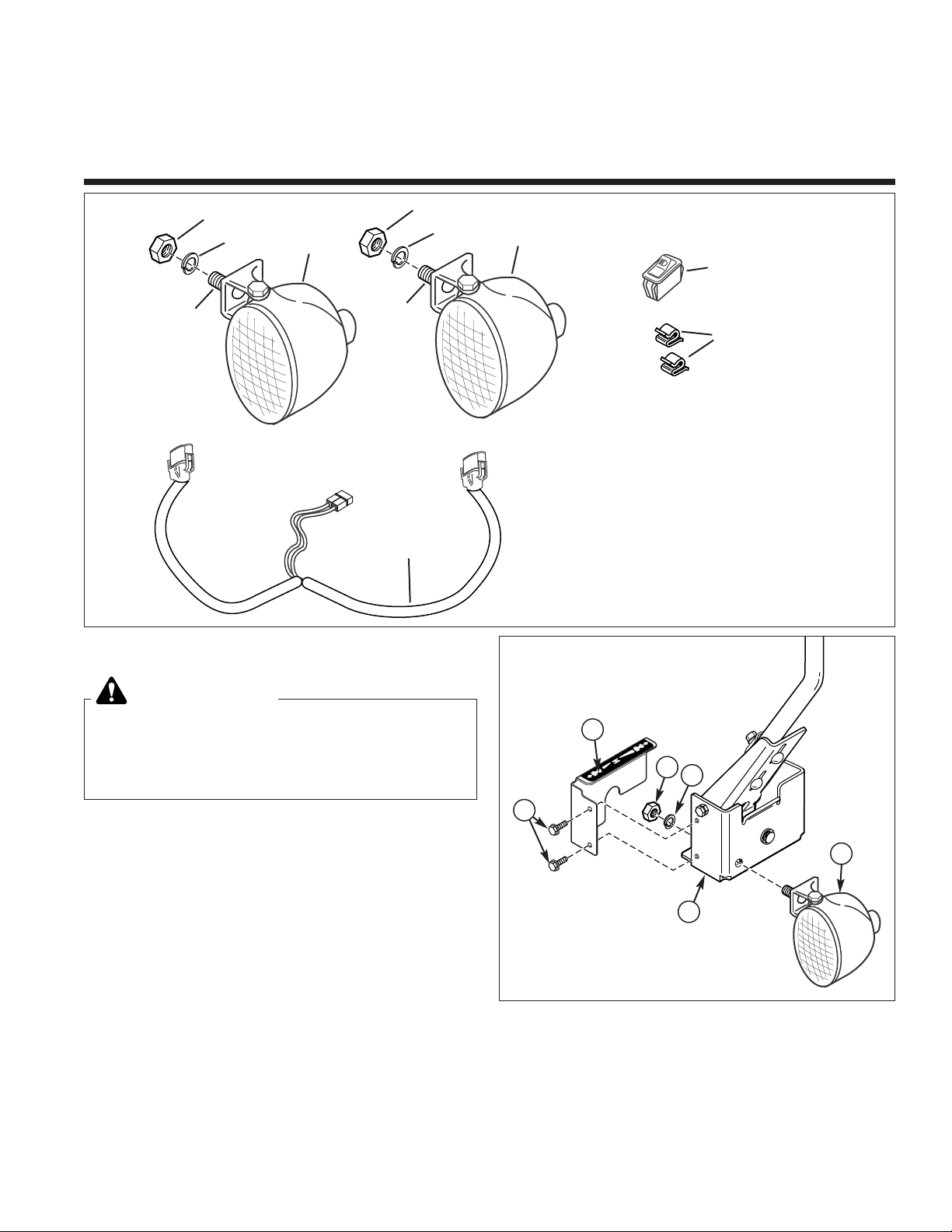
Figure 1. Contents
Kit Contents:
Ref. Part No. Qty. Description
1 N/A 2 NUT, Hex, 5/16-18
2 N/A 2 LOCKWASHER, 5/16
3 N/A 2 CARRIAGE BOLT, 5/16-18 x 1
4 1726801 2 HEADLIGHT ASSEMBLY,
(Includes Ref. Nos. 1, 2, & 3)
5 1716951 1 SWITCH, Headlight
6 2172434 2 CLIP, Wire
7 1726796 1 HARNESS, Wire
INSTALLATION
1. Remove 1/4-20 x 5/8 capscrews (A, Figure 2) and
cover (B).
2. Install light assembly (F) and secure with 5/16 lockwasher (D) and 5/16-18 nut (C).
3. Reinstall cover (B) and secure with 1/4-20 capscrews
(A).
4. Repeat steps 1 through 3 for other side of unit.
Before beginning any service work turn off the
PTO, set the parking brake, turn off the ignition,
remove the key, and disconnect the spark plug
wire(s).
WARNING
2
4
5
7
1
Figure 2. Light Installation
A. Capscrews, 1/4-20 x 5/8
B. Cover
C. Nut, 5/16-18
D. Lockwasher, 5/16
E. Bracket
F. Light Assembly
6
2
4
1
3
3
C
E
B
A
D
F
Page 2
2
Installation Instructions Light Kit
A
B
D
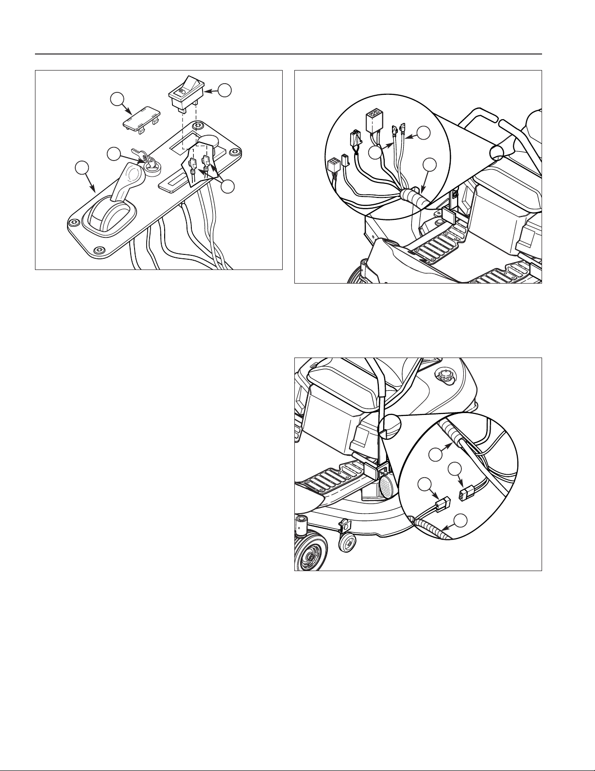
Figure 3. Switch Installation
A. Control Panel
B. Key(s)
C. Cover Plug
D. Switch, Headlight
E. Wires, Red w/Blue and Green w/Black
5. Remove key(s) (B, Figure 3) from control panel (A).
6. Lift seat to gain access to engine compartment.
7. Remove and discard cover plug (C, Figure 3) from
control panel (A).
8. Install switch (D, Figure 3) into hole in control panel
(A) with the icon in the direction as shown. Make
sure the switch is properly seated.
9. Locate a red w/blue wire (A, Figure 4) and green
w/black wire (B) taped to the main wire harness (C).
Remove tape securing the wires to harness.
10.Plug wires (E, Figure 3) into the terminals on switch
(D). Either Wire may be connected to either terminal.
11.Locate accessory connector (B, Figure 5) in the main
wire harness (A) located on the left side of engine
compartment.
12.Connect the light harness connector (C, Figure 5) to
the accessory connector (B). Make sure the connectors are joined completely.
C
E
Figure 4. Switch Wire Connections
A. Wire, Red w/Blue
B. Wire, Green w/Black
C. Wire Harness, Main
A
B
C
Figure 5. Main Power Wire Connections
A. Main Wire Harness
B. Connector, Accessory, Main Harness
C. Connector, Light Harness
D. Wire harness, Light Kit
D
B
A
C
Page 3

3
Light Kit Installation Instructions
A
E
B
Figure 6. Light Connection
A. Light
B. Harness Plug
C. Headlight Wire Harness, w/Ribbed Plastic Cover
D. Wire Clip
E. Bracket
Note: The side of the headlight wire harness with the
ribbed plastic cover (C, Figure 6) connects to the left side
light. The side of the headlight wire harness with the
braided cover goes to the right side light.
13.Connect harness plug (B, Figure 6) to the back of the
headlight (A). Make sure the connector is fully seated into the light.
14.Slide wire clip (D) onto the back side of bracket (E)
as shown. Push down to secure.
15.Slide headlight wire harness (C) into wire clip (D).
Pull slack out of headlight wire harness (C) toward
engine compartment. Route wires so they do not
contact hot or moving components.
16.Repeat step 13, 14 & 15 on the other side of unit.
17.Lower seat to normal operating position.
18.Operate control levers to be sure wires, clips and
lights do not make contact with levers. If so, readjust
components so there is no interference.
19.Reconnect spark plug.
OPERATION
1. Start the unit using normal procedures. After the unit
has warmed up and is operating at full throttle the
lights may be turned on.
2. Turn the lights off before turning off the unit. If lights
are left on with out running the unit they will drain the
battery.
Note: The headlights may dim if the RPM’s of the engine
become to low.
D
C
Page 4

4
Installation Instructions Light Kit
MANUFACTURING, INC.
500 N Spring Street / PO Box 997
Port Washington, WI 53074-0997 USA
NOTES
Form No. 1734309
Revision:00
TP 200-4583-00-AT-SN
Briggs & Stratton Yard Power Products Group
Copyright © 2007 Briggs & Stratton Corporation
Milwaukee, WI USA. All Rights Reserved
 Loading...