

Page 1
1
Installation
Instructions
Sub-Frame Hitch
Mfg. No. 1695195
For Prestige / 1800 / 2800 & Conquest / 1700 / 2700 Series
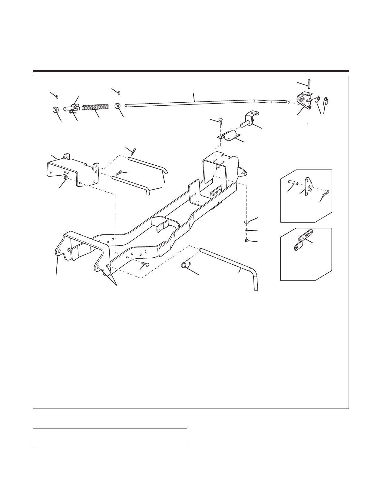
Figure 1. Contents
Kit Contents:
Ref Part No. Qty. Description
1 1733779A 1 PUSH BAR ASSEMBLY
2 1733812 2 ROD - HITCH
3 2176012 5 SAFETY CLIP
4 1723292A 1 HOOK ASSEMBLY
5 1653768A 1 CLAMP
6 2171011 1 SPRING, Compression
7 1931335 4 CARRIAGE BOLT, .31 X 1
8 1919381 4 WASHER
9 1917356 4 LOCKWASHER, .31
10 1917372 4 NUT - FULL .31-18
11 1724025A 1 LEVER ASSY - LIFT
12 2105249 1 PIN, CLEVIS
Ref Part No. Qty. Description
13 1722469 1 LOCKDOWN, HYD.
14 1722819 1 PIN, CLEVIS
15 1960033 1 CLIP, HAIRPIN
16 1722946 1 ROD, LIFT
17 8031007 2 SET, COLLAR
18 1928721 2 SCREW, .31-18 X .50
19 1723115 1 GUIDE ASSY., ROD
20 1723309 1 ROD, HITCH
21 1723795A 1 BAR, LIFT
22 1960074 2 CLIP
23 1921210 4 SCREW, .38-16 X 1
24 1928352 4 NUT, FLG, .38-16
25 1733814A 1 PUSH BAR LATCH
16
7
12
1
21
20
14
13
15
23
3
8
This kit is required when installing front-mounted
attachments.
2
9
10
5
4
3
11
17
17
6
3
19
18
18
22
22
25
24
Hydraulic
Lift
Front Hole for Dozer Applications
Rear Hole for Snowthrower Applications
Manual Lift
(
Add to early models
already present on
current models)
Page 2
2
Installation Instructions Sub-Frame Hitch
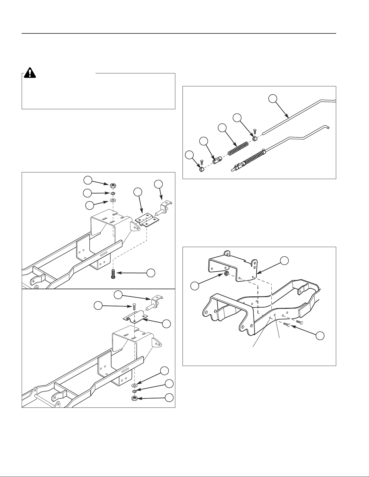
Figure 3. Assemble Lift Rod
A. Lift Rod C. Spring
B. Set Collar D. Rod Guide
B
C
D
B
A
NOTE: Please read through these instructions and the
instructions of any other attachments before beginning
installation.
INITIAL ASSEMBLY
Assemble Hitch
1. Attach the support clamp (C, Figure 2) and hook
assembly (B) to the hitch. Secure with four 5/16-18 x
1 carriage bolts (A), washers (D), lockwashers (E),
and nuts (F). Do not tighten the hardware at this
time.
WARNING
Before beginning any service work turn off the
PTO, set the parking brake, turn off the ignition,
and disconnect the spark plug wire(s).
Figure 2. Install Support Clamp
A. 5/16-18 x 1 Carriage Bolt D. 11/32 Washer
B. Hook Assembly E. 5/16 Lockwasher
C. Support Clamp F. 5/16-18 Nut
B
C
D
E
A
F
B
C
D
E
A
F
Broadmoor /
1600 / 2600
Series
Conquest / 1700 /
2700 &
Prestige / 1800 /
2800 Series
Assemble Lift Rod
1. Install the set collars (B, Figure 3), spring (C), and
rod guide (D) on the lift rod (A) as shown. Final
adjustment of the set collars will be made after the
hitch and attachment are installed.
Assemble Push Bar Latch
1. Attach Push Bar Latch (B, Figure 4), to hitch. Secure
with four .31-16 x 1 bolts (A), and four .38-16 flange
nuts (C).
B
A
C
Four Wheel
Drive Models
T wo Wheel
Drive Models
Figure 4. Assemble Push Bar Latch
A. Bolt, .38-16 x 1 C. Flange Nut, .38-16
B. Push Bar Latch
Page 3
3
Sub-Frame Hitch Installation Instructions
A
F
C
D
G
Figure 6. Lift Link - Manual Lift Models
A. Pin
B. Rear Hole of Lift Bar (Snowthrower/Dozer
Applications)
C. Spacer
D. Hair Pin Clip
E. Upper Hole (Snowthrower/Dozer Applications)
F. Slot of Lift Link (Mower Applications)
G. Lower Hole (Mower Applications)
A
B
C
D
E
Snowthrower
& Dozer
Applications
Mower
Applications
Figure 5. Lift Lock Plate - Hydraulic Lift Models
A. Lift Cylinder
B. Flat Head Pin (Original)
C. Flat Head Pin (New)
D. Lock Plate
E. Hair Pin Clips
F. Lift Shaft Assy.
G. Washers
A
B
C
D
F
E
A
B
F
G
E
Install Downward Pressure Lock
HYDRAULIC LIFT MODELS
1. Install the downward pressure lock plate (D, Figure 5)
and an additional pin (C). Note that the washers (G)
are not used with the lock plate.
MANUAL LIFT MODELS
NOTE: These instructions apply to Conquest / 1700 /
2700 Series tractors or Broadmoor / 1600 / 2600 Series
tractors equipped with a lift lever kit.
1. Install the lift link as shown in the upper frame of
Figure 6.
NOTE: The lift link on early model units had a hole located in front of the slot, rather than behind. These early
model lift links must be removed and replaced with the
one contained in this kit (Ref. No. 22, Figure 1). The lift
link included with this kit (pictured above) is universal
and works in all applications.
Snowthrower
& Dozer
Applications
Mower
Applications
Page 4

4
Installation Instructions Sub-Frame Hitch
Figure 7. Install Hitch
A. J-Hooks D. Hook
B. Hitch Rod E. Clamp Plate
C. Hitch Rod
A
B
D
E
Install Hitch
1. Slide the hitch under the tractor.
2. Raise the rear of the hitch and place the hook (C)
over the lift shaft.
3. Connect the front of the hitch to the tractor J-hooks
(A, Figure 7) using the hitch rod (B) and a safety clip
in the top holes of the push bar latch.
4. Secure the front of the hitch to the tractor by attaching the hitch rod (C) and a safety clip in the bottom
holes of the push bar latch.
C
5. Push the clamp plate (D) backwards until it is snug
against the lift shaft. Tighten the clamp plate hardware (E).
Page 5
5
Sub-Frame Hitch Installation Instructions
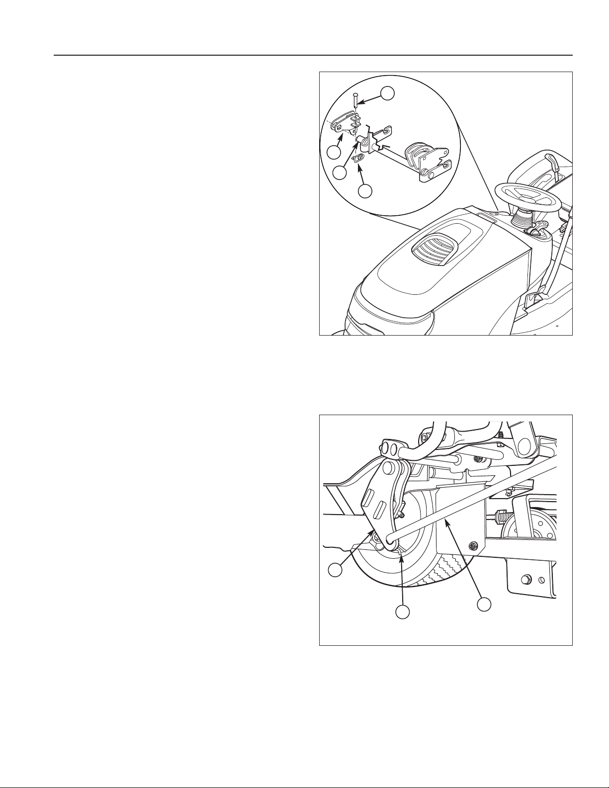
Install Lift Rod
1. Slide the lift lever (A, Figure 8) onto the end of the
tractor lift shaft (B) under the right side footrest.
2. Use the tabs on the lift lever (A) to capture the tractor
lift arm. Secure in place with a clevis pin (D) and
safety clip (C).
Figure 8. Install Lift Lever
A. Lift Lever
B. Lift Shaft
C. Safety Clip
D. Clevis Pin
Figure 9. Install Lift Rod
A. Lift Lever
B. Lift Rod
C. Clip
A
C
B
D
3. Insert the rear of the lift rod (B, Figure 9) into the bottom of the lift lever (A). Secure with a clip (C).
Perform lift rod adjustment according to the procedure
found in the attachment operator’s manual.
A
C
B
Page 6

6
Installation Instructions Sub-Frame Hitch
REMOVAL
NOTE: After removing components, reinstall the clevis
pins and clips to prevent loss.
1. Disconnect the lift rod from the attachment and lift
lever (C, Figure 10).
2. Remove the clevis pin and clip from the lift lever (C)
and remove the lift lever.
3. Remove the front hitch rods (A) and (B). Remove the
hitch and hook (F).
4. Remove the lock plate (D, E) or switch the lift link
from dozer to mowing position (see page 7).
NORMAL INSTALLATION
1. Insert the hook (F, Figure 10) into the back of the
hitch. Mount the rear of the hitch on the lift crossshaft.
2. Secure the front of the hitch to the J-hooks using the
hitch rods (A) and (B) (Figure 7).
3. Install the downward pressure lock plate or switch the
lift link (see page 7).
4. Install the lift lever (C).
5. Install the lift rod and attachment (Figure 8).
Figure 10. Normal Installation & Removal
A
C
D
E
F
A. Hitch Rod
B. Hitch Rod
C. Lift Lever
D. Pressure Lock Plate
(Manual)
E. Pressure Lock Plate
(Hydraulic)
F. Hook
OBSOLETE
B
Page 7

7
Sub-Frame Hitch Installation Instructions
A
F
C
D
G
Figure 12. Lift Link - Manual Lift Models
A. Pin
B. Rear Hole of Lift Bar (Snowthrower/Dozer
Applications)
C. Spacer
D. Hair Pin Clip
E. Upper Hole (Snowthrower/Dozer Applications)
F. Slot of Lift Link (Mower Applications)
G. Lower Hole (Mower Applications)
A
B
C
D
E
Snowthrower
& Dozer
Applications
Mower
Applications
Figure 11. Lift Lock Plate - Hydraulic Lift Models
A. Lift Cylinder
B. Flat Head Pin (Original)
C. Flat Head Pin (New)
D. Lock Plate
E. Hair Pin Clips
F. Lift Shaft Assy.
G. Washers
A
B
C
D
F
E
A
B
F
G
E
LIFT V ARIA TIONS WHEN USING
ATTACHMENTS
When a front-mounted attachment such as a snowthrow-
er or dozer blade is used with the tractor, the lift mechanism must be locked to provide downward force. When
the mower is reinstalled the downward pressure lock
must be released so that the mower can float.
Hydraulic Lift Models
When using a snowthrower or dozer, the downward
pressure lock plate (D, Figure 11) and an additional pin
(C) is installed. These parts are included with the attachment. Note that the washers (G) are not used with the
lock plate.
When mowing, the downward pressure lock plate (D) is
removed and replaced with two washers (G). The additional pin (C) is also removed.
Fully lower the hydraulic lift. The lift assembly is spring
loaded so it will need to be held in the down position to
perform of the following procedures.
Manual Lift Models
NOTE: These instructions apply to Conquest / 1700 /
2700 Series tractors or Broadmoor / 1600 / 2600 Series
tractors equipped with a lift lever kit.
The lift link is installed differently depending on what
attachment is being used. Refer to Figure 12 for link
installation information.
Snowthrower
& Dozer
Applications
Mower
Applications
Page 8

8
Installation Instructions Sub-Frame Hitch
Form No. 1733910-03
Rev. 12/2006
© 2006 Briggs & Stratton, Inc. All Rights Reserved
TP 200-4442-03-AT-SMAN
MANUFACTURING, INC.
500 N Spring Street / PO Box 997
Port Washington, WI 53074-0997 USA
Figure 4. Install Lock Plate - Manual Lift Models
A. Lift Shaft Assy. F. Lift Bar
B. Flat Head Pin (Original) G. Lock Plate
C. Flat Head Pin (New) H. Hair Pin Clips
D. Capscrew I. Spacer
E. Washer
A
B
C
D
E
F
F
G
G
H
I
DOWNWARD PRESSURE LOCK
PLATE - OBSOLETE
Note:The following information applies only
to models produced before October of 2002.
It is being included here for reference purposes ONLY.
MANUAL LIFT MODELS
1. Rest the back of the lock plate (G, Figure 4) against
the spacer (I) and rotate until it lines up with the hole
in the lift bar (F).
2. Secure the lock plate (G) to the lift bar (F) using a flat
head pin (C) and hair pin clip (H).
 Loading...