

Page 1
OWNER'S MANUAL
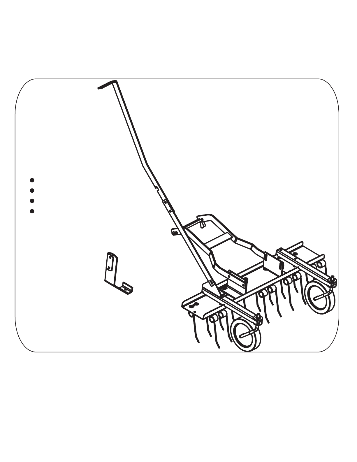
THATCHER
MODEL:
1695066
Assembly
Installation
Operation
Repair Parts
Important: This manual contains information for the safety of
persons and property. Read it carefully before assembly and
operation of the equipment!
L-1782-BH-01
Page 2
2.
L-1782-BH-01
Page 3

HARDWARE REFERENCE
Tools Required for Assembly:
* 7/16" wrench
* 1/2" wrench
* Flat Head Screwdriver
* Hammer
* Pair pliers
L-1782-BH-01
3.
Page 4

Parts Reference
Parts List
REF.
NO.
1
2
3
4
5
6
7
8
9
10
11
12
13
14
15
16
17
19
20
22
23
25
26
27
28
29
30
31
32
33
PART NO.
B-983
B-1673P
C-123
R-618
R-635-01
R-636
R-637-01
R-640
R-653
R-704
R-705-10
R-713-10
R-746
R-755-10
R-1503
R-1835-10
R-2466-10
R-2474-10
R-2473-10
R-775-10
R-803
10M0840P
11M1016P
30M1000P
40M1000P
45M1111P
45M1717P
R-2469-01
R-2475-01
R-2476-10
QTY.
1
4
2
10
2
2
2
2
10
4
2
2
1
1
2
1
1
1
1
1
1
4
21
23
21
3
4
1
1
1
DESCRIPTION
Hair pin cotter
Hex Lock Nut, 1/4"
Gauge wheel
Reinforcing washer (special)
Locking collar
Push nut
Axle
Set screw (slotted), 5/16"
Thatching Tine
Nylon bearing, 1/2"
Wheel support
Bracket (tray mounting)
Lift pin
Tray
Tine Safety wire
Bracket (lift)
Mounting frame
Lift handle rear
Lift lock bracket
Handle retaining strap
Handle grip
Carriage bolt, 1/4" x 2-1/2"
Carriage bolt, 5/16" x 1"
Hex nut, 5/16"
Lock Washer, 5/16"
Plain Washer, 5/16"
Plain Washer, 1/2"
Rod, Small
Rod, Large
Handle Extention
4.
L-1782-BH-01
Page 5

EXPLODED REFERENCE
19
23
32
31
17
28
27
27
27
22
28
27
27
26
15
26
20
4
9
20
28
1
16
29
33
25
29
2
28
26
13
27
27
28
4
10
26
12
26
5
11
8
27
25
28
7
2
26
10
14
11
5
8
6
30
28
27
7
30
30
6
6
30
3
5.
L-1782-BH-01
Page 6

Step 1.
25
2
25
1/4" x 2-1/2", Carriage Bolt
Qty. 4
25
2
2
Hex Lock Nut
Qty. 4
Step 2.
26
5/16" x 1", Carriage Bolt
Qty. 2
L-1782-BH-01
6.
26
4
27
28
26
4
28
4
Reinforcing Washer
Qty. 2
27
27
Hex Nut
Qty. 4
28
5/16" Lock Washer
Qty. 4
Page 7

Step 3.
26
4
26
5/16" x 1", Carriage Bolt
Qty. 8
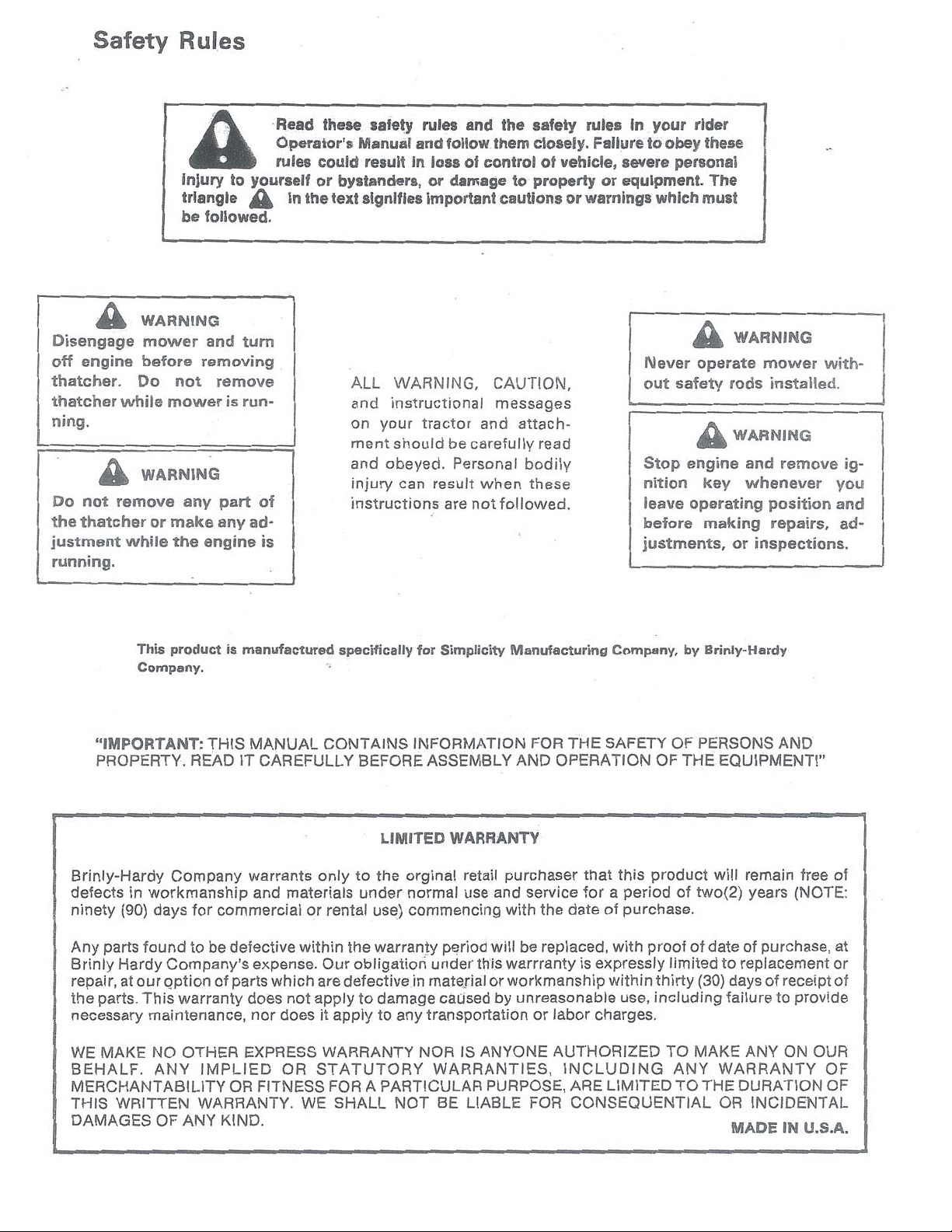
WARNING: Failure to install safety wires can result in personal injury
!
if a tine should disengage from tine tray.
Step 4.
27
Hex Nut
Qty. 8
4
Reinforcing Washer
Qty. 8
15
28
27
28
5/16" Lock Washer
Qty. 8
L-1782-BH-01
7.
Page 8

Step 5.
27
28
27
Hex Nut
Qty. 4
26
5/16" x 1", Carriage Bolt
Qty. 2
Step 6.
28
5/16" Lock Washer
Qty. 2
26
28
27
8.
7
30
6
Push Nut
Qty. 2
3
6
30
1/2" Flat Washer
Qty. 4
L-1782-BH-01
Page 9

Step 7.
10
5
5
Locking collar
Qty. 2
10
1/2", Nylon Bearing
Qty. 4
Step 8.
8
5/16", Set Screw
Qty. 2
27
28
22
27
20
26
8
10
27
Hex Nut
Qty. 4
5/16" x 1", Carriage Bolt
5/16" Lock Washer
Qty. 2
26
Qty. 2
28
Step 9.
3"
A 11/32" diameter hole needs to be drilled
in right side of your tractor frame above
front tire. Layout and drill the hole 3"
from front of and center of frame lip.
L-1782-BH-01
9.
Page 10

Step 10.
Assembly Lift Lock bracket assembly
to tractor under frame where the hole
was drilled in previous step.
26
26
5/16" x 1", Carriage Bolt
Qty. 1
Step 11.
27
28
26
5/16" x 1", Carriage Bolt
Qty. 2
5/16" Flat Washer
29
Qty. 3
27
Hex Nut
Qty. 1
27
Hex Nut
Qty. 2
28
5/16" Lock Washer
Qty. 1
28
5/16" Lock Washer
Qty. 2
1
Hairpin Cotter
Qty. 1
26
27
28
13
Lift Pin
Qty. 1
13
29
1
10.
L-1782-BH-01
Page 11

Step 12.
Adjustment
For most lawns, adjust the thatcher as follows:
1. Select a smooth flat surface such as a driveway,
sidewalk, garage floor, etc. Attach the thatcher to
the tractor according to the mounting instructions.
Be sure both gauge wheels are directly under the
wheel support.
2. Loosen the four nuts on the sides of the "L"
shaped tray mounting brackets, and the gauge wheel
set screws. Adjust the tine tray to place the tine tips
approximately 1/2" above the flat surface when in
free position and to touch the flat surface when pushed
back.
3. Tighten all nuts and gauge wheels set screws.
32
Remove existing mower deck
mounting pin from front of tractor.
Assemble the Large or Small rod
depending on whether tractor is
a Simplicity or Snapper. Secure
using retaining ring previously
removed.
31
!
OPERATION
Tine ACTION- Grass should be less than 3" tall for proper
tine action.
When in use, all tines on the De-thatcher should deflect
back and "flip" the thatch forward as shown in illustraion.
If the tines seem to drag without flipping forward, the tine
tray is too low and should be raised.
If all the tines stay in the free position, the tray should be
lowered.
Make adjustments as necessary, up or down, by no more
than 1/4" each time, until proper results are achieved.
!
MAINTENANCE
The key to years of trouble-free service is to keep your
Sweeper clean and dry.
Occasionally check all moving parts for free movement and,
if necessary, lubricate with oil.
Should rust develop, sand lightly and then paint area with
enamel.
Periodically check all fasteners for tightness.
L-1782-BH-01
11.
 Loading...