

Page 1
1
Installation
Instructions
Lift Lever Kit
Mfg. No. 1694947
For Broadmoor / 200 / 1600 / 2600 Series
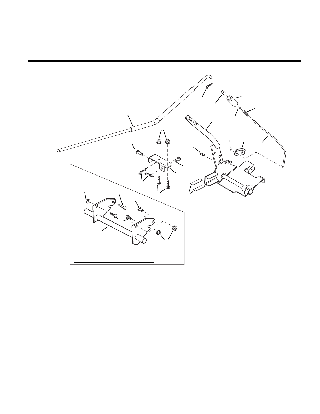
Figure 1. Contents
Kit Contents:
Ref Part No. Qty. Description
1 1725959A 1 ROD & TUBE ASSEMBLY
2 1960033 1 CLIP, Hair Pin
3 1723124 1 BUTTON, Red
4 1713995 1 GRIP, Soft, Black
5 1960674 1 PUSH NUT, 1/4
6 1723321 1 SPRING, Compression
7 1725958 1 ROD, Latch
8 1721999A 1 LATCH, Lift Lever
9 1960126 1 PUSH NUT, 1/4
10 1727441A 1 LEVER ASSEMBLY
11 1927609 1 PIN, 3/8 x 1
12 1931277 6 NUT, Hex, Flange Whiz Lock, 5/16-18
13 1708298 2 PIN, Round Head, Drilled, 3/8 x 1
14 1725705A 1 BRACKET, Mounting
15 1960074 2 CLIP, Hair Pin
16 1960585 2 CAPSCREW, Hex Head,
5/16-18 x 1-3/4
17 1725957 2 PAD, Rubber
18 2826149 3 CAPSCREW, Hex Head,
5/16-18 x 1
19 1960636 3 NUT, Hex, KEPS, 5/16-18
20 1731381A 1 SHAFT ASSEMBLY
21 1921221 1 CAPSCREW, Hex Head,
5/16-18 x 1-1/2
1
2
3
4
5
6
7
8
9
10
11
13
13
12
16
15
14
21
20
17
19
19
18
18
Used on single point pick-up
mowers only. See Figures 2 & 3
Page 2

2
Installation Instructions Lift Lever Kit
INSTALLATION
ALL MODELS
1. Remove mower deck as described in the Operator’s
Manual.
2. Remove nuts (A, Figure 4) and capscrews (B) which
hold the right rear seat deck (C) to the frame(D).
Discard capscrews.
3. Install bracket (E, Figure 5) using new 5/16-18 x 13/4 capscrews (B) and 5/16-18 nuts (A).
This kit adds a lift lever for front mounted
attachments.
Before beginning any service work turn off the
PTO, set the parking brake, turn off the ignition,
and disconnect the spark plug wire(s).
WARNING
Figure 4. Capscrew Removal
A. Nuts C. Right Rear Seat Deck
B. Capscrews D. Frame
Figure 5. Bracket installation
A. Nuts D. Frame
B. Capscrews E. Bracket
C. RIght Rear Seat Deck
A
D
B
C
A
D
B
C
E
Figure 3. Typical Single Point Pick-Up
A. Bell Crank Assembly C. Lift Lever
B. Lift Rod
A
B
Note: Dual point pick-up mowers have the lift attached at
two points on the mower deck. See Figure 2. Lift shaft
assembly (A) is already installed on these tractors.
Do not replace with lift shaft assembly provided in kit.
Single point pick-up mowers have the lift attached at one
point on the mower deck. See Figure 3.
Mower Lift
Point
C
Figure 2. Typical Dual Point Pick-Up
A. Lift Shaft Assembly C. Lift Lever
B. Lift Rod
A
B
Mower Lift
Points
C
Page 3

3
Lift Lever Kit Installation Instructions
3. Mount the lift shaft assembly (A, Figure 7) to the
frame using three 5/16-18 x 1 capscrews (B) and
5/16-18 flange nuts (C) as shown.
4. Install 5/16-18 x 1-1/2 capscrew (D), spacer (F), bell
crank (G), washer & 5/16-18 nut (I).
5. Install rod (H), and hair pin & washer (E) if removed.
Figure 7. Install Lift Shaft Assembly & Rod.
A. Lift Shaft Assembly E. Hair Pin & Washer
B. Capscrews, Hex F. Spacer
5/16-18 x 1 G. Bell Crank
C. Flange Nuts, 5/16-18 H. Rod
D. Capscrew, Hex I. Washer & Nut, 5/16-18
5/16-18 x 1-1/2
B
C
A
Figure 6. Rod & Bell Crank Removal
A. Hair Pin E. Spacer
B. Washer F. Bell Crank Assembly
C. Rod G. Washer
D. Capscrew H. Nut
A
A
B
C
D
E
F
H
G
B
G
F
H
Install Lift Shaft Assembly
SINGLE POINT PICK-UP MODELS ONLY
1. Remove and retain spacer (E, Figure 6), bell crank
assembly (F), washer (G), and nut (H). You may find
installation easier to remove rod (C) and one cotter
pin (A) and washer (B).
2. Remove and discard capscrew (D).
B
C
D
I
E
E
Page 4

4
Installation Instructions Lift Lever Kit
Figure 8. Install Lift lever Assembly.
A. Lift Lever Assembly C. Hair Pin
B. Clevis Pin D. Mounting Bracket
C
Install Front Attachment Lift Lever & Rod
ALL MODELS
1. Slide the lift lever assembly (A, Figure 8) on to the
end of the shaft assembly and on to the edge of the
tractor.
2. Secure to mounting bracket (D) using clevis pins (B)
and hair pin (C).
B
B
A
Edge of
Tractor
End of
Shaft
Assembly
D
B
Figure 9. Install Lift Rod
A. Lift Rod C. Hair Pin
B. Lift Lever Assembly
A
C
3. Slide lift rod (A, Figure 9) into the bottom hole in the
lift lever assembly (B). Secure with hair pin. Install
front attachment & hitch as outlined in Operator’s
Manual or Installation Instructions.
4. Removal of Front Attachment Lift Lever & Rod is
reverse of installation.
Note: Substitute lift rod A, Figure 9 for the lift rod provided in the attachment hitch.
Form No. 1731401
Revision 01 Rev. Date 11/2005
© 2005 Simplicity Manufacturing, Inc. All Rights Reserved
TP 200-4229-01-AT-SMAN
MANUFACTURING, INC.
500 N Spring Street / PO Box 997
Port Washington, WI 53074-0997 USA
 Loading...