

Page 1
1
Installation
Instructions
54”Turbo Blower
Mfg. No. 1693706, 1695299
For 54” Mower Decks
SAFETY RULES
Read these safety rules, and the safety rules in
your tractor Operator’s Manual, and follow them
closely. Failure to obey these rules could result
in loss of control of vehicle, severe personal
injury to yourself, or damage to property or
equipment. THE TRIANGLE IN THE TEXT
SIGNIFIES IMPORTANT CAUTIONS OR WARNINGS WHICH MUST BE FOLLOWED.
WARNING
● When blower assembly is removed from the mower
deck, the deflector must be properly installed.
● If the mower stalls or the turbo blower chute plugs,
disengage the electric clutch (PTO), stop the engine
and remove the key. set the parking brake. wait for
moving parts to stop. Remove the foreign object or
clear the chute with a piece of wood before restarting
the engine. Never place hands into blower housing to
clear jammed object. Blower may rotate when object
is removed.
● For added tractor stability and to prevent tipping or
loss of control:
a. Use reduced speed on uneven ground and when
turning corners.
b. Reduce loads on hillsides. It is recommended that
the collection system be kept only half full when
negotiating any slopes. Start mowing on slopes
when the collection system is empty.
c. Mow up and down the face of slopes; never
across the face of any slope.
● When operating on slopes, use front counterweight.
Never operate on slopes greater than 17.6% (10°).
● Know the tractor controls and how to stop quickly.
READ THE TRACTOR OPERATOR’S MANUAL.
● Disengage the electric clutch (PTO). Shut off the
engine, remove the key, and wait for all moving parts
to stop before attaching, adjusting, or disconnecting
any part of the collection system.
● Check the collection system to make sure it is bolted
tightly to the tractor.
● Look behind to make sure the area is clear before
backing up.
● DO NOT turn sharply when travelling alongside a
building or any object.
● DO NOT carry passengers on the tractor.
● Read and obey all warning decals.
OPERATION
Operation With Turbo
• Grass should be cut often but not too short. If grass is
too long or lush, it may be necessary to keep ground
speed to a minimum or to cut only half the width to
prevent clogging. If grass is too high, operate with
mower in high cutting position. Cut the grass again in
lower cutting position, if desired.
• Before mowing, clear the lawn of all sticks, stones,
wire and other debris which may be caught or thrown
by the mower blades.
• The blower housing should be removed for cleaning.
If a large amount of cut grass is spilling out from
under the deck, the tube may be plugged or grass
bags are full. Shut off tractor, disengage the PTO,
remove the key, and allow all moving parts to stop
before disconnecting the tube.
• Always operate at full throttle speed.
Operation Without Turbo
• For operation without the turbo, the deflector must be
properly installed in the down position and retained
by the spring latch.
• To remove turbo, reverse the installation steps.
Recommended Accessories
• Front counterweight is recommended when using
rear-mounted grass catcher.
• On slopes over 17.6% (10°), use two rear wheel
weights in addition to front counterweight.
Always mow up and down the face of slopes, never across
the face. Never mow on slopes greater than 30% (16.7
degrees)
NOTE: In these instructions, “left” and “right” are
referred to as seen from the operating position.
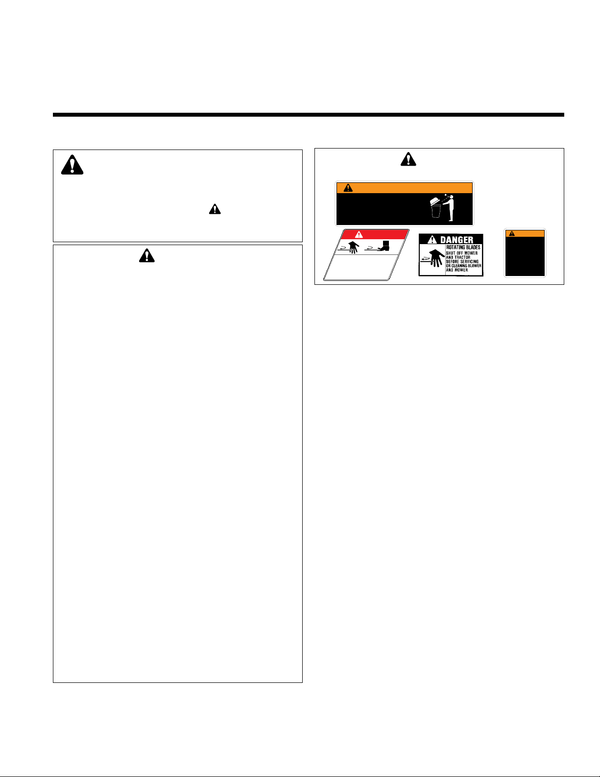
WARNING
Read and obey all operation and warning decals.
WARNING
• Do not open cover with engine running.
• Do not operate mower without the
complete catcher in place
• When operating on slopes, refer to
operator's manual for counterweights.
DANGER
ROTATING CUTTING BLADE
Do not operate mower
without deflector or entire
grass catcher in place.
1704277
1704405
WARNING
• This shield must be
in place at all times
during operation.
• Mower deflector
must be in down
position when
blower is removed.
1717291
Page 2
2
Installation Instructions 54”Turbo Blower
38
1
2
41
3
6
40
5
4
7
8
9
25
52
55
51
50
46
53
48
49
47
45
54
44
58
57
56
60
31
19
20
37
24
64
65
66
67
68
23
43
42
21
33
34
32
26
28
35
36
29
27
17
12
15
22
11
14
13
18
16
10
30
59
5
1
1
2
1
17
19
20
27
5
3
19
20
20
19
31
37
46
46
39
27
46
61
62
63
Page 3

3
54”Turbo Blower Installation Instructions
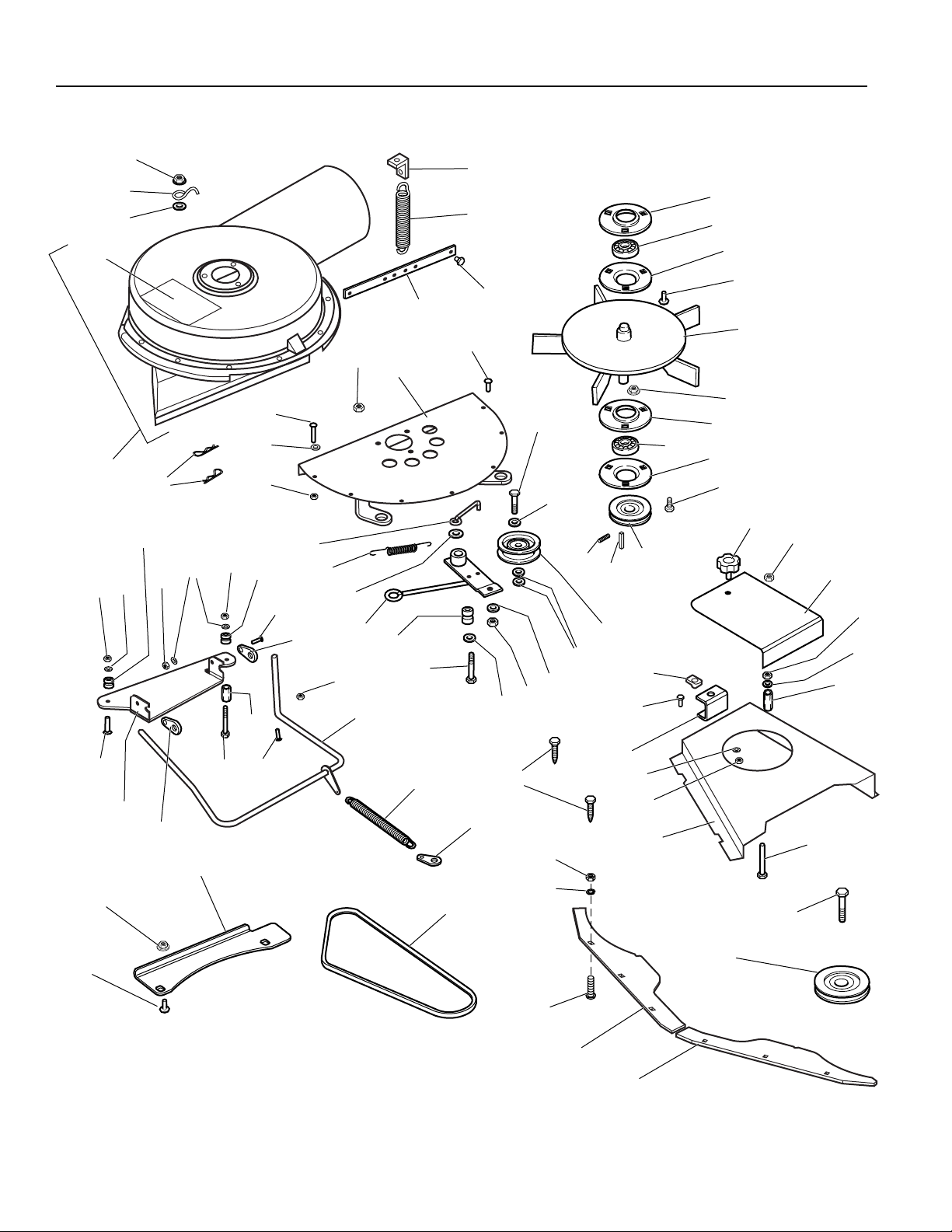
Kit Contents:
Ref Part No. Qty. Description
1 1665982 4 RETAINER, Bearing
2 108202 2 BALL BEARING
3 1931333 5 CARRIAGE BOLT, 5/16-18 x 3/4
4 1706631 1 FAN ASSY
5 1927557 8 FLANGE LOCKNUT, 5/16-18
6 1921332 3 CAPSCREW, .312-18X0.750 G5
7 1706634 1 PULLEY
8 960403 1 KEY, Woodruff
9 1960619 1 SET SCREW, Torx, 5/16-18 x 5/16
10 1935255 1 SPEED NUT
11 1919438 1 NYLOCK NUT, 5/16-18
12 1720918 1 COVER
13 1917372 1 NUT, 5/16-18
14 1917356 1 LOCKWASHER, 5/16
15 1713588 1 SPACER
16 1935255 1 PAL NUT, 5/16-18
17 1921959 4 CAPSCREW, 1/4-20 x 5/8
18 1700654 1 BRACKET, Belt Cover
19 1916964 4 LOCKWASHER, 1/4
20 1916622 4 NUT, 1/4-20
21 1721454A 1 COVER, Arbor
22 1921719 1 CAPSCREW, 5/16-18 x 2-1/2
23 1927120 1 CAPSCREW, 7/16-14 x 2-1/4
24 1720737 1 PULLEY & HUB ASMY
25 1720932 1 V-BELT
26 1720749 1 SUPPORT PLATE
27 1720921 3 LOCKING TAB
28 1719590 1 SPRING, Extension
29 1720920 1 PLATE, Deflector Mounting
30 1931320 1 CARRIAGE BOLT, 1/4-20 x 1-1/4
31 1720718 2 PILOT PIN, Tapered Spacer
32 1933896 4 LOCKNUT, 10-24
33 1720951 1 ROD & ANCHOR ASMY, Deflector
34 1960404 4 SCREW, Truss Head, 10-24 x 3/4
Kit Contents:
Ref Part No. Qty. Description
35 1921159 1 CAPSCREW, 1/4-20 x 2-1/4
36 1720978 1 SPACER, 5/8 x 1
37 1704628 2 PIN, Spring
38 1720892 1 HOUSING, with Decal
39 1700259 1 DECAL-Danger
40 1933988 3 PAL NUT, 5/16
41 1672689 1 S-HOOK
42 1927429 3 TAPTITE SCREW, 1/4-20 x 5/8
43 1706630 1 STRAP
44 1960472 6 SCREW, Truss Head, 1/4-20
45 1921969 1 CAPSCREW, 3/8-16 x 1-1/2
46 1924940 4 WASHER, 3/8
47 1708029 1 PULLEY, Idler
48 1916965 2 LOCKWASHER, 3/8
49 1916950 2 NUT, 3/8-16
50 1923701 1 CAPSCREW, 3/8-16 x 2
51 1666114 1 BUSHING
52 1720934 1 LEVER ASMY
53 1922755 1 WASHER, 3/8
54 174896 1 SPRING, Extension
55 1704419 1 BELT STOP
56 1930641 8 LOCKNUT, 1/4-20
57 1921319 1 WASHER, 1/4
58 1921961 1 CAPSCREW, 1/4-20 x 1-1/4
59 1930645 1 NUT, 3/8-16
60 1720721 1 PLATE & BRACKETS ASMY
61 1929000 2 TAPTITE SCREW
62 1668500 1 BRACKET
63 1672735 1 SPRING
64 1917372 6 NUT, 5/16-18
65 1917356 6 LOCKWASHER, 5/16
66 1931333 6 CARRIAGE BOLT, 5/16-18 x 3/4
67 1721023 1 BAFFLE, RH, 26-1/2”
68 1720613 1 BAFFLE, LH, 23-1/2”
Page 4

4
Installation Instructions 54”Turbo Blower
Figure 1. Install Hook Plate
A. 5/16-18 x 3/4 Carriage Bolts
B. Hook Plate
C. Deck Shell
D. Flange Locknuts
E. Clips
B
C
E
A
D
D
INITIAL INSTALLATION
NOTE: When installing this attachment on early models,
the rivets securing the clips (E, Figure 1) must be drilled
out, and the new belt cover secured with taptite screws
supplied.
NOTE: The following procedure can be performed with
the mower installed on the tractor, however for ease of
installation, removing the mower deck is recommended
Install Hook Plate
1. Remove the right side belt cover and retain taptite
screws.
2. Remove the deflector, spring, and hinge assemble.
Retain the hardware except for the carriage bolts.
Use a hammer to drive the carriage bolts back
through the deck, and discard the bolts.
3. Install the hook plate (B, Figure 1) below the stone
guard using two 5/16-18 x 3/4 carriage bolts (A) and
flange locknuts (D). Install the bolts from the bottom
up.
WARNING
Before beginning any service work turn off the
PTO, set the parking brake, turn off the ignition,
and disconnect the spark plug wire(s).
Figure 2. Install New Arbor Pulley
A. Capscrew C. Washer
B. Lockwasher D. Pulley and Hub
Assy.
Stone
Guard
Stone
Guard
A
B
C
D
Install Pulley
1. Remove the right arbor capscrew, lockwasher, and
washer. Discard the capscrew; retain the lockwasher
and washer.
2. Install the pulley and hub assembly (D) on top of the
original pulley. Secure with a new 7/16-15 x 2-1/4
capscrew (A) and original lockwasher (B) and washer
(C). Torque to 55-75 ft. lbs.
Page 5

5
54”Turbo Blower Installation Instructions
Install Deflector
1. Locate the taptite screw (A, Figure 3) securing the
inner right-hand belt cover spring clip (C). Remove
the taptite screw (A).
2. Install the spring anchor (B) above the belt cover clip
(C) and secure using the original taptite screw (A).
3. Install the new right hand belt cover assembly (E)
using the original taptite screws removed in Step 1.
4. Assemble the hinge rod (B, Figure 4) and hinge
bracket (F). Secure using the rod anchors (A), 1/4-20
x 5/8 capscrews (E), lockwashers, and nuts as
shown.
5. Drill four 13/64” holes at the marked locations on the
underside of the deflector assembly (E, Figure 5).
6. Secure the deflector (C, Figure 5) to the deflector
hinge assembly (B) using four 10-24 x 3/4 truss head
screws (D) and nylock nuts (A). Insert the screws
from the bottom.
Figure 3. Install Cover & Spring Anchor
A. Taptite Screw D. Roller Bar Retainer
B. Spring Anchor E. New Arbor Cover Assy.
C. Cover Clip
Figure 4. Assemble Hinge
A. Rod Anchors D. 1/4-20 Nut
B. Hinge Rod E. 1/4-20 x 5/8 Capscrew
C. 1/4” Lockwasher F. Hinge Bracket
A
Figure 5. Assemble Deflector
A. 10-24 Locknut
B. Hinge Assembly
C. Deflector
D. 10-24 x 3/4 Truss Head Screw
E. 13/64 Holes
A
B
C
D
E
B
E
C
D
A
B
E
E
F
C
D
D
C
Page 6

6
Installation Instructions 54”Turbo Blower
7. Install the new deflector and hinge assembly.
Secure the front of the hinge bracket using a new
1/4-20 x 1-1/4 carriage bolt (B, Figure 6), one tapered
spacer (D), lockwasher, and nut (E).
Secure the back of the hinge bracket using a new
1/4-20 x 2-1/4 capscrew (A), 13/16 x 1 cylinder spacer (F), tapered spacer (D), and original lockwasher
and nut (E).
Figure 6. Install Deflector and Hinge Assembly
A. 1/4-20 x 2-1/4 Capscrew
B. 1/4-20 x 1-1/4 Carriage Bolt
C. Hinge & Deflector (Deflector Removed for Clarity)
D. Tapered Spacer
E. Original Lockwasher and Nut
F. 5/8 x 1 Cylinder Spacer
Figure 7. Connect Deflector Spring
A. Spring Anchor
B. Spring
C. Deflector Arm
A
B
C
D
E
E
D
F
A
B
C
8. Install the deflector spring (B, Figure 7). Attach the
centered leg to the deflector arm (C). Attach the offset leg to the spring anchor (A).
Tapered
Spacer
Page 7

7
54”Turbo Blower Installation Instructions
FRONT
Install Turbo Blower
1. Install the turbo blower assembly. Insert the tapered
spacers (B, Figure 8) through the bottom of the blower housing (A).
2. Install one spring clip (C) on both tapered spacers
(B).
3. Hook the bottom of the turbo on the bottom hook
bracket.
4. Use the release lever to release tension on the belt,
and install the belt on the new arbor pulley (see
Figure 9).
5. Rotate the belt cover into position and secure with
the plastic knob (D, Figure 8).
6. If not already done, install the bracket (E) using the
existing capscrew.
7. Install the spring (F). Connect the top of the spring to
the bracket (E) and the bottom to the hole in the
mower deck shell, just behind the discharge opening.
Install Baffles
1. Remove and discard the existing baffle from the left
side of the mower. It is replaced by turbo baffles.
2. Install the left (23-1/2” long) baffle and right (26-1/2”)
front baffle (B & C, Figure 10) using six 5/16-18 x 3/4
carriage bolts (A), lockwashers, and nuts (D). Be
sure the bolts are inserted fully into the slots in the
mower deck.
Figure 8. Install Turbo
A. Turbo Blower Assy. D. Plastic Knob
B. Tapered Spacers E. Bracket
C. Spring Clips F. Spring
A
E
F
B
C
C
B
D
Figure 9. Belt Routing
Figure 10. Install Front Baffles
A. 5/16-18 x 3/4 Carriage Bolts
B. Left Front Baffle (23-1/2” Long)
C. Right Front Baffle (26-1/2” Long)
D. 5/16-18 Nut and Lockwasher
C
B
D
D
A
A
Page 8

Installation Instructions 54”Turbo Blower
Form No. 1720927-06
Rev. 03/2007
© 2007 Briggs and Stratton, Inc. All Rights Reserved
TP 200-2325-06-AT-SMA
MANUFACTURING, INC.
500 N Spring Street / PO Box 997
Port Washington, WI 53074-0997 USA
NORMAL INSTALLATION AND
REMOVAL
Installation
1. Insert the tapered spacers (B, Figure 11) through the
bottom of the blower housing (A).
2. Install one spring clip (C) on each of tapered spacers
(B).
3. Hook the bottom of the turbo on the bottom hook
bracket.
4. Use the release lever to release tension on the belt,
and install the belt on the arbor pulley (see Figure
12).
5. Rotate the belt cover into position and secure with
the plastic knob (D, Figure 11).
6. Install the spring (F). Connect the top of the spring to
the bracket (E) and the bottom to the hole in the
mower deck shell, just behind the discharge opening.
Removal
1. Remove the spring (F, Figure 11).
2. Loosen the plastic knob (D, Figure 11).
3. Use the release lever to release tension on the belt,
and remove the belt from the arbor pulley (Figure 12).
4. Remove the spring clips (C, Figure 11) from the
tapered spacers (B).
5. Remove the turbo assembly (A) from the deck.
6. Close the small belt cover and secure with the plastic
knob (D, Figure 11).
7. Return the deflector to the down position.
NOTE: The baffles (Figure 10) do not need to be
removed.
FRONT
Figure 12. Install Turbo
WARNING
The deflector must be properly installed in the
down position and retained by the spring. Do not
operate the unit without a deflector.
Figure 11. Install Turbo
A. Turbo Blower Assy.
B. Tapered Spacers
C. Spring Clips
D. Plastic Knob
E. Bracket
F. Spring
A
E
F
B
C
C
B
D
 Loading...