

OPERATOR’S
MANUAL
42”/48”
Turbo Blower Assembly
Mfg.
No:
1691810
Mfg. No. 1691998
FORM 170460604
PRINTED IN U.S.A.
12/93-3ooccI
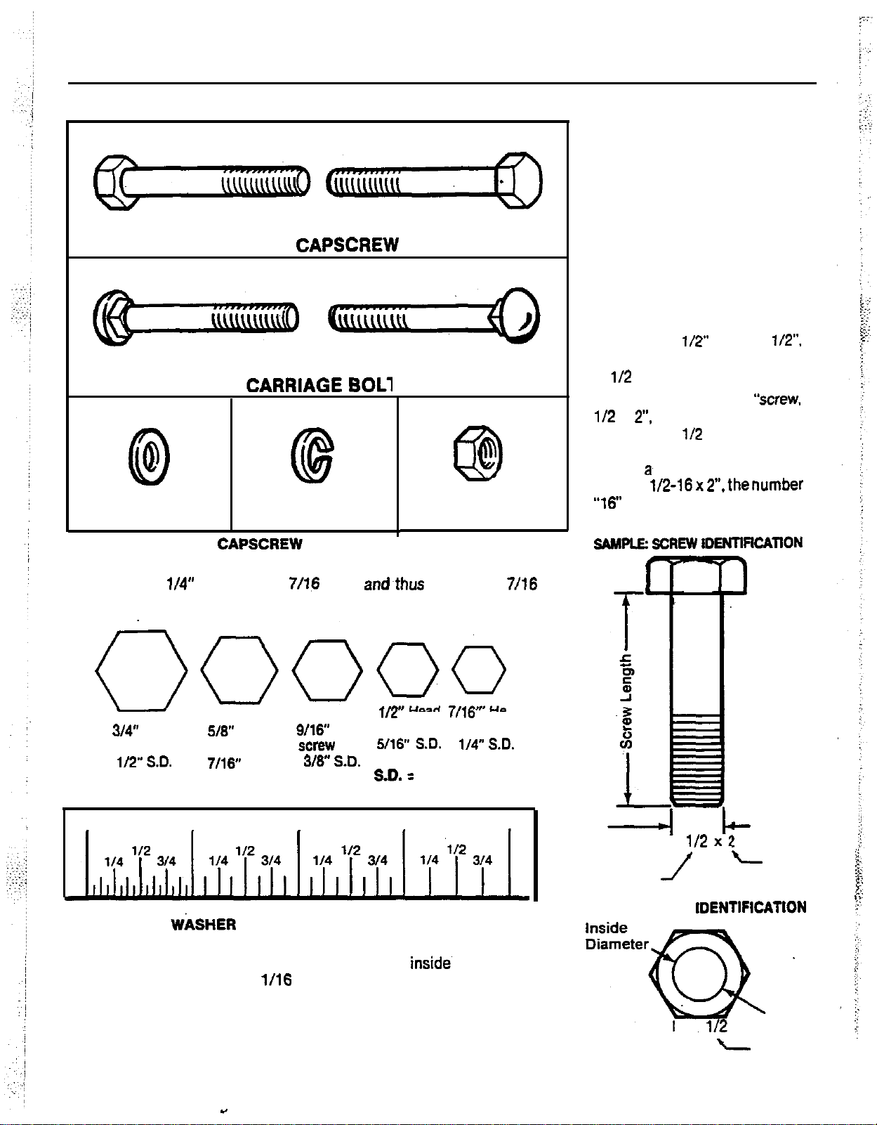
HEX CAPSCREW
p.
a
PLAIN WASHER LOCKWASHER
HEX CAPSCREW IDENTIFICATION
Shown below are actual size hex heads for standard screw sizes.
Example: a
wrench. To measure length, use the scale below.
l/4”
screw has a
7116
head and.thus requires a
NUT
7716
STANDARD
FASTENER
IDENTIFICATION
CHART
Hardware sizes are given in the
illustrations throughout this
manual.
If a washer or nut is identified
as “washer.
this means the inside diameter
is
l/2
inch.
If a screw is identified as
l/2
x
2”.
diameter is
shaft of the screw is 2 inches
long. If
“screw.
“16”
means that the screw has
16 threads per inch.
SAMPLE: SCREW iDENllflCAllON
l/2” or “nut.
this means the shaft
l/2
inch and the
a~
screw is identified as
l/2-16~2”.thenumber
-
172”.
‘Wrew.
3
~0000
34”
Head
screw with screw with
112”
SD.
0
Place the washer or nut on the above scale to
determine inside diameter. The actual
ameter can vary
comparison.
518”
7116”
1
WASHER AND NUT IDENTIFICATION
Head
S.D.
l/16
t/2” Heed 7fl6” Head
6716”
Head screw with screw with
screw
with
310”
SD.
2 3
inch. Use the scale for
5716”
SD. l/4” SC.
SD. =
Shaft Diameter
insides
di-
c
4
Screw
Shaft
Diameter
SAMPLE: NUT IDENTlFlCATlON
1
l/2
Nut.
112
Shaft
!
Diameter
c
Screw
Length
-
Inside
Diameter
ir
.$J
*.y
‘:i
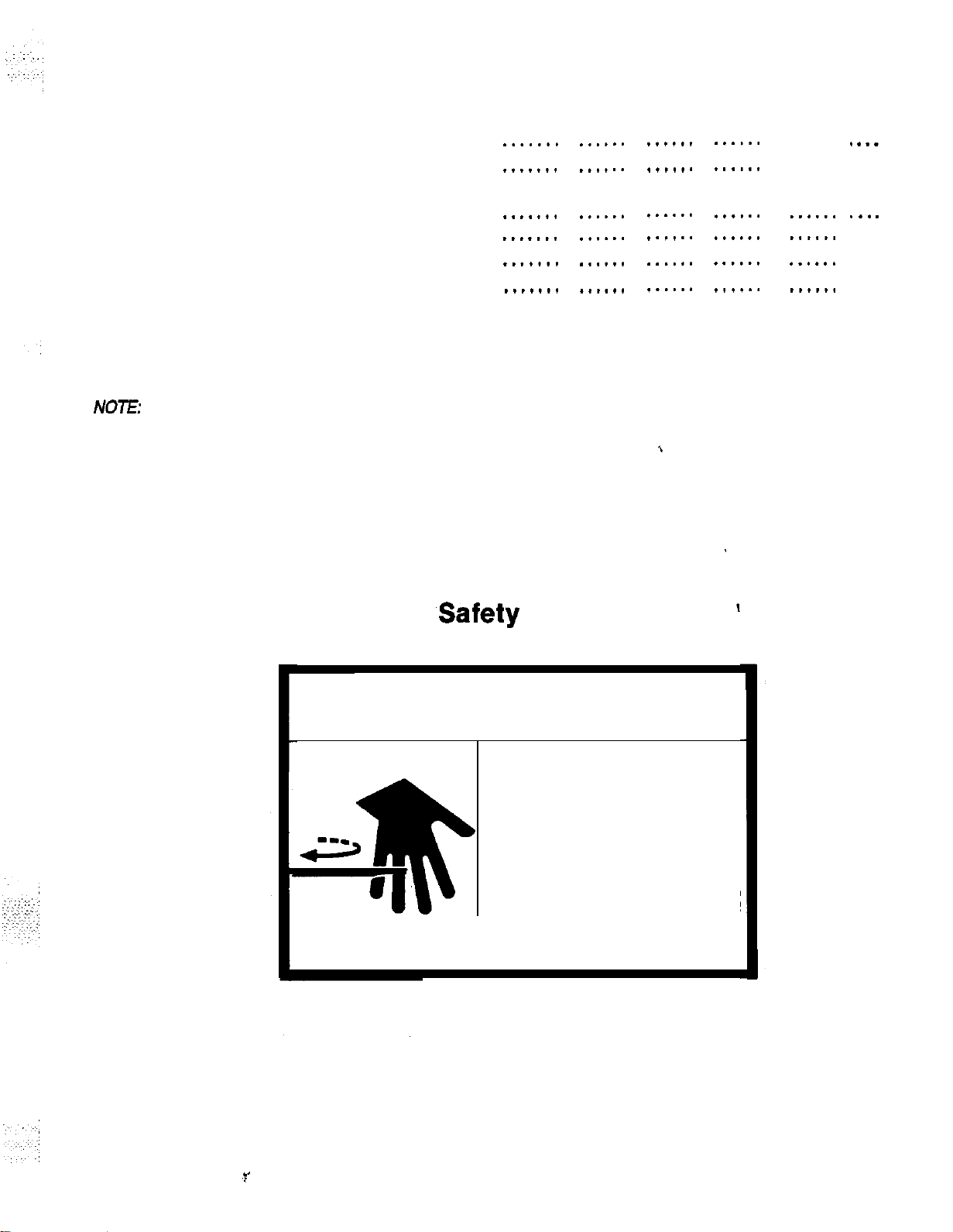
Table of Contents
Safety Decal ................................
Safety Rules
Installation
Lawn Tractor
Front-Cut Rider .........................
Operation
Standard Fastener Identification Chart
NOE
this reason, a replacement roller is supplied with the turbo blower kit.
The additional weight of the turbo blower may cause the end roller on the mower deck to wear faster. For
................................
...........................
..................................
.......
.......
.......
.......
.......
.......
.......
......
......
......
......
......
......
......
......
......
......
......
......
(I
......
......
......
......
......
......
......
......
......
......
. . . .
. . . . 2
. . . .
. . . .
. . . .
13
. . . .
15
1
3
8
A
DANGER
Located on Blower Housing
,Safety
ROTATING BLADES
SHUT OFF MOWER
AND TRACTOR
BEFORE SERVICING
OR CLEANING BLOWER
AND MOWER.
Decal
1
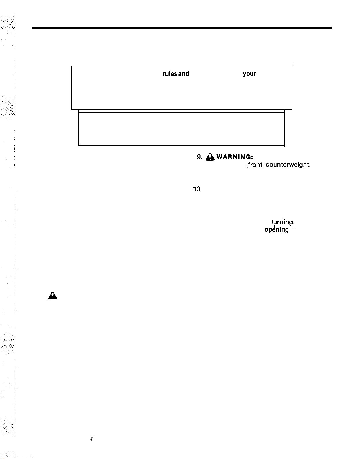
Safety Rules
Read these safety rulesand the safety rules in
Manual and follow them closely. Failure to obey these rules
A
could result in loss of control of vehicle, severe personal injury
to yourself, or damage to property or equipment. The triangle in the
text signifies important cautions or warnings which must be followed.
WARNING
A
When blower assembly is removed from mower deck, the deflector
must be installed as described in Operating Without Collection System.
1.
Know the tractor or ridercontrolsand how
to stop quickly. READ THE OWNERS
MANUAL.
2. Disengage the PTO, shut the engine off
and wait for all moving parts to stop before
attaching, adjusting, or disconnecting any
part of the collection system.
3. Check the collection system to make sure
it is bolted tightly to tractor or rider.
4. Check the latch handle to make sure it is
engaged so the dump cart’s box is locked
to the frame.
5. Look behind to make sure the area is clear
before backing up.
6. DO NOT turn sharply when the tractor or
rider is alongside a building or any object.
7. DO NOT carry passengers in the cart.
8.
A
CAUTION: For added tractor or rider
stability and to prevent tipping or loss of
control;
a. Use reduced speed on uneven ground
and when turning corners.
b. Reduce loads on hillsides. It is rec-
ommended that the collection system
be kept only half full when negotiating
any slopes. Start mowing on slopes
when the collection system is empty.
c.
Mow up and down the face of slopes;
never acrossthe face of any slope.
yo,ur
Operator’s
9. AWARNING:
slopes, use
operate on slopes greater than 30%
(16.7”).
10.
ACAUTION: Objects may be thrown
from mower.
For your safety:
a. DO NOT remove the cover while the
mower blades are tyrning. Shut off the
engine before openmg the door or
removing the grass chute.
b. Be sure the complete collection
system is in place (cover secure and
grass chute connected) before
operating the mower.
c. DO check the twin bag cover fre-
quently for wear and tear. Replace with
new cover for safety protection.
11. For best results when mowing grass: Set
the mower to cut from 1 to 2 inches of
grass. If grass isexceptionallytall, set your
mower as high as possible for first cutting.
Lower cutting height at succeeding
cuttings until proper height is reached. It
may be necessary to mow tall grass at a
slower tractor speed.
When operating on
,front
countennreight.
Never
installation - Lawn
,Tractors
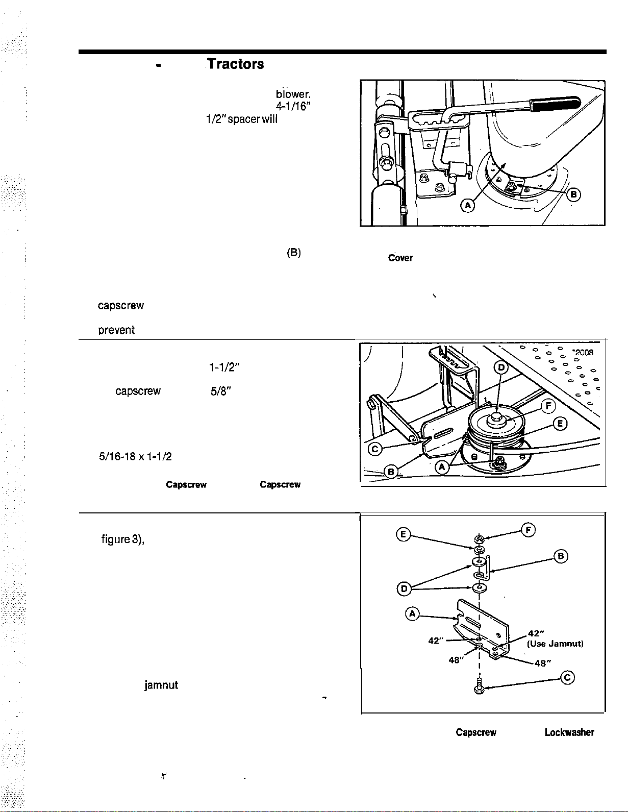
NOTE
Two spacers are packaged with turbo biower.
Installation on tractor requires use of
spacer (see step 11); the
1/2”spacerwill
4-l/16”
not be
used.
1. Remove mower deflector and arbor cover as
follows:
a. Remove the mower deflector by removing
two carriage bolts, lockwashers and nuts.
Install this hardware on the deflector for use
when blower is removed for side discharge.
b. Remove the right hand arbor cover (A, figure
1) by removing washers and nuts in frontthat
hold cover to deck. Also, remove nuts
(8)
and
washers that secure rear tabs to arbor.
2. Slip mower belt off the right hand pulley.
Remove the pulley from the arbor by removing
capscrew
(D, figure 2) and washers (F). Save
washers for reinstallation. Use wood block to
orevent blade from turning.
NOTE
Later model decks have
l-1/2”
taptite screws,
rather than 1” taptite screws, location A, figure
2. If
capscrew protrudes 5/S” above arbor, new
capscrews do not need to be installed
3. Remove brake spring or spring anchor (if
equipped) and two taptite screws from arbor at
locations A, figure 2. Replace these with two
5/16-18x l-1/2 capscrews (A).
Figure 1.
A. Arbor Cover
B. Nut dover
D.
A.
capscrew
B. Arbor Bracket E. Belt Stop, Front
C. Notch F. Washers
capscrew
4. Before installing arbor bracket (B, figure 2 &A,
figure3),
removewasherfrom underneath blade
brake bracket (rear capscrew). Arbor bracket is
same thickness as washer and will replace
washer. Loosen the front flange nut and remove
the rear flange nut on the blade brake bracket.
NOTE
Rear belt stop should be installed facing inside
of deck.
5. Install the arbor bracket (A, figure 3) and rear
belt stop (B) as shown. Note the different holes
for the 42” and 43” mowers. On the 42” deck,
install a
jamnut
at rear bracket location instead
of flange whiz nut. Tighten nut (F) snug only -
belt stop will be adjusted in step 8.
3
Figure 2.
I.
Figure 3.
A Arbor Bracket C.
B. Belt Stop D. Large Washers
CapSxew
E.
Lockwasher
F. Jam Locknut
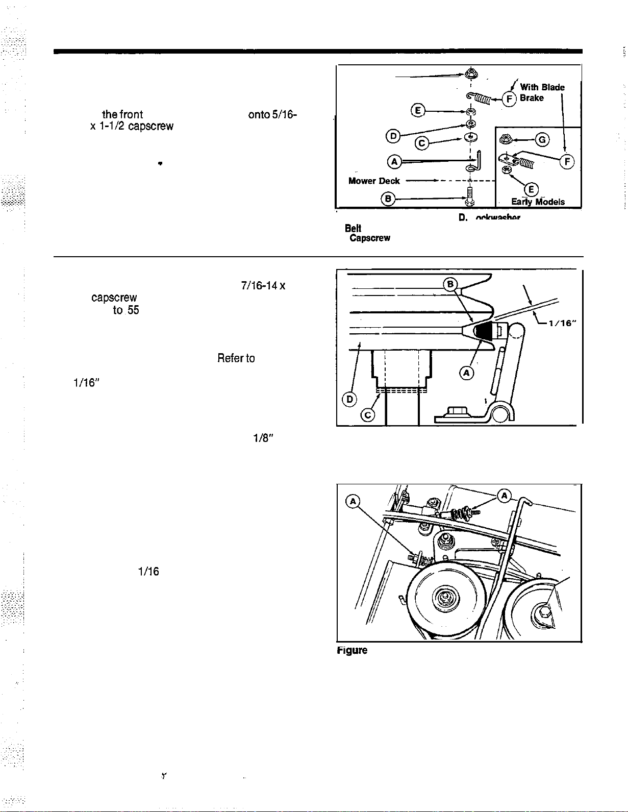
NOTE
Front belt stop should be installed facing
outside of deck.
‘6. Install
thefront
18 x l-1/2
shown. If removed, reinstall brake spring or
spring anchor (F) before flange nut(G). Tighten
nut (E) snug only
step 8.
belt stop (A, figure4)
capscrew
(installed in step 3) as
-
belt stop will be adjusted in
onto5/16-
G Mower Decks
7. Install new double-groove arbor pulley (D,
figure 5) with hub down. Use new 7/16-14 x 2-
1/4
capscrew
Torque
prevent blade from turning. It may be necessary
to add washer(s) (C, figure 5, two provided)
underneath the new pulley to properly align
brake pad and bottom groove. Referto figure 5.
Add washers to adjust top-to-bottom alignment:
l/16” clearance must be adjusted after belt is
installed and PTO is engaged.
8. Slip the mower drive belt onto the lower groove
of the new pulley (D, figure 2). With the mower
PTO engaged, adjust the belt stops
belt. Tighten the hardware.
9. If mower is equipped with blade brake, adjust
the brake after installing new double groove
pulley as follows:
a. Engage the PTO lever. Be sure that mower
drive belt tension is correctly adjusted (see
Operator’s Manual).
b. Inspect the brake pad (A, figure5) to V-pulley
(B) clearance. With PTO engaged, clearance
should be
c. If adjustment is required, turn adjusting nuts
(A, figure 6) until proper clearance is
reached.
and washers removed in step 2.
to~55
to 70 ft. Ibs. Use wood block to
l/l6
inch as shown in figure 5.
l/8”
from
Figure 4.
a
Belt
stop
B.
Capscrew
C. Large Washer
Figure 5.
A. Brake Pad
B. Bottom Groove
D.
,
n**.“rchn*
E. Nut
F.
Spring or Spring
G. Flange Locknut
C. Washers (If required)
D. Double-Groove Pulley
Anchor
Figure
6.
A. Blade Brake Adjustment Nuts

10. The baffle (A, figure 7) is installed in the blower
housing for use with 42” mower. For use with
48” mower, remove the baffleand install in holes
marked 48”.
I
Figure 7.
A Battle
: . . . . -..._
NOTE
On42”and 48” mowersthecapscrewinstalled
in next step is used in the hole occupied by a
screw held in place by a retaining nut. (This
screw secured the right-front corner of the
arbor cover.) Remove this screw(s) from
mower deck by tapping out with a hammer or
prying off the retaining nut.
11. Install the pulley cover (B, figure 8) with
hardware shown, items E through M. (Figure 8
shows blower housing but it is not installed at
this point of the procedure.)
In
A. Blower Housing
q
. Pulley Cover
C. Hook
D. Clip
E.
Capscrew
F. Washer,
G. Large Washer, 5/16
H. Spacer
I.
Lockwasher, S/16
J. Nut. 506
K.
La&
L. Large Washer, 5/16
M. Locknut, S/16
N. Wing Nut
5
Washer, S/16
5116
I

12. Install wing nut (D, figure 9) as follows:
a. Remove existing hardware from front end of
stone guard.
b. From inside deck, install new
5/16-18 x
carriage bolt (F, figure 9). Then install the cup
(A), 5/16 lockwasher (6). and
506
Tighten the nut.
c. Thread the wing nut (D) far enough onto the
screw so that the 5/16 locknut (E) can be
threaded on flush with the end of screw.
2-l/4
nut (C).
Figu’ie
9.
A. cup
q . Lockwasher,
C. Nut.
5116
5116
Q. Wing Nut
E. Lrxknut,
F. Carriase Bolt
5116
13. Install the new baffle (A, figure 10) in deck on
stone guard using existing hardware. Hardware
may be installed with nut to inside or nut to
outside.
Figure 10.
A. Battle
B. Carriage Bolt
C. Mower Discharge
14. Install the blower assembly as follows:
a. Pivot cover (B, figure 8) away to expose the
arbor.
b. Align the notch (G, figure 11) with spaceron
arbor bracket. Align spacer(C) with notch
(C,
figure 2) on arbor bracket. Slide theassembly
into place as shown in figure 13, while
aligning front notch between cup and wing
nut (D, figure 13). Tighten wing nut.
Figure 11.
A. Blower Drive Belt
B. Idler Pulley C. Space
D. Belt Retainer
E. Baffle
F. Driven Pulley
G. Notch
Omening
Hdok
Over Stone Guard
B&e
6
6

c. Place mower in low cut position. Raise the
flap (A, figure 12) and push on the belt
retainer (E) to obtain slack in the belt. Install
the blower drive belt (D) in the top groove of
the pulley(B).
d. Rotate the pivoting cover (A, figure 13) into
place and attach the hook (B) to the clip (C)
on the housing.
Figure 12
A. Flap
6. Pulley
c.
Ben
D. Drive Belt
E. Belt
Retainer
\
Figure 13.
k
pdley Cover
9.
Hook
C. Clip
D. Wing Nut
7

Installation - Front Cut Riders
NOTES
1. Two spacers are packaged with the turbo
blower. Installation on the Front-Cut Rider
requires use of the
The
4-l/16”
2. The replacement right hand belt cover (seestep
15),along
for the right hand idler pulley (see step
packaged with the collection system.
INSTALLATION
1. Remove right hand mower belt cover by
removing flat washer and flange nut (A) and
front taptite screw (B). Loosen hardware at
center location (C). Belt cover can bediscarded
as new belt cover and arbor cover will replace
original cover. Save all hardware for installing
new cover.
2. Remove the deflector mounting hardware and
reinstall in deflector for future use. Deflector
must be reinstalled if turbo blower is removed
from mower deck.
spacer will not be used.
with
l/2”
spacer (see step 14).
thenew3/8-16x2-1M”capscrew
4)
is
Figure 1. (Later
A. Flange Nut
B. Tapttle Screw
C. Mounting Hardware - Center Location
Mode\1
Shown)
WARNING
e
Use caution when moving spring-loaded idler
pulley. Spring tension isstrong. Do not remove
belt from spring-loaded idler pulley. Remove
belt from left and right hand pulleys.
I
3. Pull spring-loaded idler pulley away from belt
and remove belt from right hand arbor pulley
and idler pulley.
4. Remove the idler pulley
from the top) and install new 3/8-16 x
capscrew
mounting hardware may need to be loosened to
install 2-l/4”
existing flat washer
existing flat washer(B),
(D) to secure capscrew. Install large washer(E)
onto capscrew.
nut (D), and large washer(E) are packaged with
the collection system.
Existing flange nut will be used in step 15 to
secure new belt cover.
from the bottom. Pulley bracket
capscrew
(8)
Capscrew
NOTE
capscrew
(A) from bottom. Install
on top of bracket, pulley,
lockwasher(C),and
(A), lockwasher (C),
(installed
2-114”
nut
,
F
igure 2.
A.
2-114” Capscrew
B. Flat
C.
D. Nut
Washer (Existing)
Lockwasher
E. Large Flat Washer,
13/X? x l-l/2X 118
-
Pulley
I

6.
Remove the capscrew, lockwasher, and flat washer
securing right hand arbor pulley. Retain the washers
for reinstallation (step 9). Use a wood block to
prevent blade from turning.
SunRunnerNanguard
6. On early models without bet stop (A, figure 3)
remove two self-tapping screws from arbor and
install two
Parts will be installed on these capscrews in steps 7
and 8 as shown in figures 3 and 4.
7. Install the bracket (F, figure 4) with hardware as
shown in figures 3 and 4. On early models, install the
rear belt stop (C) facing the inside of mower deck as
shown in figure 4. Use washers (B & D) and
lo&washer (H) only for securing belt stop (C) on
early models. Use jam nut at locations A and E.
8.
On early models, install the front belt stop (D, figure
3) onto front
washer,lockwasher,andnut.Tightensnugonly.The
beL
stop should face the inside of mower deck as
shown in figure 3.
.5/l
6-18 x
Models
l-1/2”
capscrew
capscrews (A, figure 3).
(installed in step 6) with
Figure 3. (Early Model)
A.
capscrews, l-112’
B. Rear Mounting Bracket
Figure 3A. (Later Model)
A. Ben Stop (Existing)
B. Rear Mounting Bracket
C. Rear Belt Stop
D. Front Belt
Stop
FCll3OO Models
6. On later models with
figure
3A), it is not necessary to change capscrews
as new belt stops are not required.
7. install the bracket (F, figure 4) with hardware as
shown in figure 3A and 4. Use
4) to secure bracket (F).
factoty-installed belt stop (A,
jamnuts (A & E, figure
9
Figure 4.
A. Jam Locknut,
B. Washer,
c.
Beit
stop
D. Washer,
E. Jam Locknuf
F. Arbor Bracket
5/16
5116
5116
5116
(A,
figure 3A).
G.
Capecrew, 6116-18 x l-112
H. Lockwasher, 5/16
I.
spacer
J.
Washer,
K. Screw, Self-Tapping, I/4-20
L. Left-Hand
spaal
Mtg. Hole
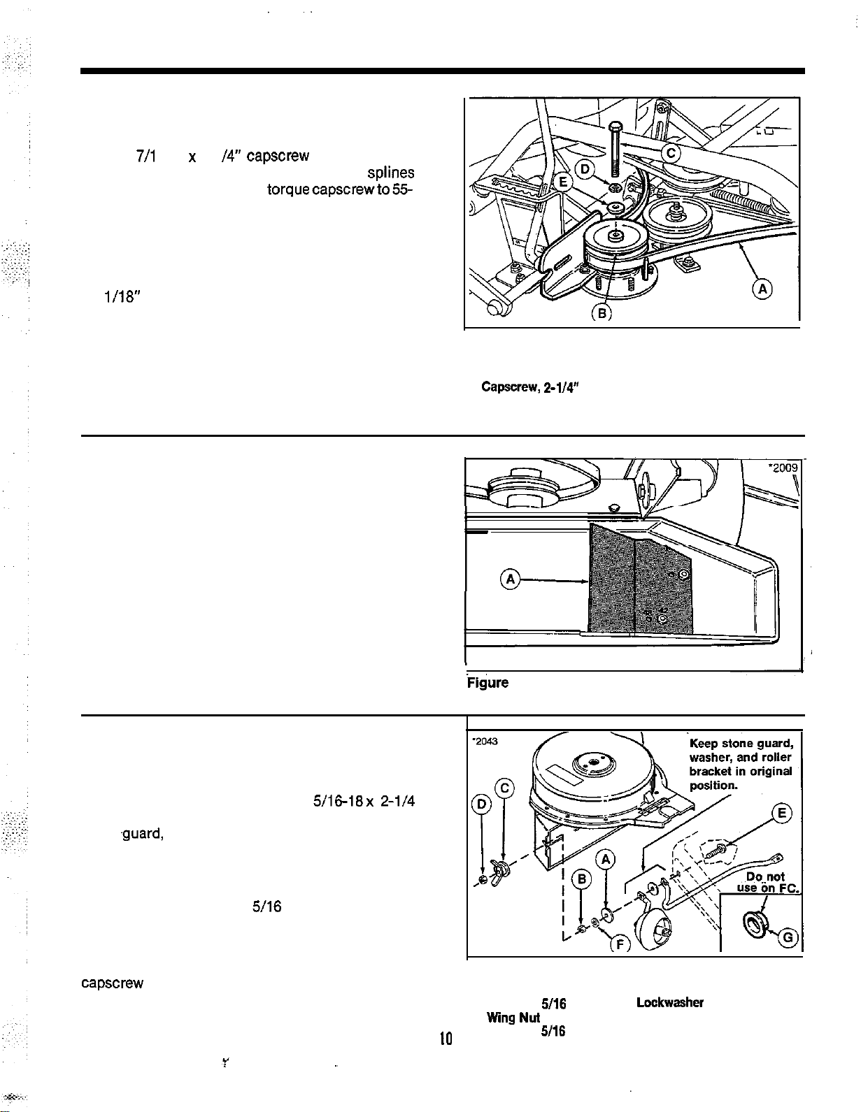
9.
Slip the mower drive belt (A, figure 5) around the
bottom groove of double-groove pulley (B).
Install pulley with hub down and secure with
new
7/l
6-14 x 2-l
/4”
capscrew (C) and washers
(D and E) removed in step 5. Make sure splines
arecorrectlyalignedand torquecapscrewto55-
60 ft. Ibs. Use a wood block to prevent the blade
from turning.
10. Reinstall the mower drive belt by pulling on the
spring-loaded idler pulley to provide slack in
belt. With belt installed, adjust the belt stops
l/18”
from belt and tighten mounting hardware.
11. The baffle (A, figure 6) is installed in the blower
housing for use with 42” mower. For use with
48” mower, remove the baff le and install in holes
marked 48”.
Figure 5.
A. Mower Belt
B. Double-Groove Pulley
C.
Capscrew, Z-114”
D. Lockwasher ,
E. Flat Washer
-
12. Install wing nut assembly as follows:
a. Remove existing hardware from front end of
stone guard.
b. From inside deck, install new
5/16-18x 2-l/4
carriage bolt (E, figure7) through deck, stone
.guard,
washer, and roller bracket. Then
install the large washer (A), lockwasher (F),
and nut (B).
c. Thread the wing nut (C) far enough onto the
screw so that the 5/16 locknut (D) can be
threaded on flush with the end of screw.
NOTE
On front-cut riders, do not install cup (G) onto
capscrew to retain blower housing. Cup is used only
for tractor applications.
IO
I
Figure
6.
A. Baffle
Figure 7.
A. Large Washer
B. Jam Nut,
C.
Wing
D. Locknut,
5/16
Nut
5116
E. Carriage Bolt
F.
Lockwasher
G. Cup

13. Install the new baffle (A, figure 8) in deck on
stone guard using existing hardware. Hardware
may be installed with nut to inside or nut to
outside.
14. On new arbor cover, install on top of weld
figure 9) the largest washer (B
spacer (C), lo&washer(D), and nut (Q as shown in
figures.
in next step).
15. On
reusing front taptite screw (G) removed in step 1.
Install flat washer (I) and flange nut
step 4) to secure belt cover. Tighten flat washer and
flange nut (H) loosened in step 1.
(Largeflatwasher(F) shownwillbeinstalled
2-l/2” idler cover bolt, install
l-i/Z”
O.D.),
beit
cover to deck
(J,
removed in
bolt
(A,
l/2’
H&k 8&fle
Over Stone Guard
‘igure 8.
a Baffle
s.
Carriage Bolt
C. Mower Discharge Opening
6
Figure 9.
A.
Weld Bolt
8. Large Washer,
C. Spacer,
D.
Lockwasher
E. Nut
F. Large Washer
0. Taptite
H. Center Hardware
I.
Flat Washer
J. Flange Nut
112”
Screw
11
I-112”
O.D.
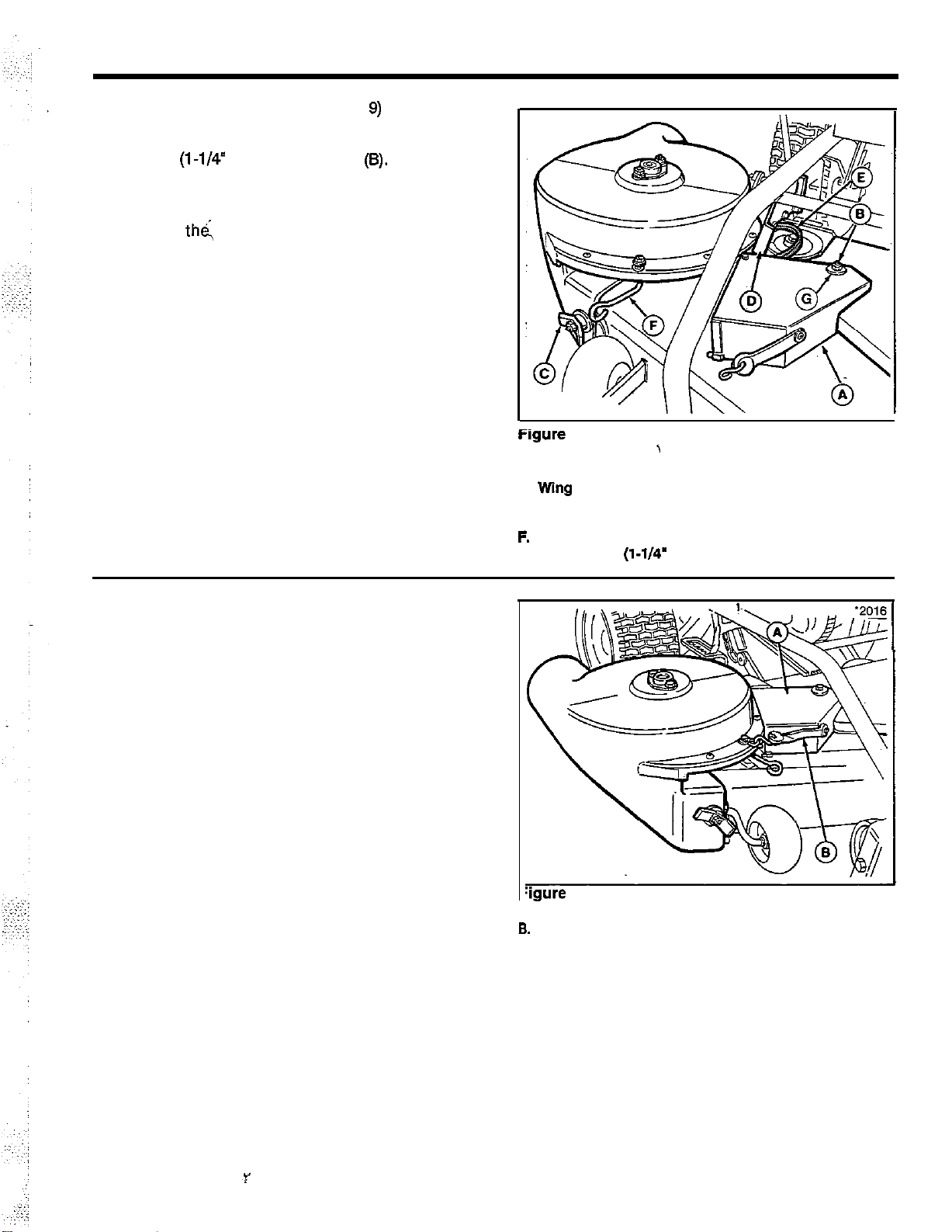
16. Make sure that flat washer (F, figure 9) is on top of
spacer assembly and install new arbor belt cover (A,
figure 10) as shown in figure 10. Secure with flat
washer (l-1/4” O.D.) and locknut
should be free to pivot.
17. Install the blower assembly as follows:
a. Align th& notch on blower assembly with
spacer on arbor bracket. Align spacer on
blower assembly with notch on arbor bracket.
Slide the assembly into place as shown in
figure 10 while aligning front notch between
cup and wing nut. Tighten wing nut (C, figure
10).
b. Raise the flap (D, figure 10) and install the
blower drive belt (E) in the top groove of the
pulley. Push on lever (F) to provide slack to
install belt.
NOTE
On later models with single (front) belt stop,
belt stop must be on outside of both mower
belt and turbo belt.
(8).
Belt cover
Figure
10.
A. Arbor Cover
B. Locknut
C.
Wing
Nut
D. Flap
E. Blower Belt
F.
Lever
G. Rat Washer
(l-1/4’
’
O.D.)
18. With belt installed, pivot arbor cover (A, figure
11) into position as shown in figure 11. Secure
with rubber strap (B) to blower housing.
:igure
11.
A
Arbor Cover
8.
Rubber Strap
12

Operation
WARNING
A
For safety reasons, grass and debris should
not be removed from any
collection system until engine is shut off, key
removed, and all moving parts have stopped.
I
WARNING
A
Before raising cart or twin-bag cover, shut off
engine, remove key, and set parking brake.
OPERATING WITHOUT COLLECTION SYSTEM
part
of turbo or
BEFORE OPERATION
Clear the lawn of all sticks, stones, wire and other
debris which maybecaughtorthrown bythemower
blades.
Clean the tube with mild detergent (other products
may damage tube). The flow of grass can be seen
I
through the tube while moving.
Check grass condition. If wet, wait until later in the
day. If grass is wet plugging may occur.
For -efficient bagging, air circulation under the
mower deck, through the chute and into the bag is
very important. For this reason, you should remove
grass and debris from underside of mower deck,
discharge chute and cover.
The tube and elbow can be removed
for cleaning. ,
asan assembly
When blower assembly is removed
mower deck. the deflector must be installed as
described in this section.
1. To operate without the grass collection system,
remove the blower assembly by loosening the
front wing nut on blower housing and slipping
belt off of the pulley. Reinstall the mower
deflector (figure 1) and the original hardware.
Install two carriage bolts from bottom and install
washers and nuts (A). Install the front washers
(8) and nut (C). Be sure flat washers and
lockwashers are used at all three locations.
2. Pivotthecover(A,figure2)
and hook rubber strap into the notch (C) on the
arbor bracket.
overthearborpulley
from
1
1
Figure 1.
A. Nut
6. Washer
C. Nut
A. cover
S.
Rubber Strap
C. Notch
Figure 2. Front Cut Rider Shown
13


i

.:::).‘,:,::::
~._,,
,
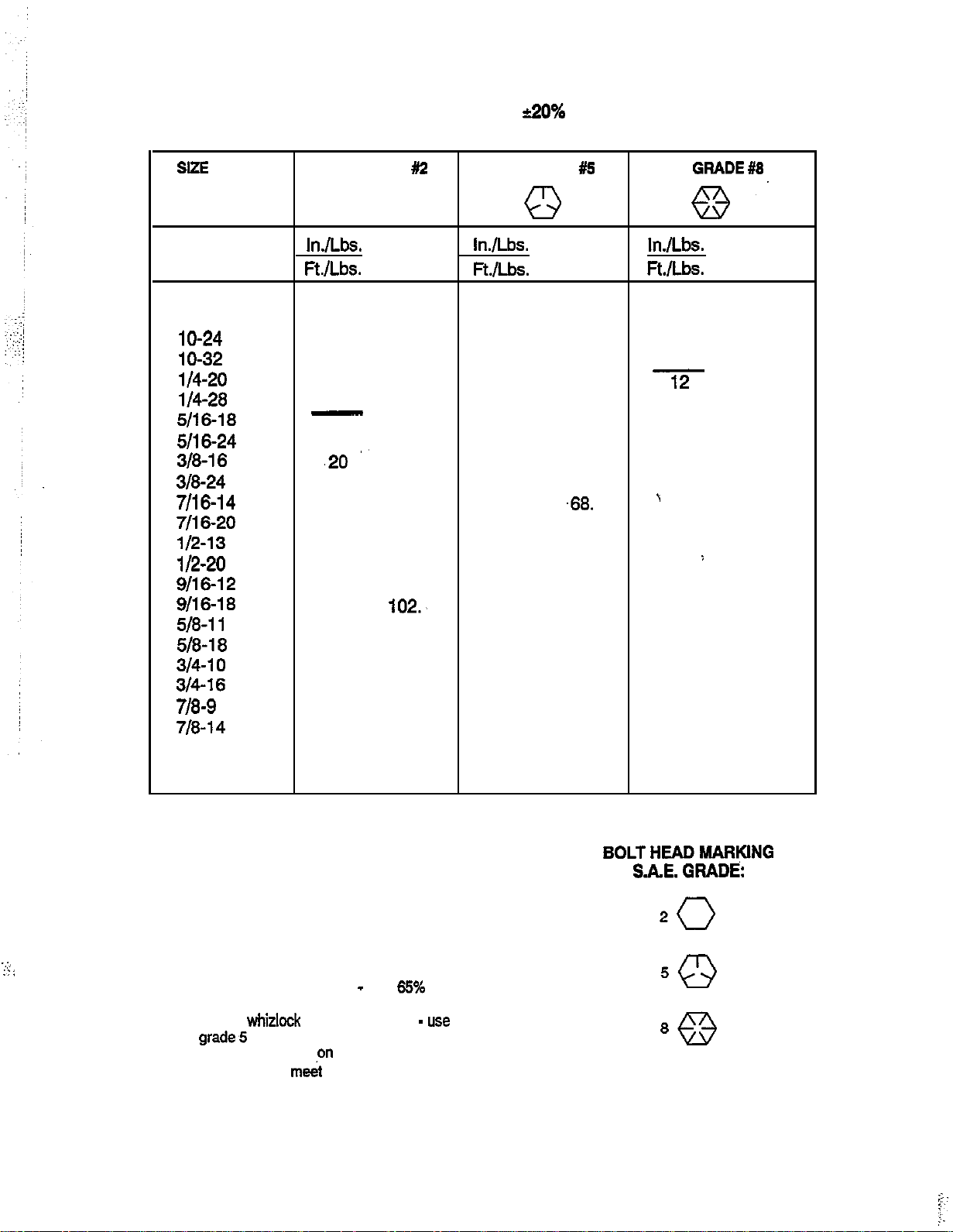
TORQUE SPECIFICATIONS FOR
STANDARD MACHINE HARDWARE
TOLERANCE
+200/o
SIZE
8-32
8-36
lo-24
lo-32
l/4-20
l/4-28
5116-18
5116-24
318-16
318-24
7116-14
7116-20
l/2-13
112-20
9116-12
9116-18
518-11
518-18
314-10
3/4-16
718-g
718-14
1-8
1-12
SAE GRADE #2 SAE GRADE
0
InJLbs.
Ft.lLbs.
Nm.
19
20
27
31 3.5
66
76
11
12
,,
,20
'23
30
35
50
55
65
75
90
100
160
180
140
155
220
240
In./Lbs.
Ft./Lb.s.
2.1
2.3
3.1
7.6
8.6
15.
16.3
27.2
31.3
40.8
47.6
68.
74.8
83.4
102.,
122.4
136.
217.6
244.8
190.4
210.8
299.2
326.4
Q
Nm.
30 3.4 41 4.6
31 3.5
43 4.9
49 5.5
-8 10.9
10 13.6
17 23.1 25 34.
19 25.8
30 40.8 45 61.2
35 47.6
50
55 74.8 80 108.8
75 102. 110 149.6
90 122.4
110 149.8
120 163.2
150 204. 220 299.2
180 244.8 240 326.4
260 353.6 386 525.
300 408. 420 571.2
400 544. 600 816.
440 598.4 660 897.6
580 788.8
640 870.4
A15
.68.
SAE
GRADE #8
8.
InAbs.
Ft.Rbs.
43 4.9
60 6.8
68 7.7
12
'
1,000 1,360.
16.3
14 19.
25 34.
50 68.
70 95.2
i
120 163.2
150' 204.
170 231.2
900 1,224.
Nm.
,
..:,,
:::
NOTE:
1. These torque values are to be used for all hardware
excluding: locknuts, self-tapping screws, thread
forming screws, sheet metal screws and socket head
setscrews.
2. Recommended seating torque values for locknuts:
a. For prevailing torque locknuts
torques.
b. For flange whizlock nuts (and screws) -
of grade,5 torques.
3. Unless otherwise noted
torque values must meet this specification.
-
use 65% of grade 5
usa
135%
on assembly drawings all
BOLTHEADMARKING
S.A.E.GRADE:
20
 Loading...