

Page 1
INSTALLATION
INSTRUCTIONS
KIT PARTS
DUAL TAIL WHEELS KIT
Mfg. Nos. 1691852
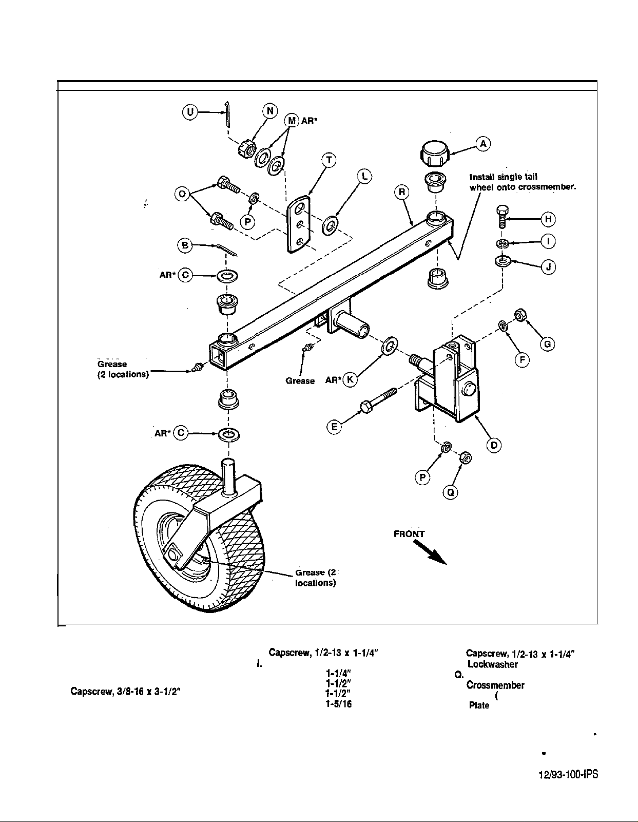
Figure 1.
A. Plastic Cap
B. Cotter Pin
C. Washer
D. Support Bracket
E.
F. Lockwasher
G. Nut
3/E-16
AR’ = As Required
H.
J. Flat Washer, l-1/4” O.D.
K. Flat Washer, l-1/2” O.D.
L. Flat Washer, l-1/2” O.D.
M. Flat Washer,
N. Castle Nut
l-1/4”
0.
P.
R.
S. Wheel
T.
U. Cotter Pin
112-n
Assembled)
FORM - 170X147-02
I-114”
PRINTED IN U.S.A.
Page 2
INSTALLATION
1. Jack up rear frame and support rider with
wooden blocks or jackstands.
2. If 60 gallon grass catcher is to be installed,’
remove weights and mounting hardware from
rear frame. Retain hardware and reinstall
whenever grass catcher is removed.
3. Remove plastic cap (A, figure I), cotter pin (B),
and washers (C) securing rear wheel. Retain
hardware to reinstall wheel onto new
crossmember.
4. Install
through rear frame and secure with 3/8-16x 3-
1/2”
on top of frame. Spread uprights of support
bracket as required to install to rear frame,
5. Install 1/2-13x 1-1/4”capscrew (H),lockwasher
(I), and large flat washer (J,
I.D.) through threaded spindle.
6. Install two washers
support bracket spindle (more may be
necessary) and install crossmember (R)
spindle. While holdingcrossmemberfirmlyonto
spindle, rotate crossmemberfromside
there is not at least
add additional washers (K,asrequired) between
crossmember and support bracket.
O.D., 1” I.D.) on
clearance with frame,
O.D.,
7
Place flat washer (L,
plate
Use washers (M) as required to fill up space on,
spindle. Tighten castle nut securely and then
back off until crossmember rotates freely.
Check that cotter pin (U) can be installed
through slot in castle nut. Loosen nut until step
is performed.
8.
In top hole of plate (T), install
on support bracket. In bottom hole, install
similar capscrew (0) and secure on backside of
support bracket with lockwasher (P) and
(Q). Tighten capscrews (0), castle nut (N), and
install cotter pin.
9.
Install washer (C,
wheel spindles and install through bushings on
each side of crossmember. On top side, install
that wheels rotate freely after cotter pins are
installed.
10. Install plastic caps (A) over wheel spindles.
11. Lubricate the five grease fittings (2 on wheels, 2
on wheel spindles, 1 on support bracket).
12. Adjust tire pressure to 20 psi (137
onto spindle and secure with washers,
O.D., 3/4” I.D.) and castle nut (N).
O.D., 1” I.D.) and,
O.D., 1” I.D.) onto
2
FORM
 Loading...