

Page 1
KIT PARTS
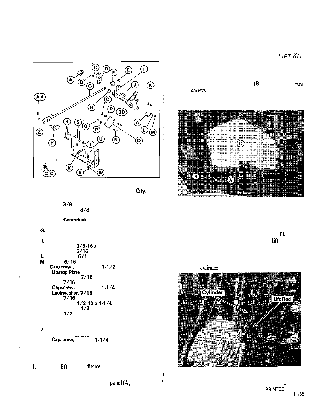
Figure 1. Kit Parts
Ref. Description
A. Searing
8.
Nut.
C. Lockwasher.
D. Lift Arm
E.
Nut,
F.
Trunnion, Rear
Lift Rod
H. Washer, 1
Lift Shaft
J. Capscrew,
K.
Capscrew,
Lockwasher,
Nut,
N. Caoscrew. 7/18-14x
0. upstop
P.
Lockwasher,
Cl. Nut,
R.
S.
T.
Nut.
U.
Capscrew,
V.
Lockwasher.
7/16-14x
W. Nut,
X.
Hitch
Y.
Trunnion, Front
Washer
AA. Clip
88.
CC. Washer, Special
7/16x
6
INSTALLATION
INSTRUCTIONS,’
REAR
MFG. NO. 1691765
c. Remove the tunnel cover
at rear and loosening left front screw.
d. Remove upper side panel (C) by removing three
screws. Retain the hood catch for reassembly.
2
2
2
1
1
1
1
1
1
1
2
2
2
2
1
1
2
2
4
4
4
2
2
2
1
1
1
1
1
1
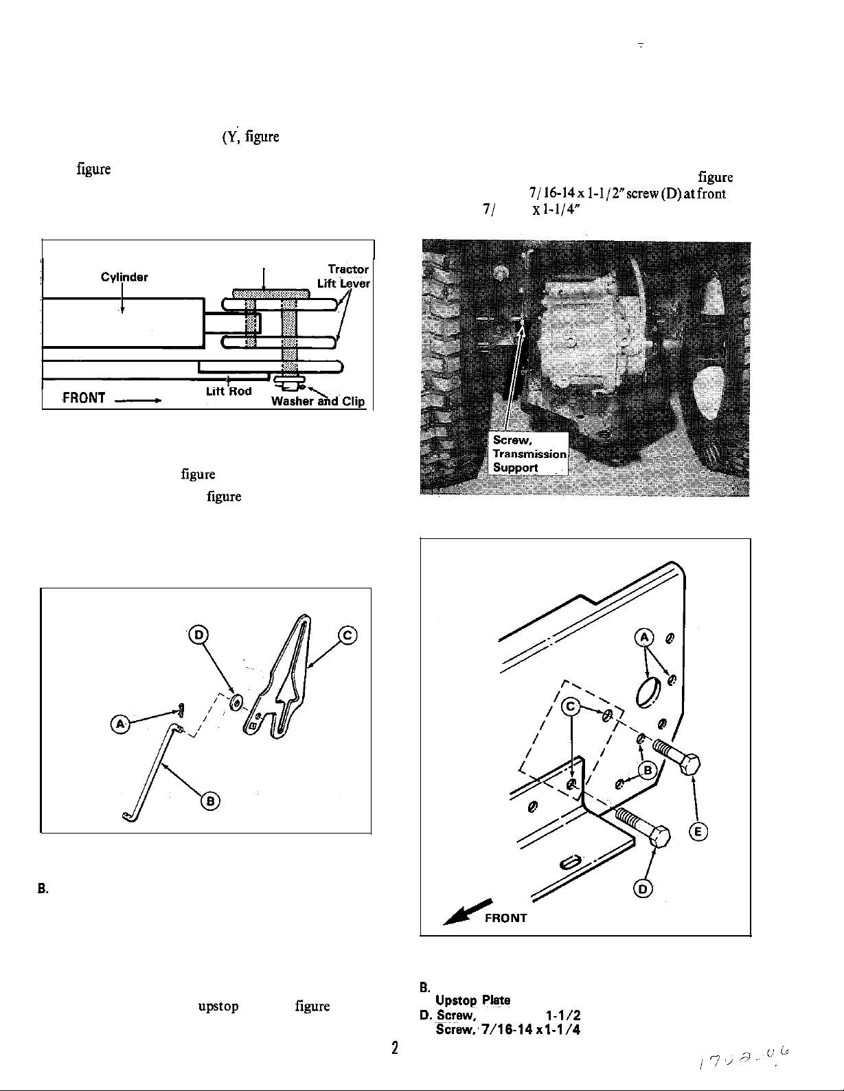
Figure 2.
A. Lower Side Panel
8. Tunnel Cover
C. Upper Side Panel
e.
Insert lift rod (G, figure 1) from rear of tractor up to
the tractor lift lever. The rear end of lift rod is
shown in figure 8. Figure 3 shows the
positioned in tractor.
f. The cylinder (figure 3) is connected to the tractor
lift lever. Remove the clip and pin, and disconnect
the
KIT
rod as it is
INSTALLATION
Install the
rod (G, figure 1 ) as follows:
a. Open tractor hood.
b. Remove the tractor lower side
right-hand side by removing four screws.
figure 2) on
Figure 3.
1
FORM
1702006
Page 2
g. Using the front trunnion
figure I), connect the
cylinder and lift rod(G) to the tractor lift lever. (See
4.) Position cylinder and insert short leg of
trunnion through it. Connect lift rod to long leg of
trunnion. Be sure lift rod is positioned with flat side
as shown.
VIEWED FROM TOP
Figure 4.
2. For 18 hp models, Mfg. No. 1691307, and older, install
special washer (CC,
a.
Remove cotter pin (A, figure 5) and remove ground
speed control rod (B) from cam plate (C).
b. Install special washer (D) on control rod (B).
Reinstall rod to cam plate and secure with cotter
pin.
a. Remove and discard the rear-most screw from the
transmission support (figure 6).
b. Install the plate in mounting holes (C,
shown. Use 7/16-14x 1-1/2”screw(D)atfront hole
and 7/ 16-14
screw (E) at rear hole. Install
lockwashers and nuts.
Figure 6.
VIEWED FROM LEFT SIDE
Figure 5. Special Washer Installation
A. Cotter Pin
Ground Speed Control Rod
C. Cam Plate
D. Special Washer
3.
If a rear PTO has been installed on the tractor, it is not
necessary to install the
install, proceed as follows:
Figure 7.
A. Lift Shaft Mtg. Holes
Hitch Mtg. Holes
C. Upstop
E. Screw;7/16-14x
Mtg. Holes
7/16-14x
Page 3

4. Insert the lift shaft (A, figure 8) into position, place
bearing (B) on to each end, and secure with capscrew
lockwasher and nut (C) on each side.
5. Position the rear tnmnion (D) onto
rod. Install
the lift arm half(E) to lift shaft(F) and secure with two
3/8-16x
(G). Install centerlock nut on end of lift rod.
7. From top, connect hitch~(A) to drawbarwith two
13
capscrews (C),
/Z” lockwashers, and
nuts.
8. Reinstall panels and cover removed in step 1.
Figure 8.
A. Lift Shaft
S.
C. Mtg. Hardware
D. Rear Trunnion
6. Position the hitch (A, figure 9) as shown and install
E. Lift
F. Lift Shaft
G. Mtg. Hardware
two 7/M-14~~ I-1/4”capscrews7/ 16”lockwasherand
(B) each side. See mounting holes (B, figure
Figure 9.
A. Hitch
S. Mtg. Hardware
c. Capscrew
 Loading...