

Page 1
i
;
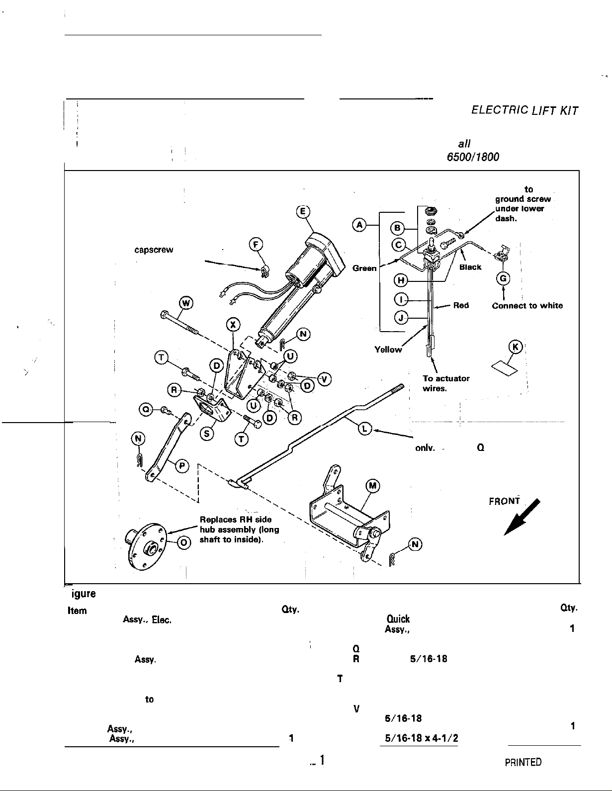
KIT PARTS
Mount to top
capscrew
support bracket.
on lift lever
~
~
INSTALLATION.,
~~~~~
INSTRUCTIONS
ELECTRlC
MFG. NO. 1691531
For use with a// mounted attachments
on
6500/1800 Series Tractors
Mount to
ignition wire.
L//=T KIT
~-
Fi
igure 1. Kit Parts
Item
A Harness
8 Switch, Electric 171883
C Wire, Switch to Ground
D Lockwasher
E Power Lift
F Clamp, Insulated 826818
G Connectors, Self-Stripping 1606761
H Wire, Switch to Ignition
I
J Wire, Switch to Lift
K Decal, Lift Switch 1669833
L Rod
M Arm
Description Part No.
Assy.. Elec.
Assy.
Wire, Switch to Lift 1702077
Assy.,
Lift 1701680
Assy..
lift 1701808
Lift 1702082
171868
1817366
1667764
1702075
1702076
my.
Used for rear attachments
onlv.
Use item Q for mowers.
FRONT
J
Item Description
1
1
1
;
4
1
1
1
1
1
1
1
1
1
1,
.-
N Pin,
0 Hub
P Link, Actuator
Q Pin, Pivot
R
S Bracket, Actuator, Front
1 Capscrew, Hex Hd..
u Spacer
”
W Capscrew, Hex Hd..
Quick
Assy..
Wheel
Nut, Hex.
Nut. Hex Lock,
5/16-18
5/16-18x 1
6/16-18
5,‘16-18 x
4-l/2
Part No.
1960033 3
1701914
1701881 1 ~
102004 2
1917372 4
1701878 1
1921333 4
1665699 3
1823362 1
1925892
FORM 1702100
PR,NTED IN U.S.A.
oty.
1
1
882
Page 2
WARNING
A
Before installing the kit or making any adjustments:
disengage the PTO; set the parking brake; stop the
engine and remove the key.
WARNING
A
When disconnecting the battery cables, always
disconnect the negative cable first. When
connecting cables, always connect the negative
cable last. The positive terminal can easily be
shorted to the frame with
Do not touch any wires or electrical components
such as the solenoid, unless the battery cables
INSTALLATION
1. Park tractor on flat, level surface. Turn tractor off.
Disengage PTO, and allow all moving parts to stop.
Engage the parking brake.
,2.
Disconnect the battery cables and position away
from terminals.
a
tool if this is not done.
are
Remove rear right-hand wheel assembly.
Remove tive
secure kit hub assembly (0, figure 1) to wheel. Do not
install on tractor.
Prepare template (provided on last page) by cutting
out all dashed areas. Use this template to drill five
1
l/32”
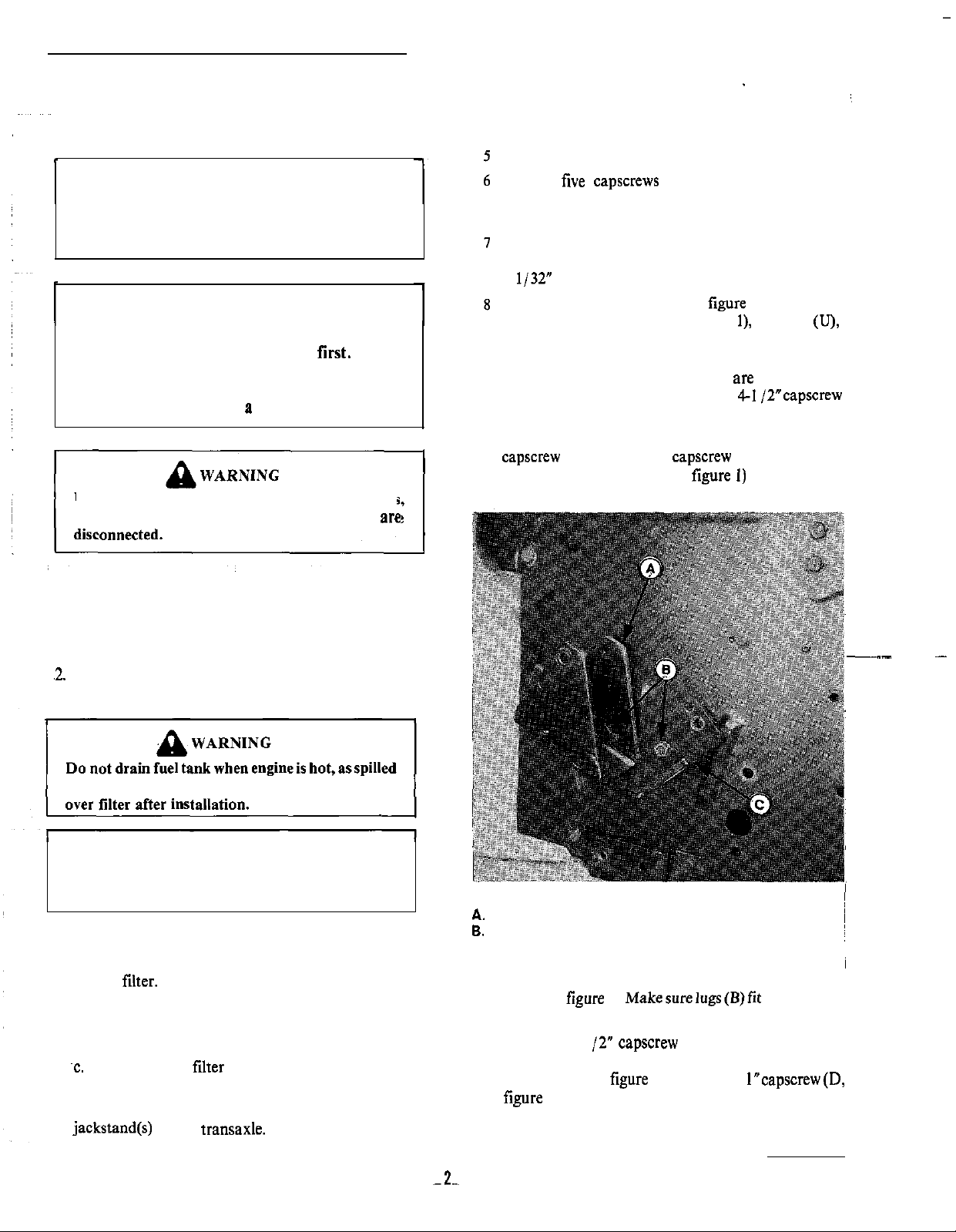
Install rear actuator bracket (X, figure 1 or A, figure
2) with two capscrews (T, figure l), spacers (U),
lockwashers (D), and nuts (R). Install bolts from
outside in, putting spacers between bracket and
wrapper. Lockwashers and nuts
inside of wrapper. Do not install the
(W) at this time.
9. Install front bracket (C, figure 2) with bottom
capscrew (B) only. Install capscrew from inside out.
,
Secure with lockwasher (D, figure 1) and nut (R).
capscrews
holes in wrapper.
from wheel assembly and
are installed on
4-I
/2”capscrew
.-
gasoline may ignite. Insure clamps grip hose firmly
WARNING
A
Handle gasoline with care. It is highly flammable.
Use an approved gasoline container.
3. Drain the fuel tank as follows.
a. Place an approved gasoline container below the
filter.
fuel
b. Use a pliers to spread the fuel filter clamps and
slide away from filter. Do not spread more than
necessary.
~c.
Pull hoses off filter and allow gasoline to drain
into container.
4. Raise rear right-hand side of tractor up and place
jackstand
under transaxle.
Figure 2. Bracket Installation
A.
Rear Bracket
6.
1” capscrews
C. Front Bracket
10. Insert cylinder (A, figure 3) through brackets as
shown in
rear bracket slots.
11.
Install top 4-l /2” capscrew (C) on rear bracket (with
spacer between bracket and wrapper) and secure
with locknut (V, figure I). Install top l”capscrew(D,
figure 3, from inside wrapper) in front bracket and
secure with lockwasher and nut.
figure 3.
Makesurelugs(B)fit
-,2.-
securely into
Page 3

Figure 3. Cylinder ~lnstallation
A. Cylinder
6.
Lugs
c.
4-l/2” Capscrew
D.
1”
Capscrew
(from inside out)
12. Remove the manual lift lever as follows:
Figure 5. Electric Lift Lever
A. Lift Lever Bracket
S.
Bracket Support
c. capscrew
D.
Wire Clip
E.
Actuator Link
F.
Clevis
G. Spring Clip
Pin
a. Remove the two capscrews and lockwashen (B,
figure 4). Leave the retaining nuts in place.
b. Remove the lever by removing four
lockwashers and nuts (A). Save the hardware for
reinstallation.
!
capscrews,
,~~.
Reinstall bracket support (B), reusing existing
14.
hardware. In top
capscrew (C), install clip (F, figure
or D, figure 5). Clip and wiring are shown installed in
figure 5.
15.
Mount actuator link (E) between cylinder and new
lift lever as shown in figure 5. Install clevis pins
(F)
..~
I
from outside and spring clips (G) on inside. When
alignment is correct, tighten all mounting hardware.
NOTE
For rear-mounted attachments, lift rod (L, figure 1)
.
must be installed. Refer to last section of this
instruction sheet.
SWITCH INSTALLATION
16. A 31/64” hole must be drilled in the lower dash to
mount the switch (see figure 6). Measure two inches
Figure 4. Manual Lift Lever
A. Capscrews, Lockwashers and Nuts
B.
Capscrews and Lockwashers
~
~
down from upper dash and draw a line. Then,
measure three inches from right side of lower dash
and draw a vertical line. Drill the hole at point
where
these two lines meet (figure 6).
c. Remove lift lever bracket support (B, figure 5).
Retain hardware for
reinsta%nl
13. Install new electric lift. lever bracket (A) reusing
existing hardware (mounted in same location).
Page 4

Figure 6. Tractor Dash
A. Wood Block:
) 17.,
Pry off the throttle control knob by using a claw in kit.
hammer and block of wood as shown in figure 6.
lg.,
Remove throttle cable from left-side engine clamp.
Loosen
capscrew and washer that secures throttle
6.
Hammer C. Screws
~
~ cable to intake manifold. Note pinch mark on cable
‘,
before removing from under capscrew. Cable must ,~
~~‘~~
be reinstalled in same position for correct RPM
settings. Remove cable from engine.
19. Remove nut (A, figure
7).
flatwashers (B) and
capscrew (C) securing steering wheel to shaft. Pull
steering wheel off shaft.
Figure 7. Steering Wheel
A,
5/16
Locknut
6. l/4
Flat Washers
C. 5116 x
D. Steering Wheel
E. Cap
3-l/2
Capscrew
-4
20. Remove the upper and lower dash hardware as
follows.
a. Remove the
two
screws (C, figure 6) and washers.
b. Raise the hood and loosen the two screws, plain
washers, dished washers and nuts from front side
of dash (see figure 8).
c. Remove four
capscrews
and washers securing
lower dash.
d.
Both dashboards can now be lifted up for access to
wiring.
21. Remove the ignition switch by removing nut. Retain
lockwasher for reinstallation.
22.
Reach thru the hole in top of lower dash and install
the switch (A, figure I). Position the switch so that
slot in threads is up. From outside the dash, place the
washers (B) on switch, aligning tab washer in slot in
threads. Install and tighten the nut securely.
23. Connect black switch wire to white wire from
ignition switch with connector (C, figure 1) provided
24.)
Lift up lower dash and locate taptite screw securing
two
black ground wires. Route green wire (C, figure.
1~
1) from switch and ground under this screw.
25. Route the yellow and red wires from switch down
behind the steering shaft. Wires should follow wiring
harness and be routed cut lower dash cutout,
underneath shift quadrant panel and thru square,
hole for seat latch. Refer to figure 5. Wires should
then be attached to wire clip (D, figure 5).
26.
Connect the yellow wire to yellow wire from cylinder.
Connect the red wire to the red wire from cylinder.
27. This completes installation of the kit. Make the
following test to see if installation is correct.
a. Reinstall ignition switch with lockwasherand nut.
b. Connect the battery cables - negative cable last.
c.
Turn the ignition switch to ON.
d. Flip the lift switch up, the lift arm should go back.
e.
Flip the lift switch down, the lift arm should go
forward.
f. If switch does not check OK, disconnect the
battery cables, Then go thru the instructions and ~
make sure all connections are tight.
g. Reconnect the battery cables to perform above
test again. Before proceeding with following
instructions, disconnect the battery cables.
28. Reinstall lower dash with four capscrews and
washers. Position the upper dash over the fuel tank.
Install the original hardware (figure 8).
:
~
‘---
:
:
:
Page 5

REAR-MOUNTED ATTACHMENTS
-
LIFT ROD INSTALLATION
Lift rod (L, figure 1) is used only for rear mounted
attachments. To install, remove bottom clevis pin (Q)
and install lift rod (A, figure 9) to actuator link(B) and lift
arm (C). Secure with clevis pins (D) as shown.
Figure 8. Upper
UaSn
I _
29. Align the steering wheel and push down onto shaft.
30. Reinstall capscrew (C, figure
7),
flat washers, and
locknuts to secure steering wheel. Torque nut to 10 ft.
Ibs.
31. Reconnect throttle cable to engine and position
under manifold
capscrew and washer. Cable must be
in original position for correct RPM setting. Tighten
capscrew and place cable in left-side engine clamp.
32. Push throttle control knob back on the lever. Tap
knob with a hammer to seat.
33.
Make sure the fuel lines are connected securely to the
fuel filter with the clamps.
34. Install the rear right-band wheel assembly.
35. Raise rear of tractor up and rembve
jackstand
36. Connect the battery cables - negative cable last.
37. Apply the decal to the right side of the switch.
38. This completes the installation.
I
I
Figure 9. Lift Rod
A. Lift Rod
6.
Actuator Link
C. Lift Arm
D.
Spring Clips
~
5-.
Page 6

.-.
1
/
! ‘1
\
./
\
\
\
\
\
\
I
Align with holes In rlght
hand side of axle support;
wrapper - two places
(remove bolts and reinstall
If
necessary).
I
\
1
\
\
I
1
\
I
\
\
\
Al
i
I
I
t
t
I
:---m
CUTOU’r
(TEMPLATE ONLY)
ON DOTTED LINE.
----I
f ,’
i
I
1
I
I
---_
--I’
’ Align with holes In rlght
“hand side of axle support
I
wrapper -
I’
I’
(remove bolts and
reinstall If
l
two places
necessary).
 Loading...