

Page 1
INSTALLATION
INSTRUCTIONS
MFG. NO. 1691530
HORN KIT FOR
FRONT-CUT
RlDERS
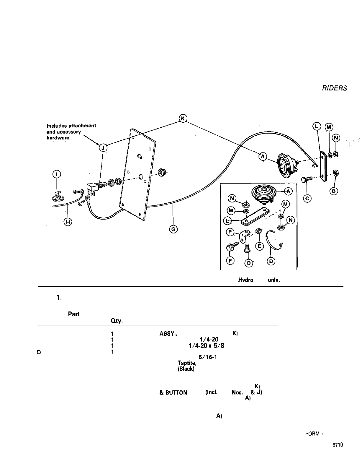
Figure
Ref.
NO.
A
8
C
D
E
F
G
H
I
J
K
L
M
N
0
P
1.
Pati
NO.
1679968
1930641
1921969
932747
1931277
1927477
1700095
1700094
1605761
1879959
1700643
my.
1
1
1
1
1
1
1
1
1
1
1
2
2
2
1
1
Mounting configuration
for Hvdro units onlv.
Description
HORN ASSY., (Included in Ref. No. K)
NUT, Flange Whizlock,
CAPSCREW, Hex.
TIE, Cable
NUT, Flange Whizlock,
CAPSCREW. Taptite, 5/16-18x 1.00
WIRE ASSY..
WIRE ASSY. (Red)
CONNECTOR, Wire, Self-Stripping
HORN BUTTON ASSY. (Included in Ref. No.
HORN &
MOUNTING PLATE (Included in Ref. No.
LOCKWASHER (Included in Ref. No. A)
NUT (Included in Ref. No. Al
SCREW (Included in Ref. No.
L-BRACKET (Included in Ref. No. A)
(Blackl
8UlTON
l/4-20
1/4-20x 5/8
5/16-l
8
ASSY. (Incl. Ref.
A)
,Nos.
A &
A)
1
K)
J)
FORM -
1702038
PRINTED IN U.S.A.
8710
Page 2
NOTE
Not all hardware supplied with horn kit will be used
for this installation. Discard excess hardware.
Refer to
figure 1 to familiarize yourself with the
assembly.
NOTE
On newer gear models, battery is not located in rear
compartment (see figure 3). This allows installation
by either of the following methods.
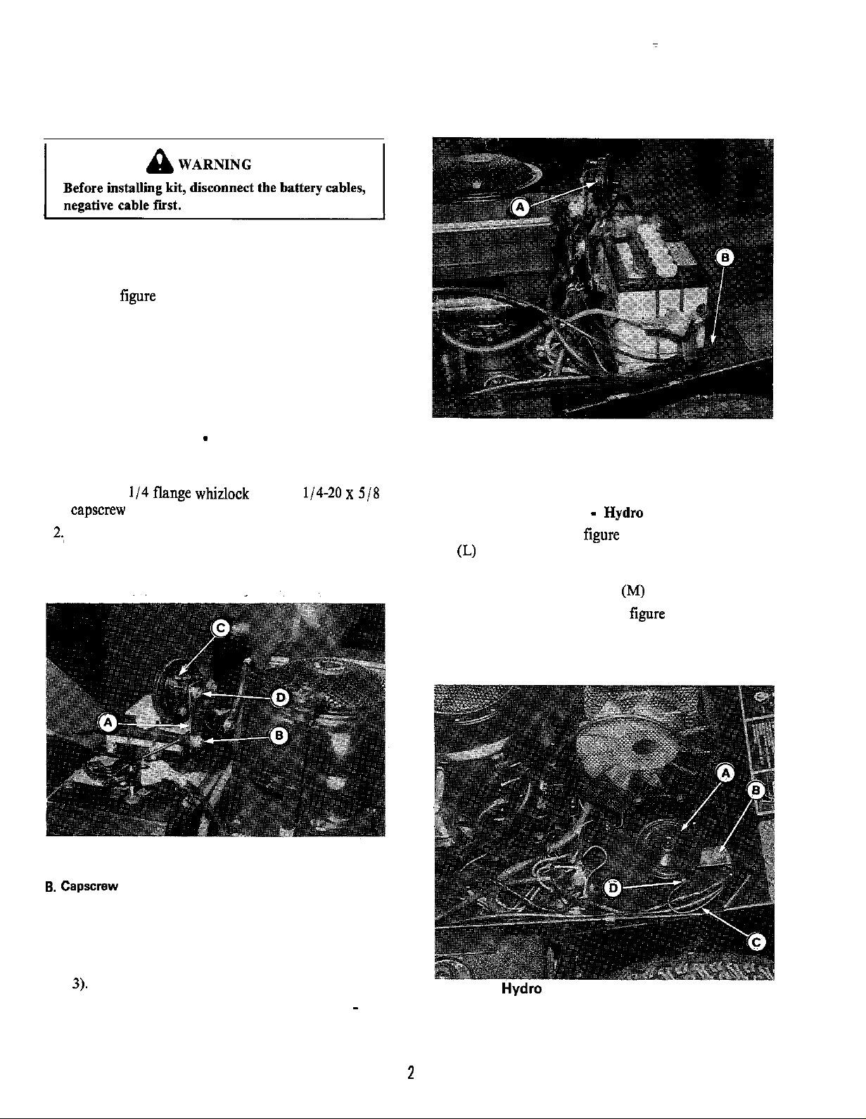
HORN INSTALLATION - Early Gear Models
1.
Install the two mounting plates (A, figure 2) together
and install onto the shift cable mounting bracket
using the
l/4
flange whizlock nut and l/4-20 x 5/8
capscrew (B).
2.,
Mount the horn by inserting it through the mounting,
plates (A) and installing lockwasher and nut (D).
Then, connect one end of the 45 inch black wire to,
either horn terminal (C).
Figure 3. Early Gear Models
A. Horn
B. Wire
HORN INSTALLATION - Hydra Models
1.
Connect the horn (A, figure 1) to the mounting plates
(L) with lockwasher (M) and nut (N).
2. Connect the L-bracket (P, figure 1) to the mounting
plates (L) with lockwasher (M) and nut (N).
3. Install the horn as shown in
figure 4 as follows.
a. Locate the existing screw and retainer under the
rear edge of footrest.
Figure 2.
A. Mounting Plates
6. capscrew
C. Terminal
D. Nut
3. Route the 45 inch wire along with other wires along
right-hand side of frame and under footrest (figure
3).
4. Go to HORN BUTTON INSTALLATION
Models.
-
All
Figure 4. Hydra ModelsFigure 4. Hydra Models
A. HornA. Horn
B. Mounting StrapsB. Mounting Straps
C. WireC. Wire
D. TerminalD. Terminal
2
Page 3

b. Remove this existing screw, and install new 5/ 16-
18
x 1 screw
(F),
being sure the retainer is in
original position.
c. Place the horn assembly into position onto the
screw and install the flange whizlock nut(E). The
horn should appear as in
,Connect the 45-inch wire(C) to either horn terminal
4.
CD).
Route the wire, under the footrest as shown.
figure 4.
5. Go to HORN BUTTON INSTALLATION
Models.
-
All
4. Route the 45-inch black wire (A, figure 6) up into
steerine column
thmuah
hole in frame.
HORN BUTTON INSTALLATION
1.
Remove the dash plate (A, figure 5) by removing six
-
All Models
screws (B). Disconnect plug from ignition switch.
2. Drill a
Il/
16 inch hole in the dash plate to install
horn button (C, figure 5) (shown installed). Measure
2 inches down from center of ignition switch. Then
measure
314
inch to left. Drill hole at that point.
3. Install the horn button in the hole by inserting the
button and securing with nut. Be sure terminals point
down before tightening nut.
Figure 6.
A. Wire
5. Connect the 45 inch black wire to either terminal of
the horn button.
6.
Connect the red wire supplied with kit onto the other
terminal of the horn button.
7. In this step, you will be connecting the red wire
installed in step 6 to an existing red wire that goes to
the ignition switch, using the self-stripping connector
supplied with kit.
a. Notice that in one terminal of the ignition switch
plug, there is a red and violet wire (this is the
terminal marked on switch). This is the red wire
you’ll be using.
b. Notice that the self-stripping connector has one
hole that does not go all the way through. Insert
red wire installed in step 6 into thii hole. Then,
place the
wnnector onto the red wire from
ignition switch and press closed with a pliers (red
wire will extend out both ends of connector.)
8. Install the plug onto ignition switch. Install the panel
’
with the six screws.
9. This completes the installation.
“L”
Figure 5.
A. Dash Plate
6. screws
C. Horn Button
D. Light Switch (Optional)
(6)
 Loading...