

Page 1
INSTALLATION
INSTRUCTIONS
WARNING
A
Stop the engine and remove key before
installing kit or making any adjustments.
NOTE: For tractor Mfg. No. 1691017 with serial number 1273 or lower, and tractor Mfg. No. 1601019 with
serial number 10400 and lower, it will be necessary to
replace the existing bracket support with part number
1676455 in order to install this kit.
NOTE: Make sure a// hydraulic wnnections are tight.
Where possible make connections using a vise before
installing parts on tractor.
FRONT IMPLEMENT Lb?- KIT
MFG. NO. 1691195
1.
Check kit parts against illustration and parts list on
pages 2 & 3.
2. Remove tractor hood to ease installation.
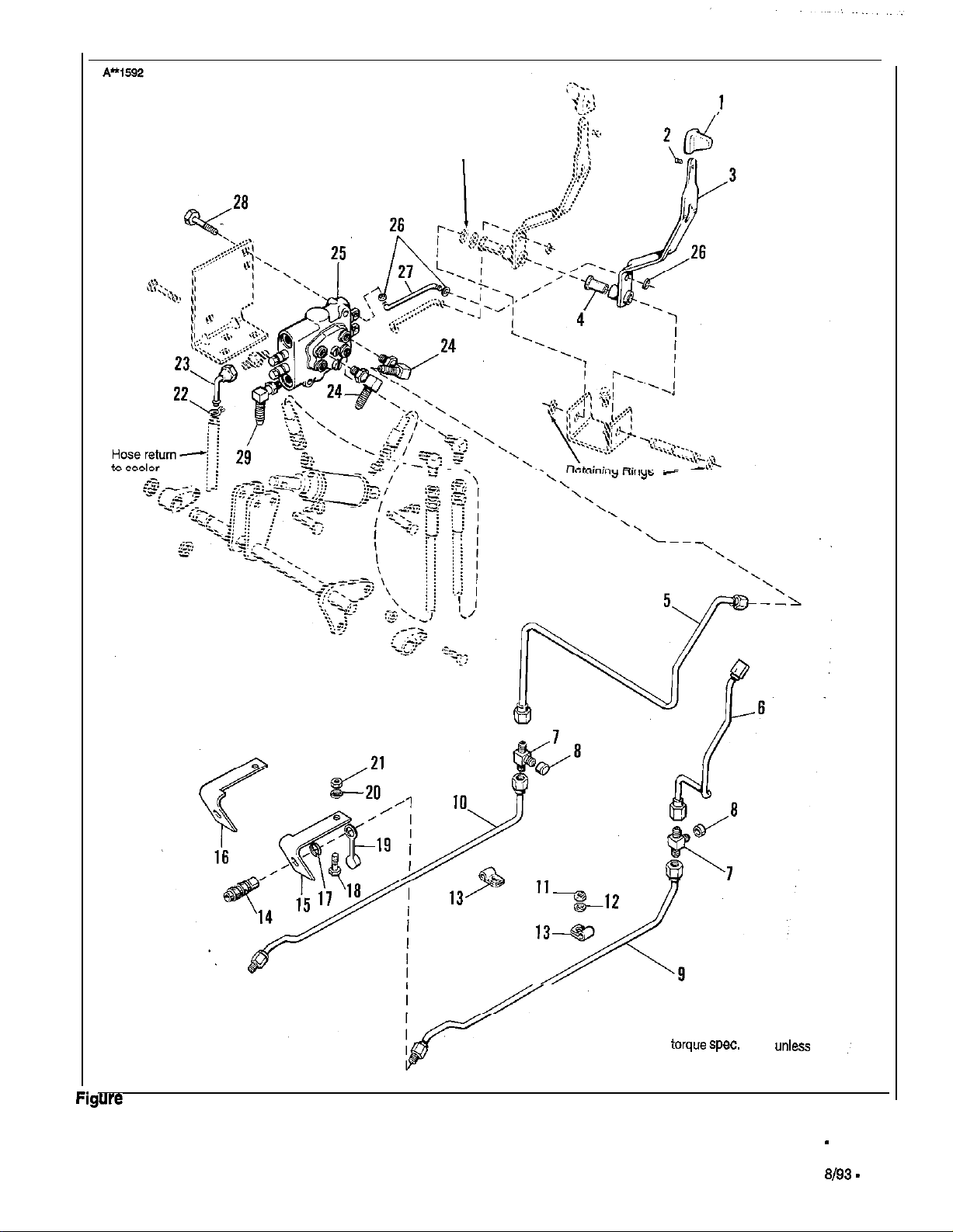
3.. See Figure 3. Remove the existing retaining rings.
Install the bushing (4) and lever (3). Install the curved
washers and retaining rings.
4. Disconnect hoses from existing valve. Note and mark
their positions. Remove the valve by removing nut
and bolt that holds the hydro fill tube.
5. Install the new valve using existing hardware and
new
i/4-20
x 2 capscrew (28, figure 3). This longer
capscrew also secures hydro fill tube clamp. Use the
upper hole in the mounting plate for the new cap-
screw as shown.
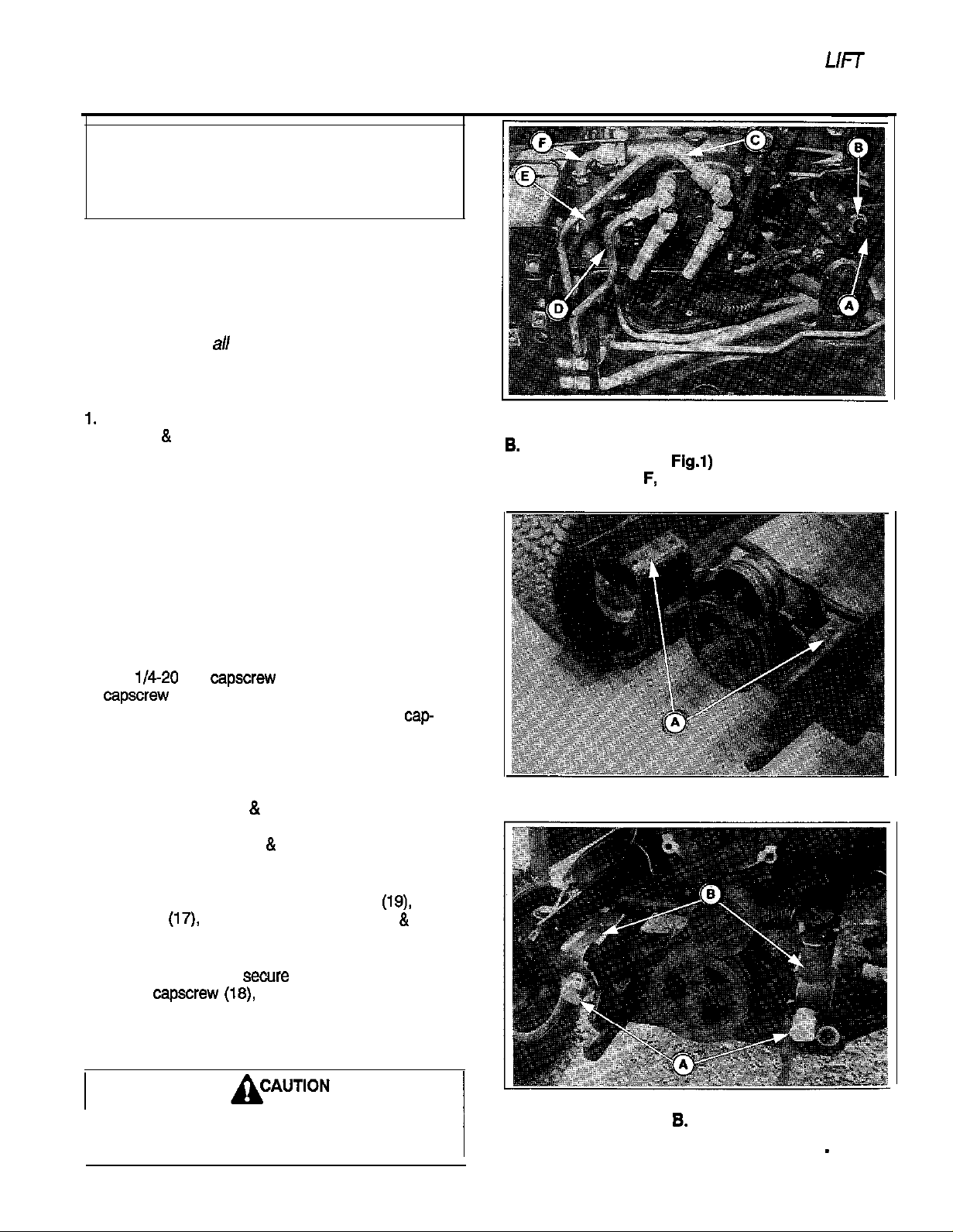
6. See figure 1. Connect the hoses to the new valve in
the same positions as on original valve. Connect the
right and left tubes (5
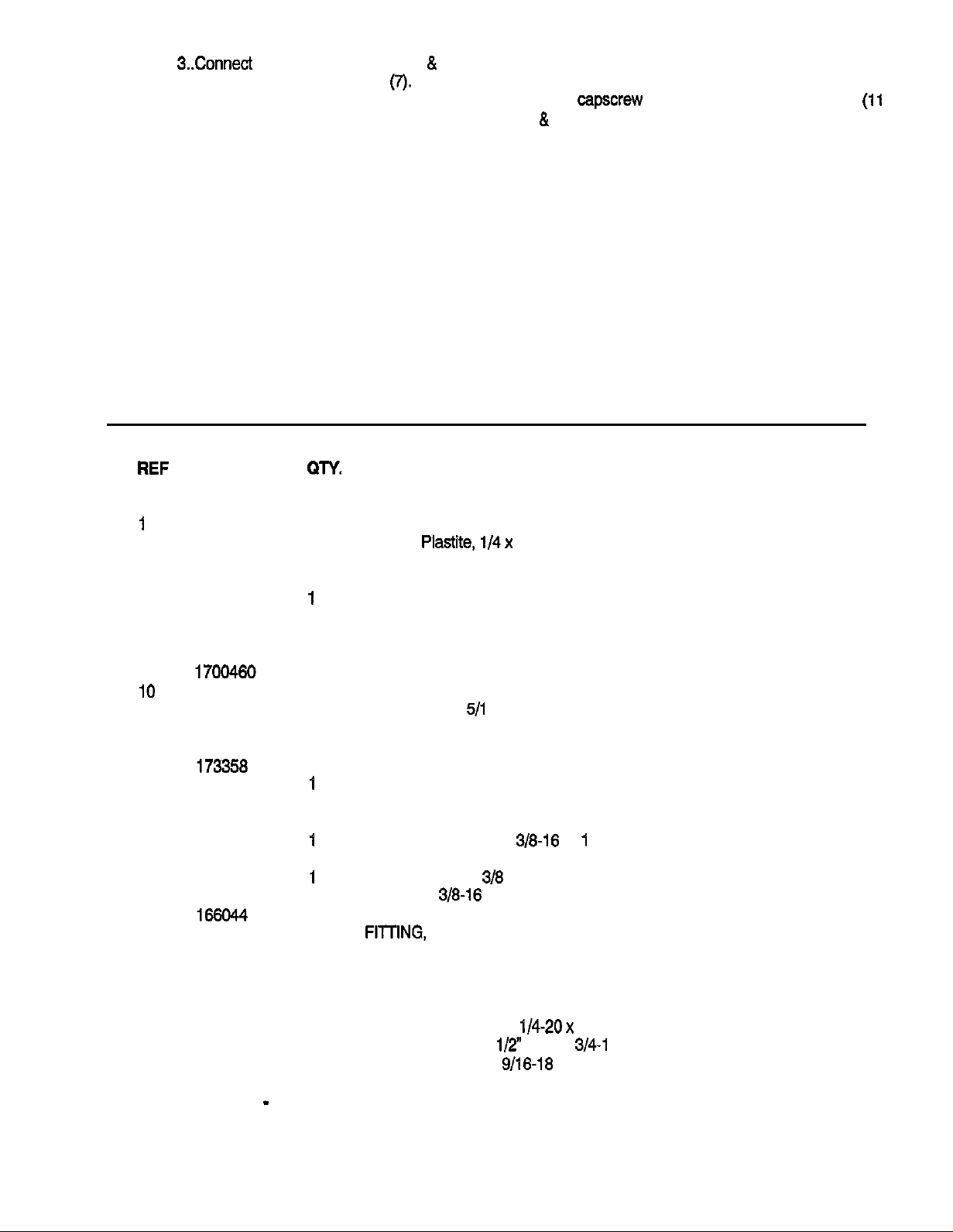
7, Route the front tubes (9 & 10, figure 3) under the
front brackets as shown in figure 2.
& 6, figure 3) as shown.
Figure 1.
A. Lift Lever Support E. Hose
8.
C. Tube, Right (Ref. E, Fig.1)
D. Tube, Left, (Ref. F, Fig. 1)
Figure 2. (Hood Removed)
A. Brackets
E-Ring F. Elbow
6. See figure 4. Assemble the plastic plugs
ing rings
Attach to tractor as shown in figure 3.
9.
On right-hand side, secure bracket (16, figure 3)
using capscrew
On left-hand side, secure bracket (15) using same
hardware used to secure bracket for PTO idler
spring.
The PTO spring is under tension when
Installed.
(17)
bodies (14) and brackets (15 & 16).
(16)
lockwasher (20) and nut (21).
(19)
retain-
Figure 3.
A. Plugs 8. Brackets
FORM - 1701802
Page 2
10. See figure
3Connect
the left and right tubes (5
&
6) to the front tubes (9, IO) using the tees (7).
11. Underneath tractor, notice that the front half of
frame is connected to rear half of frame. Locate the
front capscrews that connect the frame halves.
Secure the front tubes and clips (13, figure 3) to
each capscrew using the lockwashers and nuts
&
12, figure 3).
(11
FIEF
NO. NO.
1
2
3
4
5
6
7
6
9
10
11
12
13
14
15
16
17
16
19
20
21
22
23
24
* 26
26
27
26
29
PART
171165
1960106
1675968
175731
1676401
1676400
1700033
1700125
1674734
1922007
1909509
1677267
1677105
1677104
166017
1921210
173360
1916965
1916950
1701406
1675769
1708166
927769
1679063
1921963
921409
a-Y.
1
1
1
1
1
1
2
2
1
1
2
2
2
2
1
1
2
1
2
1
1
1
1
2
1
2
1
1
1
DESCRIPTION
KNOB, Control Handle
SCREW, Plastite,
1/4x
1
CONTROL LEVER ASSY.
BUSHING
TUBE ASSY., Right
TUBE ASSY., Left
UNION, Tee, 37
CAP
TUBE ASSY., Front, Left
TUBE ASSY., Front, Right
NUT, Hex Jam,
5/l
6-I 4
LOCKWASHER, Int. Tooth
CLIP, Tube
BODY ASSY., Female
BRACKET, Quick Disconnect, L.H.
BRACKET, Quick Disconnect, R.H.
RING, Retaining
CAPSCREW, Hex Hd.,
316-16 x
1
PLUG, Plastic
LOCKWASHER, 3/6
NUT, Hex, 3/8-16
CLAMP, Hose
FIlTlNG,
90 Swivel
FITTING, 90
VALVE ASSY., 2 Spool
RING, Retaining
LINK, Control
CAPSCREW, Hex Hd.,
FITTING, Hyd. Short
l/2”
1/4-20x
tube x
2
3/4-l
6 (For use with Early
Model Tractors wlth g/16-18 Valve Port)
*Standard Seal Repair Kit - Part No. 1679733
Form 1701802
Page 3
Curved
washer
.
\
‘\
‘\
‘\
-
‘l-
we
4. Front Implement Lift Kit
NOTE: Use standard hardware
torque spec.
otherwise noted.
3
chart
unless
FORM - 1701802
PRINTED IN U.S.A.
9193 -
,’
SMI
 Loading...