

Page 1
1
Installation
Instructions
Tube and Latch Kit
Part No. 1687262
Note: Use these Instructions to supplement portions of
the Operator’s Manual for Twin Catcher 1694916. Keep
these Instructions for future reference.
INSTALLATION
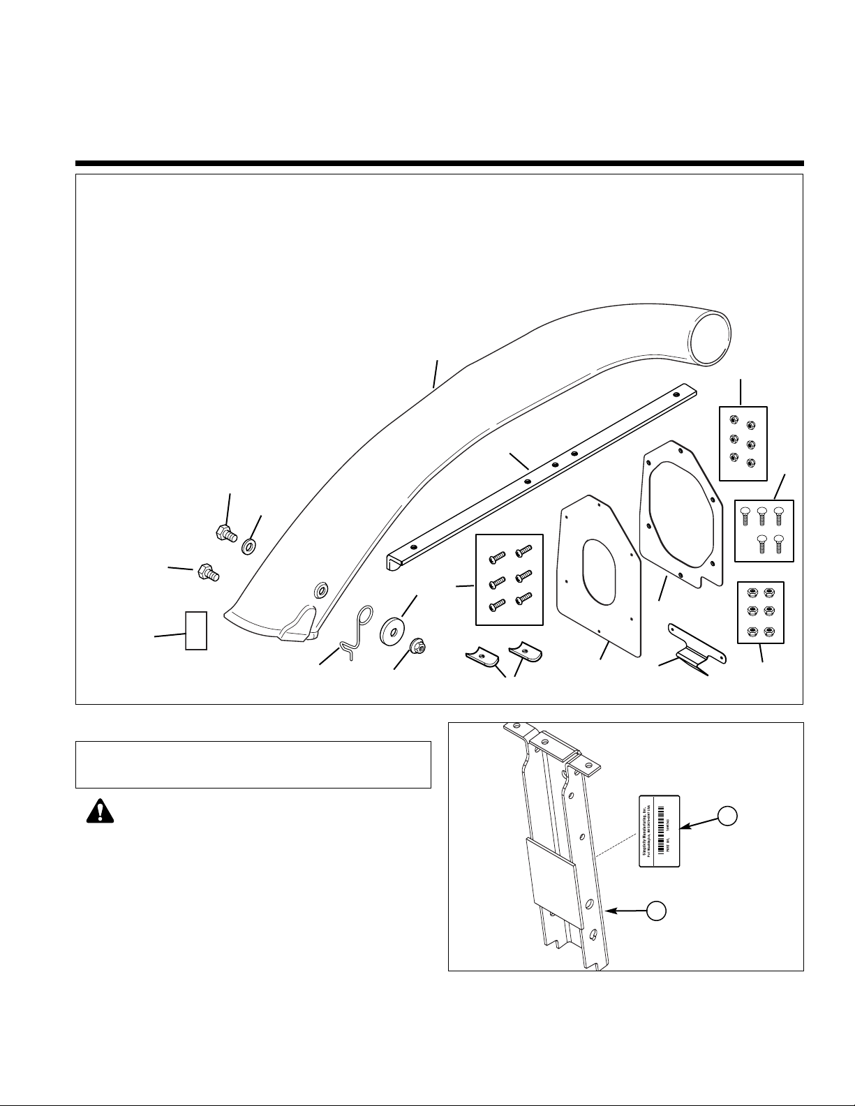
1. Apply new ID Label (A, Figure 2) directly over existing product ID Label on channel assembly (B).
For 38” Regent Series Twin Catchers
Figure 1. Contents
Figure 2. Apply New ID Label
A. ID Label, 1695163, (New)
B. Channel Assembly
Kit Contents:
Ref. Part No. Qty. Description
1 1732735A 1 Seal Plate
2 1732799 1 Seal
3 1960404 6 Screw, Phillips,
#10-24 x 3/4
4 1933896 6 Nut, Nylock,
#10-24
5 1703769 1 Tube
6 1704603 1 Latch, Tube
7 1960185 1 Washer, Flat
8 1935048 1 Nut, 5/16-18
9 1960122 1 Capscrew,
5/16-18 x 3/4
Ref. Part No. Qty. Description
10 1919326 1 Lockwasher,
5/16
11 1731420 1 Label, ID,
1695163
12 1931338 5 Carriage Bolts,
5/16-18 x 1-3/4
13 1720452 2 Saddle Clamp
Ref. Part No. Qty. Description
14 1960686 6 Nut, Nyloc,
5/16-18
15 1733432A 1 Brace
16 1930591 1 Capscrew,
5-16 x 3/4
17 1733416A 1 Latch
This kit is for updating a 1694916 Twin Catcher to
a 1695163 Twin Catcher.
A
4
Before beginning any service work turn off the
PTO, set the parking brake, turn off the ignition,
and disconnect the spark plug wire(s).
WARNING
1
17
2
8
5
3
7
6
9
10
B
11
12
15
14
13
16
Page 2
2
Installation Instructions Tube and Latch Kit
A
B
C
C
C
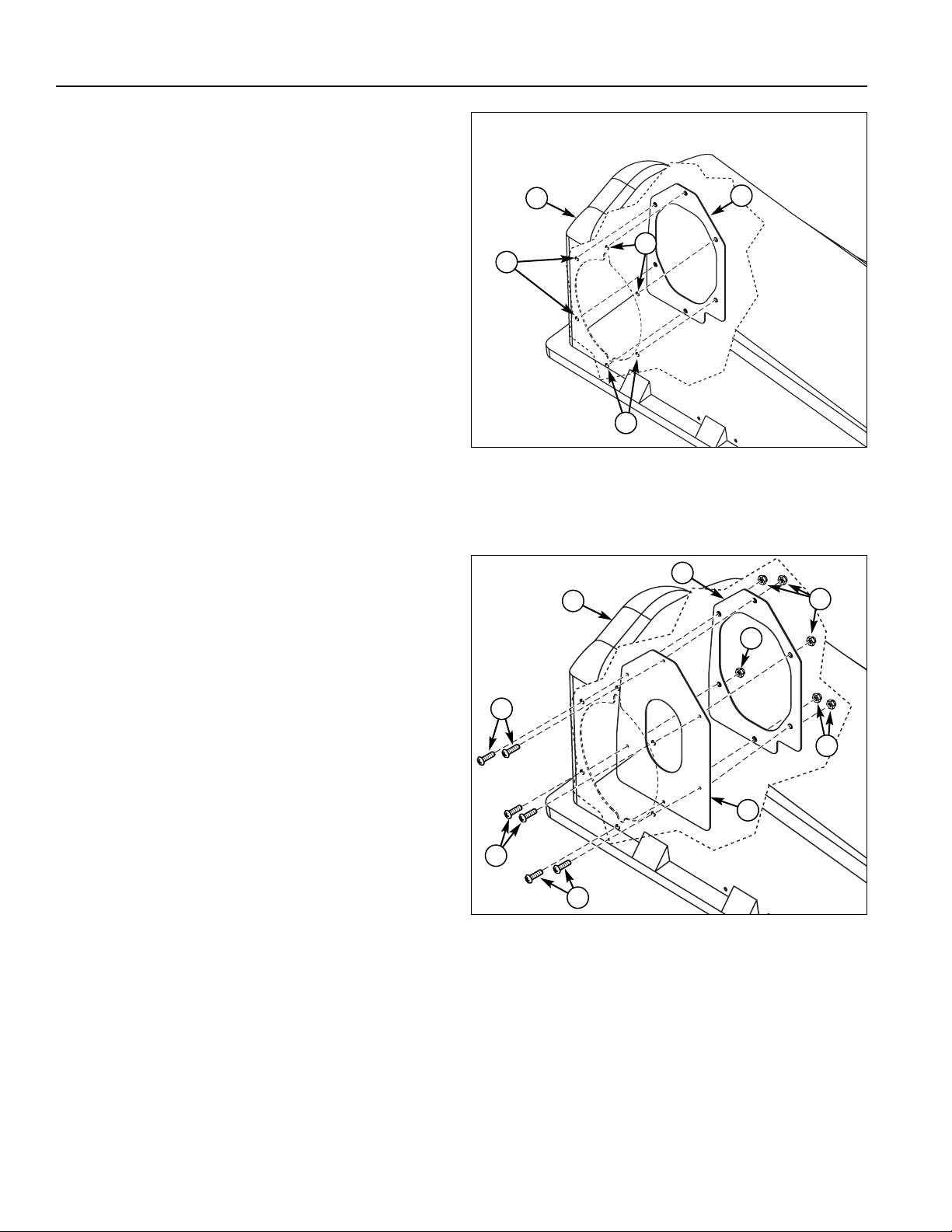
Figure 3. Drill Adapter Plate Holes
A. Cover Plate
B. Grass Catcher Cover
C. New13/64” Hole Locations
A
B
E
C
Figure 4. Install Seal and Cover Plate
A. Cover Plate
B. Grass Catcher Cover
C. Screw, Phillips, #10-24 x 3/4
D. Seal, Rubber
E. Locknuts, ESNA, #10-24
B
E
C
C
D
2. From the inside of grass catcher (B, Figure 3) cover
use cover plate (A) as a template to drill six 13/64”
holes (C) on grass catcher cover (B) as shown.
3. Inside grass catcher cover (B, Figure 4) place the
seal (D), and cover plate (A). Secure using #10-24 x
3/4 screws (C), and #10-24 locknuts (D).
Page 3

3
Tube and Latch Kit Installation Instructions
2“
Drill 11/32”
Hole Here
4. Drill a new 11/32 hole (A, Figure 5) 2” from the existing hole (B) in boot (C) as shown.
5. Secure the puck (B, Figure 6) to boot (A) using 5/1618 x 3/4 capscrew (C) and 5/16-18 locknut (D).
6. Remove and discard the latch (B, Figure 7) from the
cover assembly (A). Remove and retain #10-24 x 5/8
screws (D) and #10-24 locknuts (C).
7. Install the new latch (B, Figure 8) to the cover assembly (A) securing with Existing #10-24 x 5/8 screws (D)
and #10-24 locknuts (C) as shown.
A
B
Figure 5. Drill Hole In Boot
A. New 11/32” Hole
B. Existing Hole
C. Boot
C
Figure 6. Install Puck to Boot
A. Boot
B. Puck, Metal
C. Capscrew, Thin Head, 5/16-18 x 3/4
D. Locknuts 5/16-18
A
C
B
D
Figure 7. Remove Latch
A. Cover Assembly
B. Latch
C. Locknuts, Nylock, #10-24
D. Screws, #10-24 x 5/8
A
D
C
B
Figure 8. Install Latch
A. Cover Assembly
B. Latch (New)
C. Locknuts, ESNA, #10-24 (Existing)
D. Screws, #10-24 x 5/8 (Existing)
A
D
C
B
Page 4

4
Installation Instructions Tube and Latch Kit
8. Install the “U” tube (A, Figure 9) and “L” channel (F)
to channel assembly (B) securing with 5/16-18 x 3/4
carriage bolts (C) and 5/16-24 nuts (E).
9. Using the “L” channel as a guide drill two 11/32 holes
(G) in “U” tube (A) as shown. Install 5/16-18 x 1-3/4
carriage bolts (C) through new holes (G) and secure
with saddle clamps (F) and 5/16-18 locknuts (D) and
5/16-18 nuts (E).
10. Install 5/16-18 x 3/4 capscrew (H) and 5/16-18 locknut (D) as shown.
Connect Tube to Cover and Boot
1. Slide discharge tube (A, Figure 10) into seal (B). It
may be necessary to lengthen several slits (C) in
order for tube (A) to fit into seal (B)
2. Install boot according to Operator’s Manual.
A
D
C
D
C
C
F
D
F
D
Figure 9. Install “U” Tube
A. “U” Tube
B. Channel Assembly
C. Carriage Bolts, 5/16-18 X 1-3/4
D. Nuts, Nyloc, 5/16-18
E. “L” Channel
F. Saddle Brackets
G. New 11/32 Holes
H. Capscrew, 5/16-18 x 3/4
Figure 11. Install Discharge Tube to Boot
A. Boot
B. Discharge Tube
C. Metal Puck
D. Wire Form
Figure 10. Install Tube in Cover
A. Tube
B. Seal
C. Slits
A
B
C
H
E
B
G
G
A
D
C
B
Form No. 1733418-01
Rev. 5/2006
© 2006 Simplicity Manufacturing, Inc. All Rights Reserved
TP 200-4298-01-SK-SMA
MANUFACTURING, INC.
500 N Spring Street / PO Box 997
Port Washington, WI 53074-0997 USA
3. Attach the discharge tube (B, Figure 11) to boot (A)
and secure the tube by moving wire form (D) down
over metal puck (C).
4. Reverse connection to remove discharge tube.
 Loading...