

Page 1
1
Installation
Instructions
Clean-Out T ool Kit
Part No. 1687099
319 / 520 / 551 Single Stage, 5-13 HP
Intermediate or Large Frame Snowthrowers
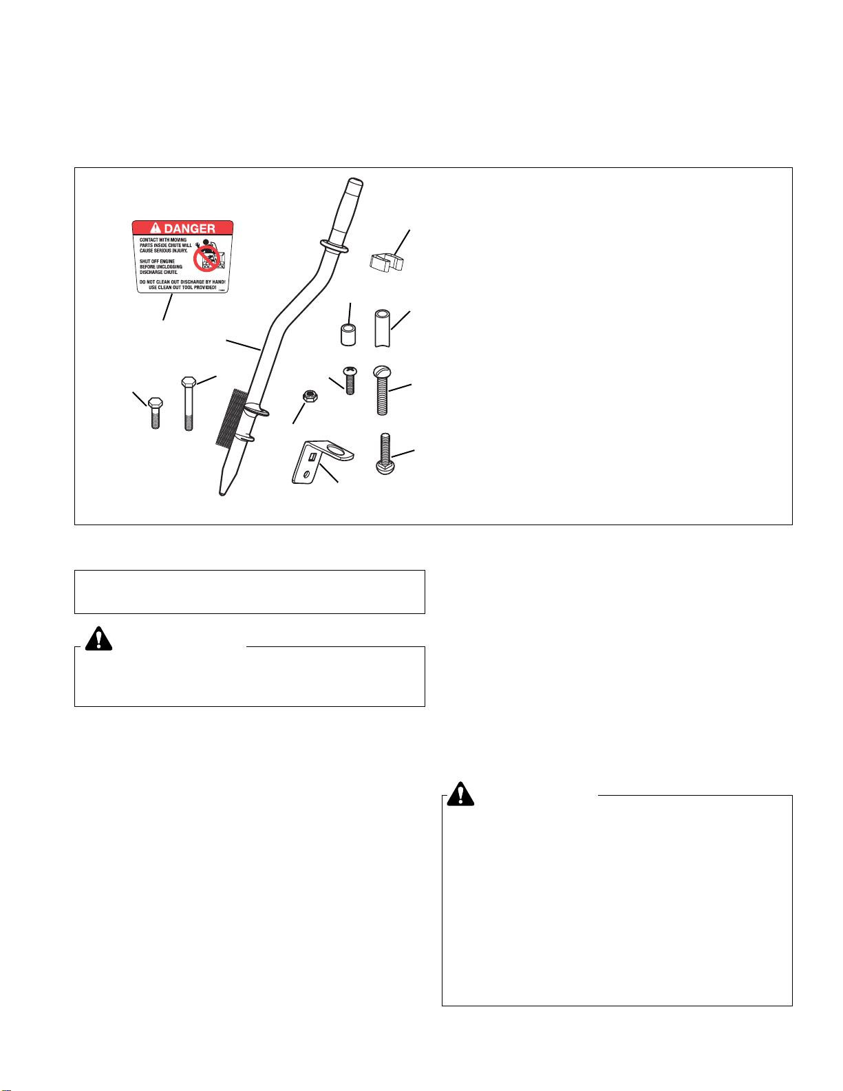
Figure 1. Contents
This kit is to install a clean-out tool on a variety of
snowthrowers.
Before beginning any service work turn off
ignition, and disconnect the spark plug wire.
WARNING
Kit Contents:
Ref. Part No. Qty. Description
1 1733209 1 CLEAN-OUT TOOL
2 1726727 1 BRACKET, Lower
3 1726728 1 CLIP
4 1726995 1 SPACER, 1-1/4” Long
5 1678392 1 SPACER, 11/32” Long
6 1960727 1 SCREW, Slotted, 10-24 x 2-1/2
7 1960589 1 SCREW, Phillips Head, 10-24 x 3/4
8 1933896 1 NUT, Nylock, 10-24
9 1960729 1 CAPSCREW, 5/16-18 x 1
10 1960730 1 CAPSCREW, 5/16-18 x 2
11 7071880 1 DECAL, Danger
12 1931338 1 Carriage Bolt, 5/16-18 x 1-3/4
5
11
3
1
2
4
10
9
8
6
7
DANGER
Do not clean out discharge chute with hands.
Contact with moving parts inside chute will
cause serious injury. Use clean out tool provided
with machine. Use the following procedure to
remove objects or clear the chute:
1. Stop the engine. Remove the key
2. Wait 10 seconds to be sure the auger/impeller
blades have stopped rotating.
3. Always use the clean-out tool. DO NOT use your
hands.
GENERAL OPERATION
After installation of the clean-out tool kit, make sure
clean-out tool is attached to handle on machine. Do not
operate the machine without the clean-out tool properly
stored on the handle.
Upon completion of installation of clean-out tool, keep
these instructions and warnings with the Operator’s
Manual.
Note: For proper use of clean-out tool it may be necessary on some models to remove the wire guard from the
chute.
12
CLEARING A CLOGGED DISCHARGE
CHUTE
Hand contact with the rotating impeller inside the discharge chute is the most common cause of injury associated with snowthrowers. Never use your hand to clean
out the discharge chute.
To clear the chute:
1. SHUT OFF THE ENGINE.
2. Wait 10 seconds to be sure the impeller blades have
stopped rotating.
3. Always use a clean out tool, not your hands.
Page 2
2
Installation Instructions Clean-Out T ool Kit
INSTALLATION
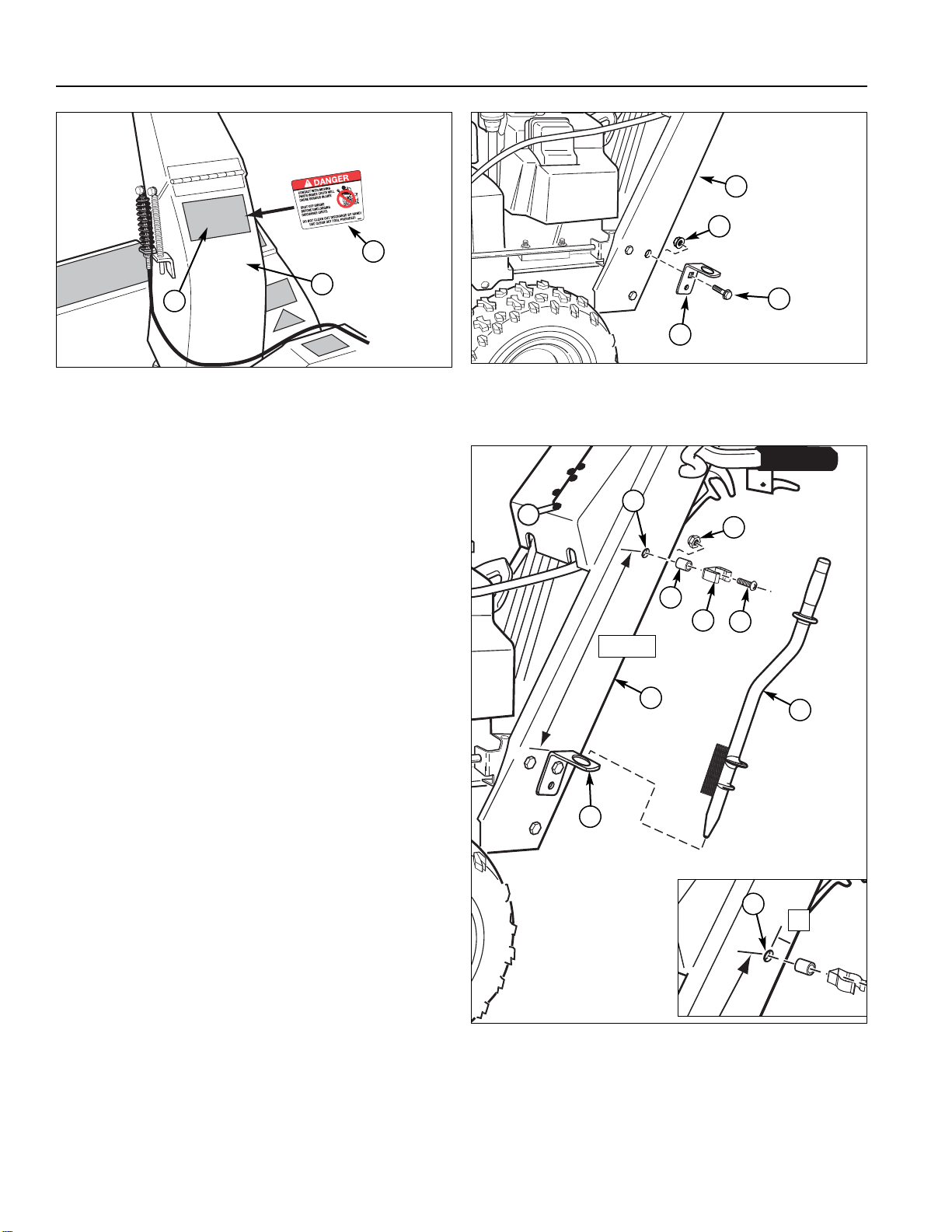
Decal Installation
1. Clean and dry existing danger decal (A, Figure 2) and
surrounding area.
2. Apply new decal (C) by removing the backing from
decal and placing directly over existing decal (A)
aligning top edges of both decals.
Clean-Out T ool Installation
(CHANNEL HANDLE MODELS)
1. Remove existing hardware (A, Figure 3) from upper
back hole on left side handle (C) as shown.
2. Using square hole install lower bracket (B) into upper
back hole on left side handle (C) as shown. Secure
with existing hardware (A).
3. Measure 16-3/8” from top of bracket (A, Figure 4) to
center of handle (B). Center punch and drill a new
13/64 hole (B) in handle.
Note: If using a cab with snowthrower locate hole (B) 1”
from edge. See inset in Figure 4.
4. Attach clip (D) to handle (H) securing with #10-24 x
3/4 screw, 11/32 spacer (C), and #10-24 nut (F)
mounting through new hole (B).
5. Attach clean out tool (G) to handle (H) by first placing
pointed end into bracket (A), then pushing hand grip
into clip (D).
6. Read and follow warnings when using the clean-out
tool.
Figure 2.
A. Existing Danger Decal C. New Danger Decal
B. Discharge Chute
A
C
B
Figure 3. Mounting Lower Bracket (Channel Handle)
A. Existing Hardware C. Handle, LH
B. Lower Bracket
16-3/8”
A
C
B
A
C
B
A
Figure 4. Mounting Clean-Out Tool (Channel Handle)
A. Bracket F. Locknut, #10-24
B. New Hole, 13/64” G. Clean-Out Tool
C. Spacer, 11/32, H. Handle, LH
D. Clip
E. Screw, Phillips, #10-24 x 3/4
D
E
G
F
1”
B
H
Page 3

3
Clean-Out T ool Kit Installation Instructions
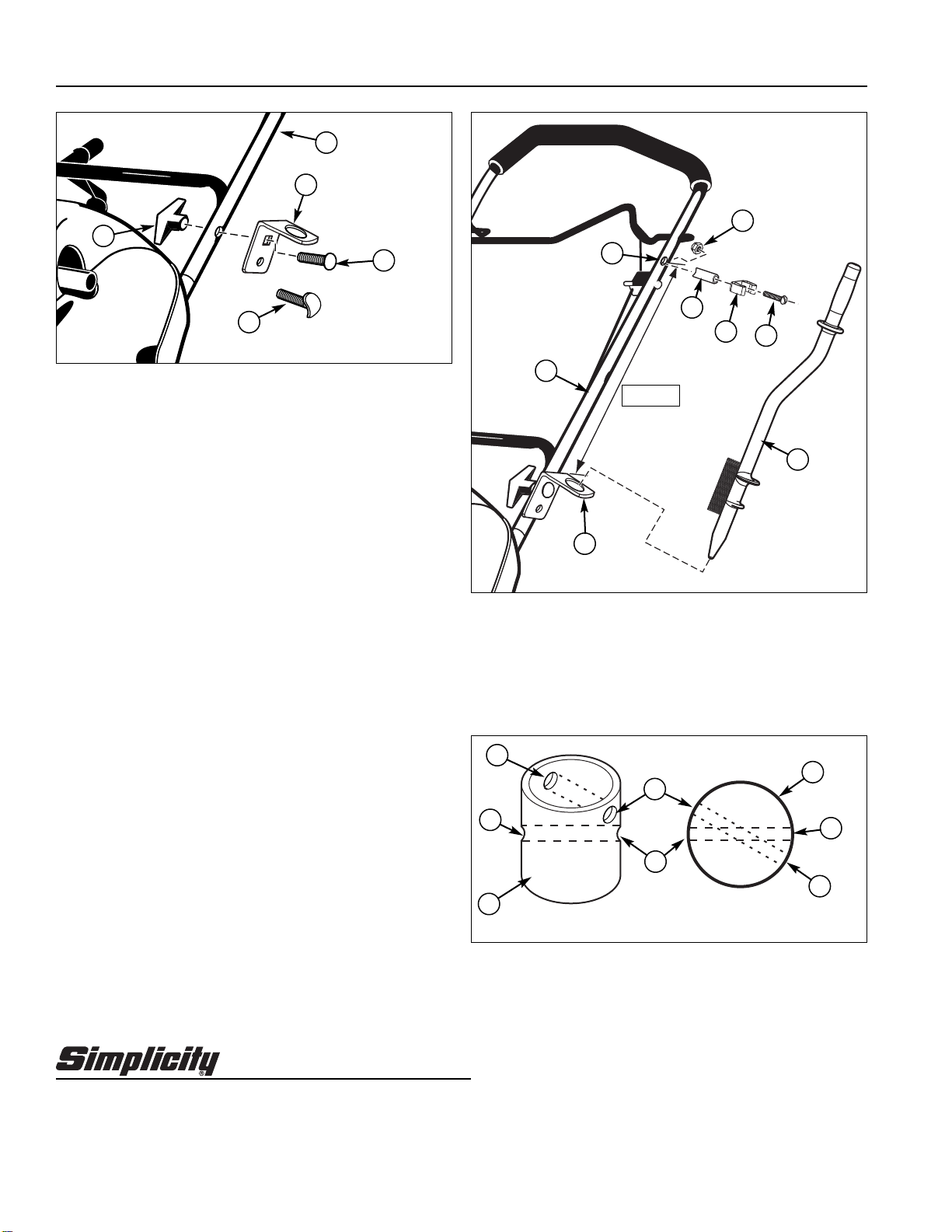
(TUBE HANDLE MODELS)
1. Remove existing hardware (A, Figure 5) from upper
hole on left side handle (C) as shown. Discard capscrew (D).
2. Using square hole install lower bracket (B) into upper
hole on left side handle (C) as shown. Secure with
new 5/16-18 x 2 capscrew (D) and nut (A).
Note: In some cases the upper hole in the left side handle is crimped flat. If so use 5/16-18 x 1 capscrew (D).
3. Measure 16-3/8” from top of bracket (A, Figure 6) to
center of handle (B). Center punch and drill a new
13/64 hole (B) in handle (H).
4. Attach clip (D) to handle (H) securing with #10-24 x
2-1/2 screw (E), 1-1/4” spacer (C), and #10-24 locknut (F) mounting through new hole (B).
5. Attach clean out tool (G) to handle (H) by first placing
pointed end into bracket (A), then pushing hand grip
into clip (D).
6. Read and follow warnings when using the clean-out
tool.
Figure 5. Mounting Lower Bracket (Tube Handle)
A. Existing Hardware C. Handle, LH
B. Lower Bracket D. Capscrew
A
C
B
D
A
16-3/8”
A
C
B
D
E
F
H
Figure 6. Mounting Clean-Out Tool (Tube Handle)
A. Bracket F. Locknut, #10-24
B. New Hole, 13/64” G. Clean-Out Tool
C. Spacer, 1-1/4” H. Handle, LH
D. Clip
E. Screw, Slotted, #10-24 x 2-1/2
G
Page 4
4
Installation Instructions Clean-Out T ool Kit
(520 MODELS)
1. Remove wing lock knob (A, Figure 7) and carriage
bolt (E) or screw (C) from hole on left side handle (D)
as shown. Discard screw (C) if it was used originally.
2. Using square hole install lower bracket (B) into hole
on left side handle (D) as shown. Secure with existing
or new 5/16-18 x 1-3/4 carriage bolt (E) and wing lock
knob.
3. Measure 15-3/8” from top of bracket (A, Figure 8) to
center of handle (B). Center punch and drill a new
13/64 hole (B) in handle (H).
4. Attach clip (D) to handle (H) securing with #10-24 x
2-1/2 screw, 1-1/4” spacer (C), and #10-24 locknut
(F) mounting through new hole (B).
5. Attach clean out tool (G) to handle (H) by first placing
pointed end into bracket (A), then pushing hand grip
into clip (D).
6. Read and follow warnings when using the clean-out
tool.
(319 MODELS)
Mount to right hand side handle of unit following the
same instructions for the 520 models. Rotate position of
new clean-out hole (B, Figure 9) approximately 30
degrees from existing bail hole (C) to avoid interference
of bail operation.
Figure 7. Mounting Lower Bracket (520)
A. Wing Lock Knob D. Handle, LH
B. Lower Bracket E. Carriage Bolt,
C. Screw, Curved Head 5/16-18 x 1-3/4
B
A
E
C
15-3/8”
A
C
B
D
E
F
H
Figure 8. Mounting Clean-Out Tool (520)
A. Bracket F. Locknut, #10-24
B. New Hole, 13/64” G. Clean-Out Tool
C. Spacer, 1-1/4” H. Handle, LH
D. Clip
E. Screw, Slotted, #10-24 x 2-1/2
G
D
Figure 9. Hole Location 319 Models
A. Handle C. Existing Bail Hole
B. New Clean-Out Tool Hole
A
C
B
Top View
A
C
B
B
C
Cross Section View
MANUFACTURING, INC.
500 N Spring Street / PO Box 997
Port Washington, WI 53074-0997 USA
Form No. 1727771-02
Rev. 01/2007
TP 200-4147-02-SK-SN
Briggs & Stratton Yard Power Products Group
Copyright © 2007 Briggs & Stratton Corporation
Milwaukee, WI USA. All Rights Reserved
 Loading...