

Page 1
INSTALLATION
GENERAL
The Spring Assist Kit is used to retrofit the hitch used to
install the 42” and 46” Snow Plow/Dozer Blade on
several different models (series) of tractors. For easier
understanding of this instruction sheet, first identify the
size of blade (42”
you are working. Follow these specifications throughout
the ten steps.
Tractors:
Group 1:
Group 2: 800,600O
Group 3: 700,700O
Group 4: 900, 7100
Snow Plow/Dozer Blade:
42”
Mfg. No. 1690085 (Group 1, 2 tractors)
42”
Mfg. No. 1691520 (Group 3, 4 tractors)
46”
Mfg. No. 1~690088 (Group 3, 4 tractors)
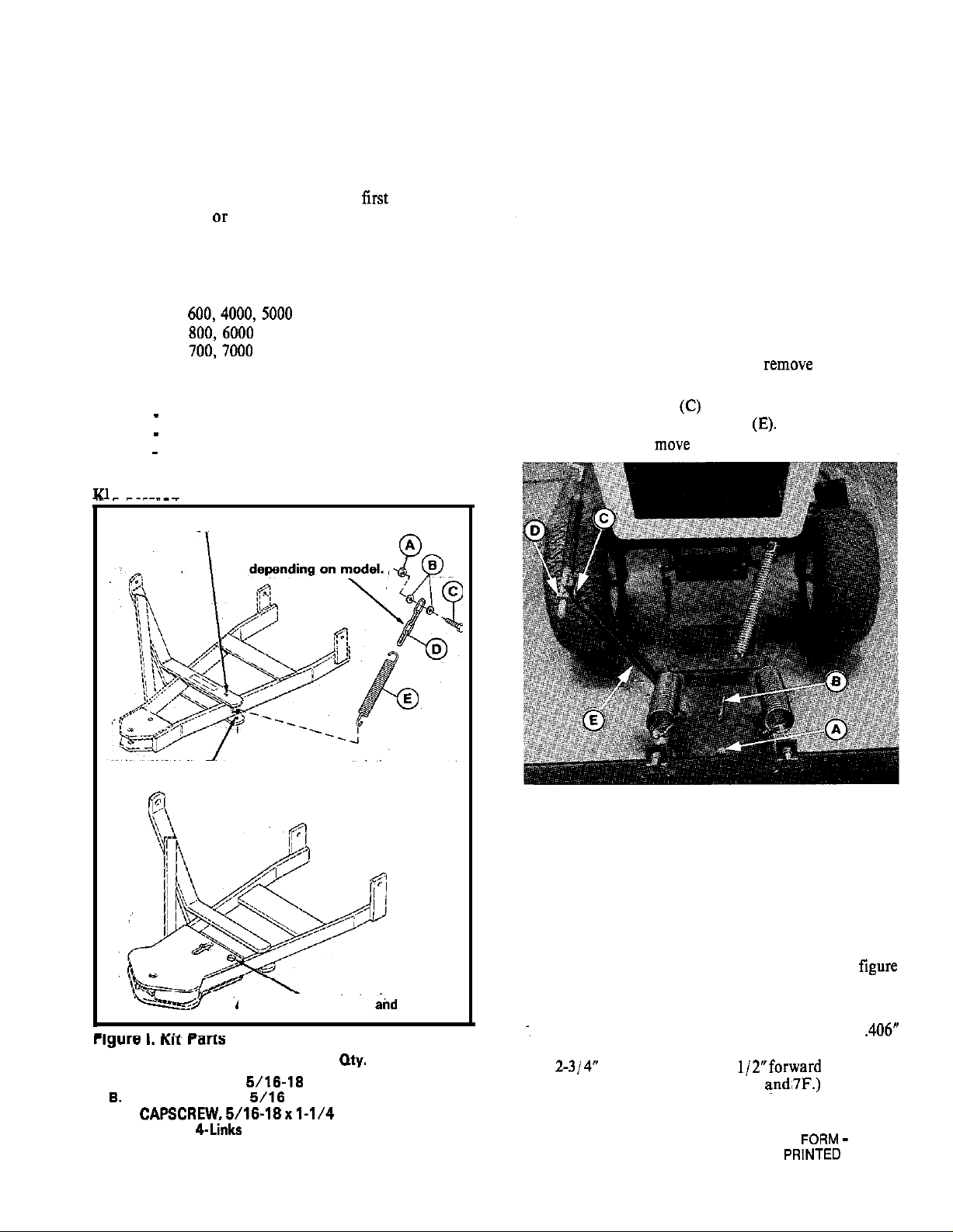
IT PARTS
Mounting location for 42” blade on Group 2 tractors
Use 0, 1, 2 or 4 links
INSTRUCTIONS
SPRING ASSIST KIT
MFG. NO. 1685336
INSTALLATION
1. Park tractor on a flat, level surface. Shut off engine,
remove key and apply parking brake.
2. Release lift handle so that dozer blade rests on the
ground.
3. Remove spring clip from king pin (A, figure 2).
Remove king pin and pivot pin (B) from push bar.
Slide dozer blade forward and
bar.
4. Remove cotter pin (C) from rod guide(D). Remove
rod guide from hitch bracket
now be free to move up and down.
from push
Push bar should
Mounting location for 42” Group 1, 3 and
Mounting location for
46” blade on Group 3
Ref. Description
A. NUT, Hex Lock,
WASHER, Plain,
C.
D. CHAIN, 4-Links
E.
SPRING
Part Number
1
2 1919381
1
1
1
4 tractors
4 tractors
1923362
1921977
1669241
1675232
Figure 2. Dozer Blade Removal
A. King Pin
B. Pivot
C. Cotter Pin
D. Rod Guide
E. Hitch Bracket
5. Drill a hole in the bottom cross member (42” blade
on Group 1, 3 and 4 Series tractors) or
upper cross member (42” blade on Group 2 tractors)
according to the diagrams of the templates in
3. Actual templates are on a separate insert included
with these instructions.
For 46” blades on Group 3 and 4 tractors, drill a
hole in the (top) front plate. Hole should be located
rear edge. (Refer to figures 7E
1
1701916
IN U.S.A.
878
Page 2
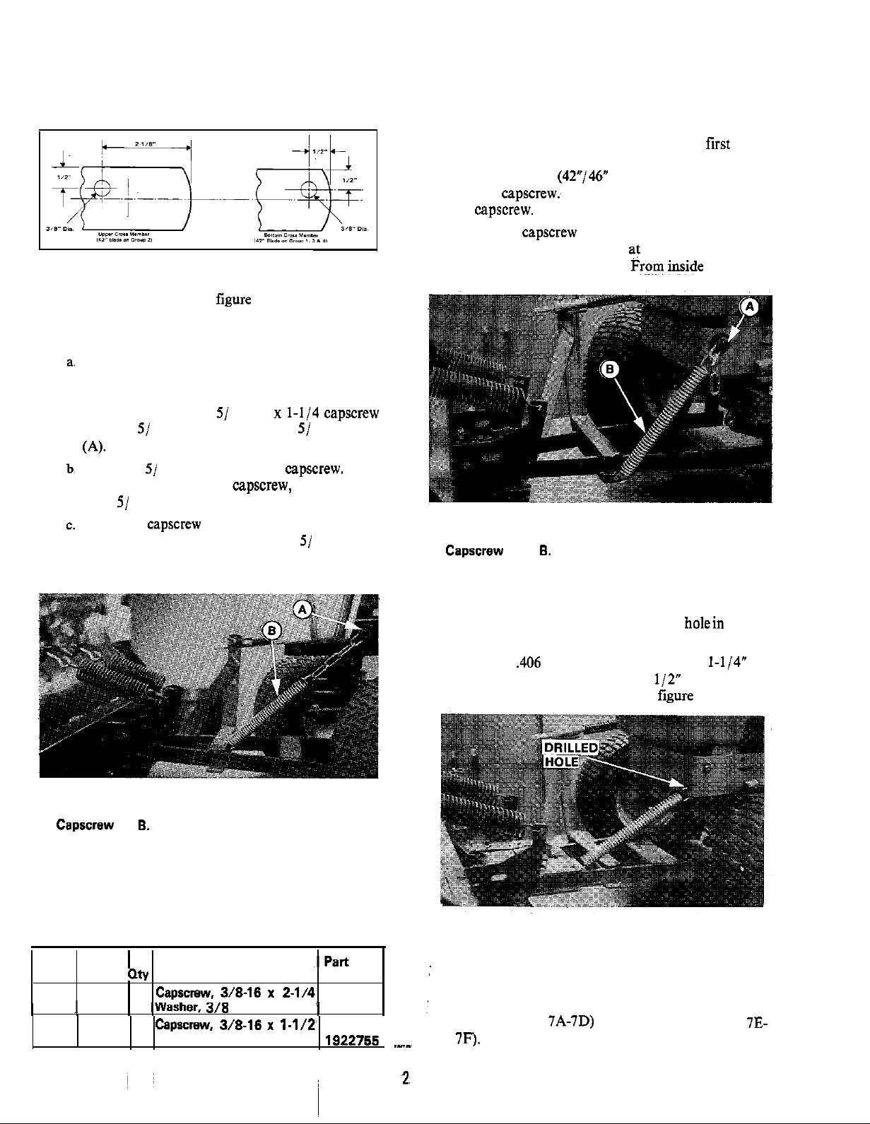
Figure 3. Diagrams of Hitch Templates
6. Assemble the chain (D,
follows:
42”
Blade on Group 1 and 2
On left-hand side, remove and discard the upper
self-tapping screws that holds bumper to frame.
This is the hole used for installing chain in the
following steps, using 5/ 16-18 x
(C), two
capscrew
c.
Place one washer onto capscrew. Place first link of
chain (42” blade on Group 3 tractor) or second
link of chain
on
Install final two washers on
d. Insert capscrew (A, figure 5) through tractor
frame. Tighten snug only
will be installed in step 7.) From inside the frame,’
install locknut.
Place one 5/ 16 washer onto the
Then
place the chain on the capscrew, and then the
other 5/ 16 washer:
Insert the capscrew (A, figure 4) through tractor
frame. From inside the frame, install
onto capscrew. Tighten snug only at this time.
(Spring (B) will be installed in step 7.)
Figure 4. Chain Installation (Group 2 Tractor
Shown)
A.
Spring
42” Blade on Group 3 and 4; 46” Blade on Group 4
a.
On the left hand side, remove the front hood pivot
bolt.
b. Chain must be installed with the following
hardware (not included in this kit):
Figure 5. Chain Installation (Group 3 Tractor
Shown)
A.
Spring
46” Blade on Group 3
a. The chain is not used to secure spring to tractor
frame. Spring is installed directly to
tractor
frame.
b. Drill a
from the front left side and
hole in the front of frame l-114” in
up from the
bottom of the frame. Refer to
Figure 6. Spring Installation (Group 4 Tractor
Shown)
Blade Tractor Qty Hardware
42” Group 3 1
,
3
42” Group 4
46”
1
3 Washer
3/6
Number
2-l/4’ 1922130
1622766
1921969
7. Raise the push bar and hook up one end of spring to
chain or frame as shown in figures 7A through 7F.
Hook other end of spring to hole drilled in hitch cross
member (figure
Page 3

Figure 7A. 42” Blade
Group
From Top Down
1
Figure 7D. 42” Blade
Group 4
Figure 76. 42” Blade
Figure 7C. 42” Blade
Group 2
Group 3
Figures 7A
8.
Lower push bar and install dozer blade with kingpin
(A,
spring clip, and pivot pin(B). Reattach
rod guide (D) and secure with cotter pin (C).
9. Tighten capscrew (A, figure 4 or 5) and nut which
hold chain to tractor frame.
Perform Lift Rod Adjustment as instructed in
Operator’s Manual for your Snow Plow/Dozer
Blade.
Figure 7E. 46” Blade
Figure 7F. 46” glade
7F. Spring Installation
Group 3
Group 4
Page 4

Upper Cross Member
(42” blade
Group 2)
Dia.
Bottom Cross Member
4)
Actual Templates of Figure 3.
INSERT
1701016
 Loading...