

Page 1
OPERATING INSTRUCTIONS
Not for
Reproduction
1695924 CHIPPER/SHREDDER
Model 1695924
Briggs and Stratton
305cc
1713249
Revision K
Page 2

Not for
Reproduction
Page 3

OPERATOR INSTRUCTIONS AND PARTS
Not for
Reproduction
1695924 Chipper/Shredder
Table of Contents
Safety Rules & Information .........................................................................................................................4
Safety Decals ...........................................................................................................................................................8
Safety Icons .............................................................................................................................................................8
Identification Numbers ...........................................................................................................................................10
Initial Assembly ......................................................................................................................................... 11
Initial Assembly ...................................................................................................................................................... 11
Features & Controls .................................................................................................................................. 14
Control Functions ...................................................................................................................................................14
Operation ....................................................................................................................................................15
General Operating Safety ......................................................................................................................................15
Adding Fuel ............................................................................................................................................................15
Starting the Engine ................................................................................................................................................15
Stopping the Engine ............................................................................................................................................... 16
Processing Materials .............................................................................................................................................. 16
Chipping / Shredding Recommendations ..............................................................................................................17
Storage...................................................................................................................................................................17
Regular Maintenance ................................................................................................................................18
Maintenance Schedule & Procedures .................................................................................................................... 18
Check for Loose Hardware..................................................................................................................................... 18
Check Safety Labels .............................................................................................................................................. 18
Inspect Cone, Hopper, & Guards ...........................................................................................................................18
Clean Debris from Engine & Chipper .....................................................................................................................19
Inspect / Rotate Shredding Hammers ....................................................................................................................19
Inspect Chipping Knives .........................................................................................................................................20
Check / Change Engine Air Cleaner ...................................................................................................................... 20
Replace Spark Plug ...............................................................................................................................................20
Engine Oil Type and Capacity ................................................................................................................................ 21
Check Engine Oil Level .......................................................................................................................................... 21
Change Engine Oil .................................................................................................................................................21
Troubleshooting & Repair ......................................................................................................................... 22
Troubleshooting Chart ............................................................................................................................................ 22
Repair ....................................................................................................................................................................23
Specifications ............................................................................................................................................ 25
Warranty ................................................................................................................................................
26-27
NOTE: In this manual, “left” and “right” are referred to as seen from the operating position.
Page 3
Page 4
OPERATOR INSTRUCTIONS AND PARTS
Not for
Reproduction
1695924 Chipper/Shredder
Safety Rules & Information
Operating Safety
Congratulations on purchasing a superior-quality piece
of lawn and garden equipment. Our products are
designed and manufactured to meet or exceed all industry
standards for safety.
Power equipment is only as safe as the operator. If it is
misused, or not properly maintained, it can be dangerous!
Remember, you are responsible for your safety and that of
those around you.
Use common sense, and think through what you are
doing. If you are not sure that the task you are about to
perform can be safely done with the equipment you have
chosen, ask a professional: contact your local authorized
dealer.
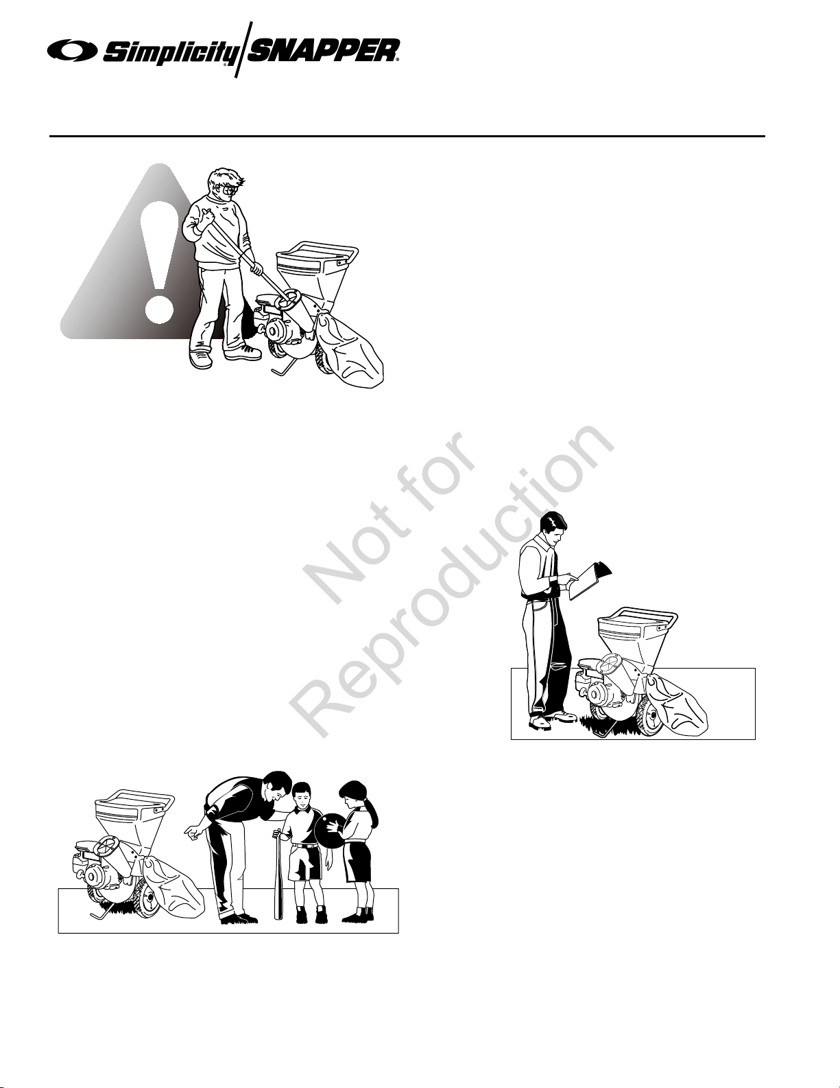
Read the Manual
The operator’s manual contains important safety information you need to be
aware of BEFORE you operate your unit as well as DURING operation.
Safe operating techniques, an explanation of the product’s features and
controls, and maintenance information is included to help you get the
most out of your equipment investment.
Be sure to completely read the Safety Rules and Information found
on the following pages. Also completely read the Operation section.
Tragic accidents can occur with children. Do not allow
them anywhere near the area of operation. Children
are often attracted to the unit and usage activity. Never
assume that children will remain where you last saw
them. If there is a risk that children may enter the area
where you are operating, have another responsible adult
watch them.
Children
Page 4
Page 5

Moving Parts
Not for
Reproduction
This equipment has many moving parts that can injure you or
someone else. However, if you follow all the rules in this book,
the unit is safe to operate.
The chipper/shredder has spinning blades that can amputate
hands and feet. Do not allow anyone near the equipment
while it is running! Do not place hands or feet in the hopper or
chipper cone, or discharge chute.
OPERATOR INSTRUCTIONS AND PARTS
1695924 Chipper/Shredder
Safety Rules and Information
Thrown Objects
This unit discharges debris at high speeds. Always wear protective goggles
and do not operate without the debris bag in place. Also, do not allow anyone
in the area while the unit is running! If someone does enter the area, shut the
unit off immediately until they leave. Organize the work area prior to starting
work.
Fuel and Maintenance
Gasoline is extremely flammable. Its vapors are also extremely flammable
and can travel to distant ignition sources. Gasoline must only be used as a
fuel, not as a solvent or cleaner. It should never be stored any place where
its vapors can build up or travel to an ignition source like a pilot light. Fuel
belongs in an approved, plastic, sealed gas can, or in the fuel tank with the
cap securely closed. Spilled fuel needs to be cleaned up immediately.
Proper maintenance is critical to the safety and performance of your unit.
Be sure to perform the maintenance procedures listed in this manual,
especially periodically testing the safety system.
Page 5
Page 6

OPERATOR INSTRUCTIONS AND PARTS
Not for
Reproduction
1695924 Chipper/Shredder
Safety Rules & Information
Read these safety rules and follow them closely. Failure to obey these rules could result in loss of control
of unit, severe personal injury or death to you, or bystanders, or damage to property or equipment.
This unit is capable of amputating hands and feet and throwing objects. The triangle in text
signifies important cautions or warnings which must be followed.
PREPARATION
1. Do not operate the equipment without wearing
adequate outer garments and safety goggles. Avoid
loose-fitting clothes and use protective footwear that
will improve footing on slippery surfaces.
TRAINING
1. Read the operating and service instructions carefully.
Be thoroughly familiar with the controls and the
proper use of the equipment. Know how to stop the
unit and disengage the control quickly.
2. Keep the area of operation clear of all persons,
particularly small children, and pets.
GENERAL OPERATION
1. Read, understand, and follow all instructions in the
manual and on the unit before starting.
2. Do not put hands or feet near rotating parts or under
the machine. Keep clear of the discharge opening at
all times.
3. Only allow responsible adults, who are familiar with
the instructions, to operate the unit (local regulations
can restrict operator age).
4. Be sure the area is clear of other people before
operating. Stop the unit if anyone enters the area.
5. Never direct discharge material toward anyone. Avoid
discharging material against a wall or obstruction.
Material may ricochet back toward the operator.
6. Operate the machine only in daylight or good artificial
light.
7. Do not operate the unit while under the influence of
alcohol or drugs.
8. Always wear eye and hearing protection when
operating this unit.
9. Keep in mind the operator is responsible for accidents
occurring to other people or property.
10. It is a violation of California Public Resource Code
Section 4442 to use or operate the engine on or near
any forest-covered, brush-covered, or grass-covered
land unless the exhaust system is equipped with a
spark arrester meeting any applicable local or state
laws. Other states or federal areas may have similar
laws.
11. Always operate the chipper/shredder outdoors, on a
firm, level, earthen or grassy surface where the unit
will be stable and stay in position. Never attempt to
operate the unit on a slope, or on a wet or slippery
surface where you could slip and fall toward the
chipper cone or hopper openings.
12. Nev
13. Always obey the size limitations for tree limbs and
14. Never leave the machine running unattended. Always
15. Always maintain secure footing and solid balance
16. Always stand to the side of the chipper cone when
17. Always keep hands out of the chipper cone and
18. Never allow material to build up in the discharge
19. Never allow material to build up around the engine
20. Never attempt to reposition or move the chipper/
21. Never continue to operate the machine if it starts
22. Never attempt to clear clogs from the chipper cone,
er operate the chipper/shredder on asphalt,
concrete, or other hard surfaces as material being
ejected out of the discharge chute could ricochet,
causing injury to you or bystanders.
branches stated in the Waste Materials Guide portion
of this manual.
turn off the engine, wait for the rotor to come to a
complete stop, and disconnect the spark plug before
leaving the area. Always move the unit to a safe
storage area when not in use.
while starting or operating the chipper/shredder.
Never lean directly over the machine.
feeding tree limbs and branches into the unit, as tree
limbs, branches, and harder woods may kick back
while being chipped.
shredder hopper when feeding materials. Never wrap
fingers tightly around branches as you are feeding
them into the unit, as a sudden inward surge could
pull your hands and arms into the unit.
area or shredding chamber, as this may cause new
material being fed into the machine to kickback with
sufficient force to injure you or other bystanders.
during chipper/shredder operation. This could result in
a fire, or overheating of the engine.
shredder unit while it is running. Doing so could cause
the machine to tip over, and reaching to steady the
unit could result in accidental insertion of your hands
into the chipper cone or shredder hopper areas.
making unusual noise or vibration. Shut the engine
off immediately, allow the rotor to stop, disconnect the
spark plug wire and secure the wire away from the
spark plug. Inspect the unit for any signs of damage
or foreign material in the chipping or shredding areas.
Remove any solid material that may be preventing the
unit from operating properly.
shredder hopper or discharge chute while the unit is
Page 6
Page 7

OPERATOR INSTRUCTIONS AND PARTS
Not for
Reproduction
1695924 Chipper/Shredder
Safety Rules and Information
running. Always shut the engine off, allow the rotor
to come to a complete stop, and remove the spark
plug wire from the spark plug before removing excess
materials.
23. Nev
24. Always make sure that the shredding chamber,
25. Before cleaning, repairing, or inspecting, shut off the
26. Do not operate the engine in a confined space where
27. Never operate the machine without proper guards,
28. Use only attachments and accessories approved of
er attempt to perform any maintenance, repairs,
or attachment of accessories while the unit is running.
Always shut the unit off, allow the rotor to come to a
complete stop, and remove the spark plug wire from
the spark plug before beginning these activities.
shredder hopper, and chipper cone are empty before
starting the unit after it has been idle. Attempting to
start the unit with material in these areas could cause
the engine starting cord to stop suddenly, injuring
your hand and fingers, or toppling the unit over.
Vibration is generally a warning sign of trouble.
engine and make certain that all moving parts have
come to a complete stop. Disconnect the spark plug
wire and secure the wire away from the spark plug to
prevent accidental starting.
dangerous carbon monoxide fumes can collect.
plates, or other safety protective devices in place.
by the manufacturer of the machine.
TRANSPORTING AND STORAGE
1. Always observe safe refueling and fuel handling
practices when refueling the unit after transportation
or storage.
2. Never store the unit (with fuel) in an enclosed poorly
ventilated structure. Fuel vapors can travel to an
ignition source (such as a furnace, water heater, etc.)
and cause an explosion. Fuel vapor is also toxic to
humans and animals.
3. Always use the hopper handle and built-in wheels to
move the chipper/shredder. Never lift the unit using
the fuel tank for support. If the unit must be lifted ,
always use at least two people, and always grip the
unit securely using the front leg and hopper handle.
4. Always follow the engine manual instructions for
storage preparations before storing the unit for both
short and long term periods.
5. Always follow the engine manual instructions for
proper start-up procedures when returning the unit to
service.
6. Never store the unit or fuel container inside where
there is an open flame or pilot light, such as in a
water heater. Allow unit to cool before storing.
CHILDREN
Tragic accidents can occur if the operator is not alert to
the presence of children. Children are often attracted to
the unit and the operating activity. Never assume that
children will remain where you last saw them.
1. Keep children out of the work area and under the
watchful care of another responsible adult.
2. Be alert and tur
3. Never allow children to operate the unit.
n unit off if children enter the area.
EMISSIONS
1. Engine exhaust from this product contains chemicals
known, in certain quantities, to cause cancer, birth
defects, or other reproductive harm.
2. Look for the relevant Emissions Durability Period and
Air Index information on the engine emissions label.
IGNITION SYSTEM
1. This spark ignition system complies with Canadian
ICES-002.
SERVICE AND MAINTENANCE
Safe Handling of Gasoline
1. Extinguish all cigarettes, cigars, pipes, and other
sources of ignition.
2. Use only approved gasoline containers.
3. Never remove the gas cap or add fuel with the engine
running. Allow the engine to cool before refueling.
4. Never fuel the machine indoors.
5. Never store the machine or fuel container where
there is an open flame, spark, or pilot light such as
near a water heater or other appliance.
6. Never fill containers inside a vehicle or on a truck bed
with a plastic bed liner. Always place containers on
the ground away from your vehicle before filling.
7. Remove gas-powered equipment from the truck
or trailer and refuel it on the ground. If this is not
possible, then refuel such equipment on a trailer with
a portable container, rather than from a gasoline
dispenser nozzle.
Page 7
Page 8
OPERATOR INSTRUCTIONS AND PARTS
Amputation
Hazard
To avoid serious personal injury from
rotating cutting blades, keep hands out
of discharge while machine is running.
Thrown Objects
Hazard
To avoid serious personal injury from
discharged debris, never operate
without the discharge bag installed.
DANGER
WARNING
1732181
Amputation Hazard
To avoid serious personal injury from rotating
cutting blades, keep hands out of inlet while
machine is running.
DANGER
1732039
Amputation Hazard
To avoid serious
personal injury from
rotating cutting
blades, keep hands
out of inlet while
machine is running.
DANGER
Avoid Serious Injury or Death
• Read and follow the operating instructions.
• Know the location and function of all controls.
• Wear proper safety goggles and hearing
protection.
• Never wear loose clothing.
• Keep hands and clothing clear of material
being pulled into the unit.
• Keep hands and feet away from the discharge
chute area.
• Keep safety devices (guards & shields)
in place and working.
• Do not operate when children or others
are present.
• Be sure all moving parts have stopped
before placing hands near the cutting
blades.
• When leaving the machine, shut off the
engine.
WARNING
1731918
NO HANDS BELOW THIS LINE
Not for
Reproduction
1695924 Chipper/Shredder
Safety Rules and Information
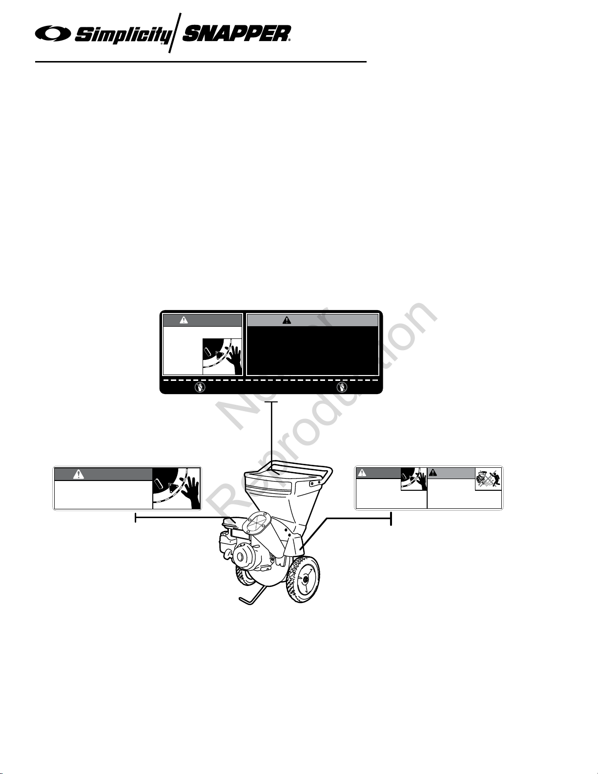
Safety Decals
This unit has been designed and manufactured to
provide you with the safety and reliability you would
expect from an industry leader in outdoor power
equipment manufacturing.
Although reading this manual and the safety instructions
it contains will provide you with the necessary basic
knowledge to operate this equipment safely and
effectively, we have placed several safety labels on the
unit to remind you of this important information while you
are operating your unit.
Decal - Operating Instructions,
North American Models
All DANGER, WARNING, CAUTION and instructional
messages on your unit should be carefully read and
obeyed. Personal bodily injury can result when these
instructions are not followed. The information is for your
safety and it is important! The safety decals below are on
your unit.
If any of these decals are lost or damaged, replace them
at once. See your local dealer for replacements.
These labels are easily applied and will act as a constant
visual reminder to you, and others who may use the
equipment, to follow the safety instructions necessary for
safe, effective operation.
Decal - Danger,
Rotating Cutting Blades,
North American Models
Decal - Danger,
Rotating Cutting Blades, Warning, Debris,
North American Models
Page 8
Page 9
1731919
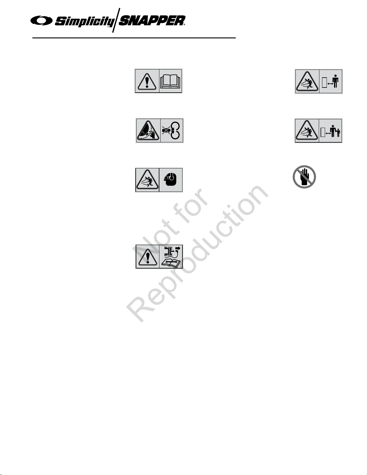
Safety Icons (European Models)
Not for
Reproduction
OPERATOR INSTRUCTIONS AND PARTS
1695924 Chipper/Shredder
Safety Rules and Information
Warning: Read Operator’s
Manual.
Read and understand the
Operator’s Manual before using this
machine.
Danger: Amputation Hazard.
To avoid serious personal injury from
rotating cutting blades, keep hands
out of inlet while machine is running.
Danger: Wear Appropriate Safety
Equipment.
This machine is capable of throwing
objects and debris. Always wear
safety goggles while operating.
This machine’s operating sound
power level is 109 dB(A) or more.
Wear hearing protection while
operating.
Danger: Thrown Objects.
This machine is capable of throwing
objects and debris. Keep bystanders
away.
Danger: Thrown Objects.
This machine is capable of throwing
objects and debris. Keep bystanders
and children away when engine is
running.
Danger: Do Not Place Hands in
the Machine.
To avoid serious personal injury from
rotating cutting blades, keep hands
out of inlet while machine is running.
Do not place hands in areas where
this symbol is present.
Warning: Disconnect the Spark
Plug Wire Before Servicing.
Disconnect the spark plug wire, and
secure it away from the spark plug
before servicing the unit.
Page 9
Page 10

Identification Numbers
Not for
Reproduction
When contacting your authorized dealer for
replacement parts, service, or information you
MUST have these numbers.
Record your model name/number, manufacturer’s
identification numbers, and engine serial numbers in the
space provided for easy access. These numbers can be
found in the locations shown.
NOTE: For location of engine identification numbers,
refer to the engine owner’s manual.
OPERATOR INSTRUCTIONS AND PARTS
1695924 Chipper/Shredder
Safety Rules and Information
ID Tag
PRODUCT REFERENCE DATA
Model Description Name/Number
Unit PART
Dealer Name
Engine Make
Engine Type/Spec
Number
Unit SERIAL Number
Date Purchased
ENGINE REFERENCE DATA
Engine Model
Engine Code/Serial Number
Page 10
Page 11

Initial Assembly
Not for
Reproduction
Install Chipper Cone - All Models
1 . Position the chipper cone (A) over the three 5/16-18
threaded studs protruding from the engine plate, and
attach using three 5/16-18 flange nuts (B).
2. Rotate cone and cone base a
cone does not contact engine.
3. Tighten the flange n
uts securely.
way from engine so
OPERATOR INSTRUCTIONS AND PARTS
1695924 Chipper/Shredder
Initial Assembly
A
B
Figure 18. Installing the Chipper Cone
A. Metal Cone Assembly
B. 5/18-18 Flange Nut
Page 11
Page 12

Install the Hopper - All Models
Not for
Reproduction
1. Remove two 1/4 locknuts and flat washers from
hopper liner and set aside. Attach the hopper to the
rotor housing. Make sure to engage the metal lip of
the hopper liner inside the housing.
2. Secure the hopper to the rotor housing using two
5/16 x 1/2 he
hardware removed from step 1 (Figure 19). Do not
tighten hardware at this time.
3. See Figure 20. F
one 5/16-18 x 3/4 hex head bolt, 5/16 lockwasher,
and 5/16 flat washer into each of the upper and lower
holes of the metal hopper liner. Finger tighten only at
this time.
4. Check that the hopper is seated correctly and tighten
all hardw
Install the Handle - All Models
1. Lift the hopper handle up until the outer holes in the
handle align with the holes in the shredder hopper
and secure with 1/4-20 x 3/4 screws, washers, and
nuts (A, Figure 21). Insert the screws from the
outside of the shredder hopper.
x head bolts, two 5/16 flat washers and
rom the inside of the hopper install
are.
OPERATOR INSTRUCTIONS AND PARTS
1695924 Chipper/Shredder
Initial Assembly
Figure 20. Installing Hardware Inside the Hopper
A
Figure 19. Attaching the Hopper
Page 12
Figure 21. Installing the Hopper Handle
A. 1/4-20 x 3/4 Screw & Nut
Page 13

Pull drawstring tight.
Lift discharge
chute and slide
bag over chute.
Make sure bag
noose fits over
top of discharge
chute and notch
in chute bottom.
Pull drawstring tight.
Slide bag over discharge chute.
Make sure bag
noose fits over top
of discharge chute
and notch in chute
bottom.
Not for
Reproduction
OPERATOR INSTRUCTIONS AND PARTS
1695924 Chipper/Shredder
Initial Assembly
Figure 22. Discharge Bag - North American Models
Install Discharge Bag
This product comes with a discharge bag for collection of
debris as it exits the discharge chute. Install the bag as
shown in Figure 22 or 23.
Add Engine Oil
Refer to “Engine Oil Type and Capacity” in the Regular
Maintenance section for oil type and fill procedures.
Add Fuel
Refer to “Adding Fuel” in the Operation section for fuel
specifications and filling procedures.
Figure 23. Discharge Bag - CE Models
Page 13
Page 14

OPERATOR INSTRUCTIONS AND PARTS
Not for
Reproduction
1695924 Chipper/Shredder
Features and Controls
Figure 1. Controls
Control Functions
The information below briefly describes the function of individual controls. Operating requires the combined use of
several controls applied in specific sequences. To learn what combination and sequence of controls to use for various
tasks see the OPERATION section.
the engine starts. A warm engine may not require
Engine Stop / Throttle Control
The engine stop / throttle control lever controls turn
the engine off and controls the engine speed. Move
the throttle right to increase engine speed and left to
decrease engine speed. Moving the lever all the way
to the left stops the engine. Always operate at FULL
throttle (lever fully right).
Recoil Starter
The recoil starter is used to turn the engine over for
starting.
Fuel Shut-Off Valve
The fuel shut-off valve is located below the air cleaner
housing. Always close the valve when the unit is not in
use.
Choke
Close the choke for cold starting. Open the choke once
choking. Move the lever right to close the choke.
Fuel Tank
To remove the cap, turn counterclockwise.
Chipper Cone / Shredder Hopper
Chipper Cone: The chipper cone is located on the front
of the unit next to the engine. Insert branches and tree
limbs up to approximately 3” (7.6 cm) in diameter into the
chipper cone. NEVER insert hands past the mouth of
the cone.
Shredder
unit. Leaves and other light waste can be loaded into the
shredder hopper. NEVER insert hands into the hopper .
Debris Ba
discharged from the unit. Do not operate the unit without
the debris bag in place.
Hopper: The shredder hopper is on top of the
g: Use the debris bag to collect the material
Page 14
14
Page 15

OPERATOR INSTRUCTIONS AND PARTS
Not for
Reproduction
1695924 Chipper/Shredder
Operation
General Operating Safety
Be sure to read all information in the Safety and
Operation sections before attempting to operate this unit.
Become familiar with all of the controls and how to stop
the unit.
Upon start-up and shut-down, you may hear the
metal-to-metal sound of the triangular hammers and Jhammers positioning themselves on the rotor. This is
normal. If this sound continues after the machine has
reached full speed, contact your dealer for an inspection
of the unit. Overloading the equipment will shorten its
life, and can cause mechanical failures.
Chipper Operation
The chipper is designed to handle tree limbs and
branches up to approximately 3” (7,6 cm) in diameter.
The chipping knives also permit the processing of course
organic matter like corn stalks. Tree branches must be
inserted large-end first into the chipper cone. Since
occasional kick-backs may occur, always stand off to the
side of the unit. Allow the self-feeding action of the unit
to draw the sticks in.
Shredder Operation
The shredder is designed to shred light brush, leaves,
and other soft but bulky organic waste. As material is
loaded into the shredder hopper it is pulled into the path
of the triangular and J-hammers by air flow.
Vacuum Attachment (Optional)
DANGER
The exhaust from this product contains carbon
monoxide gas. Carbon monoxide is a colorless,
orderless, and tasteless gas that can cause
dizziness, nausea, unconsciousness, or even
brain damage and death if inhaled for prolonged
periods.
Operate the unit outdoors in a well ventilated
location only. Keep children, pets, and bystanders
away.
Failure to follow these instructions may result in
serious injury or death.
Adding Fuel
Do not use gasoline containing METHANOL,
gasoh o l conta i n ing mo r e than 1 0 %
ETHANOL, gasoline additives, or white gas
because engine/fuel system damage could
result.
WARNING
Gasoline is highly flammable and must be handled
with care. Never fill the tank when the engine is
still hot
flame, smoking or matches in the area. Avoid
over-filling and wipe up any spills.
from recent operation. Do not allow open
WARNING
To avoid serious personal injury from rotating
cutting blades, keep hands out of inlet while
machine is running.
In addition to the chipper cone and hopper, loose debris
may be processed by the Vacuum hose adapter kit.
Leaves may be raked directly into the leaf tray where
vacuum action will draw them into the shredder. For
hard-to-reach areas, the nozzle and hose assembly may
be used. The strength of the Vacuum may be changed
using the rotating sleeve on the nozzle.
Operating Location
Select an area with firm, level ground, covered by dirt or
grass. Do not operate on wet or slick surfaces, or near
bystanders. Locate and organize the materials to be
processed so that you don’t have to walk in front of the
inlet or discharge openings, and so you have adequate
room to work safely.
To add fuel:
1. Remove the fuel cap (see Figure 1).
2. Fill the tank. Do not overfill. Leave room in the tank
for fuel expansion. Refer to your engine manual for
specific fuel recommendations.
3. Install and hand tighten the fuel cap.
Starting the Engine
1. Set the throttle to FULL.
2. Close the choke.
NOTE: A warm engine may not require choking.
3. Place one foot on the front suppor
unit firmly in place.
4. Pull the starting rope out to begin tur
over. Pull slowly at first and increase speed with
each successive pull.
5. After the engine starts
engine throttle control to SLOW. Warm up the engine
, open the choke and move the
t leg to hold the
ning the engine
Page 15
Page 16

by running it for at least a minute.
Not for
Reproduction
6. Set throttle to FULL and begin chipping/shredding.
Stopping the Engine
NOTE: In the event of an emergency the engine can be
stopped by setting the throttle control to STOP.
1. Slide the throttle control fully left to the
position.
STOP
NOTE: Upon start-up and shut-down, you may hear the
metal-to-metal sound of the triangular hammers and Jhammers positioning themselves on the rotor. This is
normal.
2. After the engine has stopped moving, remo
spark plug wire and remove any debris from the unit
and engine.
ve the
Processing Materials
Most materials to be processed can be handled more
efficiently by following these tips.
Chipping Tips:
• Prune branches down close to the main branch to
make feeding them into the chipper cone easier.
• Large
• If the mater
• If additional f
• Maintain control of the mater
• Do not inser
, hard, dried tree branches that resist chipping
can be processed by rotating them as you alternately
insert and retract them.
ial to be chipped is extremely hard, kicks
back forcefully when being fed into the chipper cone,
or cannot be easily controlled, remove the material
immediately and set it aside.
orce is required to insert materials
into the chipper, the blades probably need to be
sharpened. Consult the Troubleshooting and Repair
section of this manual, or see your authorized dealer.
ials you are feeding to
prevent them from whipping around.
t short pieces of material into the chipper
cone by hand. Use a larger piece of material to force
them into the chipper cone.
OPERATOR INSTRUCTIONS AND PARTS
1695924 Chipper/Shredder
Operation
Figure 2. Chipping.
Shredding Tips
• Don’t overload the shredder by dumping large
volumes of material into the hopper opening.
• Alternate loads of wet and dry material to prevent the
discharge from becoming plugged.
ver use any object to force material into the
• Ne
shredding chamber. It could get caught in the
shredding hammers and damage the unit.
Page 16
Figure 3. Shredding.
Page 17

OPERATOR INSTRUCTIONS AND PARTS
Not for
Reproduction
Chipping & Shredding Recommendations
1695924 Chipper/Shredder
Operation
Operation Type of Waste
Permitted
Shredding Dry or moist organic
material including leaves,
plants, flowers, fruits, or
vegetables.
Chipping Long, thicker tree limbs or
small bunches of smaller
sticks grouped together for
ease of handling.
Vacuum
Attachment
Light, loose, dry waste such
as leaves, grass clippings,
or sawdust.
Size Limitations Notes
Branches and twigs up to
1/2” diameter and 18” long.
Tree limbs and branches,
or bundles of small sticks
grouped for easier handling.
Maximum diameter of
approximately 3” (7,6 cm).
Small materials that will not
obstruct the vacuum hose.
Alternately chip or shred moist green
waste with dry waste to avoid plugging
of the discharge chute.
Process at a feeding rate that allows the
rotor to keep up and maintain a high rate
of speed.
Bulky tree limbs should be pruned close
to the main stem. Always use a shorter
piece of wood to push end pieces into
the chipper cone. Never place hands in
the chipper cone.
Never chip very hard or dry materials
such as kiln dried dimensional lumber
(2x4’s etc.) or other building materials.
Never use the chipper to process
pressure-treated wood products.
The vacuum is engineered for small,
loose waste and for cleaning around
decorative landscaping and flower
beds. Twigs, wet leaves, and other bulky
materials will clog the hose or obstruct
the shredding chamber.
Storage
Before you store your unit for the off-season, read the
Maintenance and Storage instructions in the Safety
Rules section, then perform the following steps:
erform engine maintenance and storage measures
• P
listed in the engine owner’s manual. This includes
draining the fuel system, or adding stabilizer to
the fuel (do not store a fueled unit in an enclosed
structure - see warning).
Before starting the unit after it has been stored:
• Chec
• Perform all recommended checks and procedures
• Allo
k all fluid levels. Check all maintenance items.
found in the engine owner’s manual.
w the engine to warm up for several minutes
before use.
Page 17
Page 18

Regular Maintenance
Not for
Reproduction
Maintenance Schedule & Procedures
The following schedule should be followed for normal care of your unit.
OPERATOR INSTRUCTIONS AND PARTS
1695924 Chipper/Shredder
SAFETY ITEMS Before
Each
Use
Check for loose hardware • •
Check all safety labels •
Inspect cone, hopper, and guards. •
CHIPPER MAINTENANCE ITEMS Before
Each
Use
Clean debris from engine and chipper. ** • •
Inspect/Rotate Shredding Hammers •
Inspect/Rotate Chipping Knives
ENGINE MAINTENANCE ITEMS Before
Each
Use
Check Engine Oil Level * • •
Change Engine Oil * **
Check / Change Engine Air Filter * **
Replace Spark Plug *
Every 5
Hours
Every 5
Hours
Every 8
Hours
Every 25
Hours
Every 25
Hours
•
Every 25
Hours
•
Every
100
Hours
Every
100
s
Hour
Every 50
Hours
•
Every
250
Hours
Every
250
s
Hour
Every
100
Hours
•
Spring &
Fall
Spring &
Fall
Spring &
Fall
* Refer to engine owner’s manual. Change original engine oil after initial break-in period of 5-8 hours.
** More often in hot (over 85° F: 30° C) weather or dusty operating conditions.
Check for Loose Hardware
Service Interval: Every 5 hours; every spring and fall.
Inspect the unit, checking for loose hardware or
components. Pay special attention to the hardware
attaching the chipper cone, hopper, axle, and front leg.
Inspect Cone, Hopper, & Guards
Service Interval: Every spring and fall.
Check that the chipper cone, shredder hopper, and
discharge guards are in place, undamaged, and secure.
Replace any damaged or missing parts.
Check Safety Labels
Service Interval: Every spring and fall.
Check that the safety labels are in place and
undamaged. Sample illustrations and part numbers
of the decals can be found on page 6. Replace any
damaged or missing decals.
Page 18
Page 19

OPERATOR INSTRUCTIONS AND PARTS
Not for
Reproduction
1695924 Chipper/Shredder
Regular Maintenance
A
Figure 4. Clean Debris from Engine Cooling Fins
Clean Debris from Engine &
Chipper
Service Interval: Before each use and every 100
hours.
The engine requires air flow to cool itself and for
combustion. Before each use, clean any debris from the
unit especially from around the air shroud intake, air filter,
and muffler. Every 100 hours, remove the engine air
shroud and clean out any debris from the engine cooling
fins at the locations shown in Figure 4. We recommend
having this service performed by an authorized dealer.
Inspect / Rotate Shredding
Hammers
Service Interval: Every 25 Hours, or As Necessary
The shredding hammers of this unit can be rotated to
provide a new cutting surface as required. The triangular
hammers can be rotated twice, then flipped over for a
total of 6 sharp cutting surfaces. The J-hammers can be
flipped over once. To inspect the shredding hammers:
Figure 5. Inspect Shredder Hammers
A. Access Panel
Figure 6. Triangular Hammer Wear Area
WARNING
Amputation hazard. To avoid serious injury from
accidental starting, always disconnect the spark
plug wire and secure it away from the spark plug
when servicing the unit.
1. Disconnect the spark plug wire and secure it a
from the spark plug.
2. Remov
from the back of the shredder housing.
3. Inspect the cutting edges of the triangular hammers
(Figure 6) and J-hammers (Figure 7).
e the small circular access panel (A, Figure 5)
way
Figure 7. J-Hammer Wear Area
To rotate or replace the shredding hammers, see the
Troub
leshooting and Repair section.
Page 19
Page 20

Inspect Chipping Knives
Not for
Reproduction
Service Interval: Every 25 Hours, or As Necessary
The chipping knives of this unit can be rotated or
sharpened to provide a new cutting surface as required.
When inspecting the knives be careful to avoid touching
the sharpened edges. To inspect the chipping knives:
1. Disconnect the spark plug wire and secure it a
from the spark plug.
way
WARNING
To avoid serious injury from accidental starting,
always disconnect the spark plug wire and secure
it away from the spark plug when servicing the unit.
2. See Figure 8. Remo
cone to the front of the chipper. Remove the chipper
cone (A) to access the knives.
3. Using the recoil starter
to rotate the rotor into position so the blades can be
seen.
To sharpen or replace the chipper knives, see the
leshooting and Repair section.
Troub
ve the nuts securing the chipper
, slowly pull the starter rope
OPERATOR INSTRUCTIONS AND PARTS
1695924 Chipper/Shredder
Regular Maintenance
A
Figure 8. Inspect Chipper Knives
A. Chipper Cone
Check / Change Engine Air
Cleaner
Service Interval: Every 25 Hours
The engine air cleaner assembly should be opened,
inspected, and the filter element replaced every 25 hours,
or as required if debris has built up in the assembly.
To replace the air filter and pre-cleaner assembly:
1. Loosen the scre
cover (B).
2. Inspect the pre-cleaner (C) and air filter element (D).
If either are soiled, then replace
3. Insert the ne
(D) inside the filter cover (B). Make sure the arrows
on the filter element are pointed up, and the lip of the
pre-cleaner covers the bottom filter pleats.
4. Insert the co
5. Tilt the cover up into place and tighten the screw (A).
w (A, Figure 9) and remo
.
w pre-cleaner (C) and air filter element
ver tabs (F) into the filter base slots.
ve the filter
Replace Spark Plug
Please contact your authorized dealer to perform this
service.
C
B
A
Figure 9. Change Air Filter. NOTE: This illustration
is for general reference only. Some engine models
may appear different. Refer to the engine manual for
more detailed instruction.
A. Screw
B. Filter Cover
C. Pre-Cleaner (Not included in some engine models)
D. Air Filter Element
E. Air Filter Base
F. Slots and Tabs
D
E
F
Page 20
Page 21

Engine Oil Type & Capacity
Use oil classified API Service Class SF,
SG, SH, SJ or better with SAE Viscosity:
10080604020 320-20
3827164-7
0-18-30
˚F
˚C
30 Conventional**
5W-30, 10W-30 Synthetic
5W-30
10W-30
Conventional*
*CAUTION: Air cooled engines run hotter than automotive engines.
The use of non-synthetic multi-viscosity oils (5W-30, 10W-30, etc.)
in temperatures above 40º F (4ºC) will result in higher than normal
oil consumption. When using a multi-viscosity oil, check oil level
more frequently.
**CAUTION: SAE 30 oil, if used below 40º F (4ºC), will result in hard
starting and possible engine bore damage due to inadequate
lubrication.
Not for
Reproduction
Select a quality engine oil using the chart in Figure 10.
8.5 torque rated models require 5/8 quart (0.6L) of oil.
Check Engine Oil Level
Service Interval: Before Each Use
Check the engine oil level at the oil fill and level check
plug (A, Figure 11).
1. Stop the engine and wait f
2. Remove the oil fill and level check plug (A, Figure 11)
by twisting it counter-clockwise. The oil should be
filled up to the mouth of the filler opening as shown in
the Figure 11 inset.
or all moving parts to stop.
Change Engine Oil
Service Interval: Every 50 Hours
1. Stop the engine and wait for all moving parts to stop.
Allow the unit to cool before changing the oil.
2. Remov
by twisting it counter-clockwise.
3. Place an oil drain pan belo
the oil drain plug (B, Figure 11). Allow the oil to drain
completely.
4. Reinstall the oil drain plug (B).
125 inch pounds (14 Nm)
5. Add oil to the oil fill hole (A) until the oil lev
with the bottom edge of the oil fill hole (Figure 11
inset).
e the oil fill and level check plug (A, Figure 11)
w the engine and remove
Tighten the plug to
el is even
OPERATOR INSTRUCTIONS AND PARTS
1695924 Chipper/Shredder
Regular Maintenance
Figure 10. Oil Recommendations
A
B
Figure 11. Oil Fill and Oil Drain
A. Oil Fill & Level Check Plug
B. Oil Drain Plug
Page 21
Page 22

OPERATOR INSTRUCTIONS AND PARTS
Not for
Reproduction
1695924 Chipper/Shredder
Troubleshooting & Repair
Troubleshooting Chart
While normal care and regular maintenance will extend
the life of your equipment, prolonged or constant use
may eventually require that service be performed to allow
it to continue operating properly.
The troubleshooting guide below lists the most common
problems, their causes, and remedies.
See the information on the following pages for
instructions on how to perform most of these minor
adjustments and service repairs yourself. If you prefer,
all of these procedures can be performed for you by your
local authorized dealer.
PROBLEM CAUSE REMEDY
Engine will not start. 1. Out of fuel. Add fuel.
2. Spark plug wire disconnected. Reconnect spark plug wire.
3. Engine controls not set correctly. Refer to Starting in the Operation section.
4. Spark plug fouled. Remove the spark plug, clean or replace.
5. No compression. Recoil starter See your authorized dealer.
pulls with no resistance.
6. No spark. Ignition problem. See your authorized dealer.
7. Old or stale fuel. See your authorized dealer.
Engine exhaust is black. 1. Dirty air filter
2. Choke closed. Open choke.
Engine runs but no material is 1. Discharge chute clogged.
discharged. 2. Engine not running at full speed. Set throttle control to FAST.
Excessive branch vibration when 1. Chipper knives dull. Shar
chipping materials. 2. Tree limbs are extremely hard or Material is not suitable for chipping.
dried out.
Unusual noise or vibration when. 1. Rotor ov
processing material. mater
2. Hammers are broken, bent, or Check assembly. Tighten or replace as
loose. required.
3. Hammers frozen in place. Check for obstructions and debris. Repair as
necessary.
Vacuum not working. 1. Hopper lid not in place. Install lid.
2. Material too wet. Allow material to dry.
3. Hose not attached properly. Attach hose per instructions (see hose kit).
4. Hose obstructed or damaged. Clear blockage or replace.
5. Engine not running at full RPM. Set throttle control to FAST.
. Replace air filter. See engine manual.
erloaded with material. Allow unit to clear itself before adding more
WARNING
To avoid serious injury, perform maintenance on
the unit only when the engine is stopped.
Always disconnect the spark plug wire and
fasten it away from the plug before beginning the
maintenance, to prevent accidental starting of the
engine.
Clean out debris.
pen or replace chipper knives.
ial to the hopper.
Page 22
Page 23

OPERATOR INSTRUCTIONS AND PARTS
Not for
Reproduction
1695924 Chipper/Shredder
Troubleshooting & Repair
Figure 12. Removing the Shredder Hopper Figure 13. Removing the Rotor Housing
Repair
Shredding Hammer Rotation and
Replacement
The cutting edges of the shredding hammers may
eventually wear out requiring rotation of the hammer or
replacement if all cutting edges have been dulled.
Triangular hammers can be rotated twice after the first
edge dulls, then flipped over once and rotated again for a
total of 6 edges. J-hammers can be flipped over once for
a total of two cutting edges.
To rotate the shredding hammers:
1. T
n the engine off and wait for all moving parts to
ur
stop.
2. Disconnect the spark plug wire and secure it a
from the spark plug.
way
WARNING
To avoid serious injury from accidental starting,
always disconnect the spark plug wire and secure
it away from the spark plug when servicing the unit.
3. Detach the shredder hopper from the rotor housing
(Figure 12).
4. Remov
that secures it to the main housing (Figure 13).
5. Note the assembly sequence of the hardw
secure the hammers (Figure 14). Using a 5/16” allen
wrench remove the socket head capscrew (A) and
related hardware.
6. Inspect the hammers (G, H), spacer tubes (D, F),
and hardw
of wear, replace it. Inspect and flip, or replace the
hammers (G, H).
7. Reassemble the hammers
e the rotor cover by removing the hardware
are used to
are. If the spacer tube (D, F) shows signs
, spacers, washers, and
F
E
F
H
E
Figure 14. Removing the Rotor Housing
A. Socket Hd. Capscrew E. Spacer, Short
B. Lockwasher, 3/8 F. Washer, 3/8 (8HP Only)
C. Washer, 7/8 G. J-Hammer
D. Spacer, Long H. Triangular Hammer
G
D
C
B
A
D
C
B
A
Page 23
Page 24

capscrews. Torque the socket head capscrews (A)
1/16”
Min
30°
Top View Side View
Not for
Reproduction
to 30-35 ft. lbs. (41-47 N.m.)Refer to Figure 14 for
assembly. The J-hammer (G) on the opposite side of
the rotor faces outward for balanced rotation.
Repeat for all the hammers.
Chipping Knives Sharpening and
Replacement
The chipping knives should be sharpened or replaced
when tree limbs require extra force to feed into the
chipper cone.
The chipping knives may be resharpened at a 30 degree
angle until the distance between the edge of the blade
bevel and the mounting hole is less than 1/16” (1.6mm)
(see Figure 17).
WARNING
Amputation hazard. To avoid serious injury from
accidental starting, always disconnect the spark
plug wire and secure it away from the spark plug
when servicing the unit.
OPERATOR INSTRUCTIONS AND PARTS
1695924 Chipper/Shredder
Troubleshooting & Repair
Figure 15. Installing the Chipper Cone
To inspect, sharpen, or replace the chipping knives:
1. T
n the engine off and wait for all moving parts to
ur
stop.
2. Disconnect the spark plug wire and secure it a
from the spark plug.
3. Detach the shredder hopper from the rotor housing
(see Figure 12).
4. Remov
that secures it to the main housing (see Figure 13).
e the rotor cover by removing the hardware
way
WARNING
Cutting hazard. To avoid serious injury, avoid
contacting the sharp cutting edges of the chipping
knives.
5. Remove the chipper cone base (Figure 15).
6. Rotate the rotor assembly so that the socket head
capscrews that secure one of the chipper knives can
be accessed through the rotor cover and access hole
(Figure 16).
7. Using a 1/4” hex wrench, loosen and remove the two
socket head capscrews and chipper knife.
8. Inspect, rotate, sharpen, or replace the chipper knife.
9. Reinstall the chipper knife and tighten the socket
head capscrews to 18-20 ft. lbs (24-27 N.m.).
10. Rotate the rotor 180 degrees and repeat with the
other chipper knife. Reinstall the rotor cover and
shredder hopper when completed.
A
Figure 16. Access Hole
A. Access Hole
Figure 17. Chipper Knife Minimum Cutting Edge
Page 24
Page 25

OPERATOR INSTRUCTIONS AND PARTS
Not for
Reproduction
1695924 Chipper/Shredder
Specifications
NOTE: Specifications are correct at time of printing and are subject to change without notice.
* Actual sustained equipment horsepower will likely be lower due to operating
limitations and environmental factors.
CHASSIS:
All Models
Chipping Capacity Approximately 3” (7.6 cm)
Shredding Capacity 1/2” x 18” Long
Chipping Knives 2
Shredding Hammers 2 J-hammers,
2 triangular hammers
Waste Reduction Ratio Approximately 20:1
eight Model 1695924: 8.50 Torque Rating 130 lbs.
W
Page 25
Page 26

OPERATOR INSTRUCTIONS AND PARTS
1737660 Rev B
BRIGGS & STRATTON POWER PRODUCTS GROUP, L.L.C. OWNER WARRANTY POLICY
LIMITED WARRANTY
Briggs & Stratton Power Products Group, LLC will repair and/or replace, free of charge, any part(s) of the equipment that is
defective in material or workmanship or both. Briggs & Stratton Corporation will repair and/or replace, free of charge, any
part(s) of the Briggs and Stratton engine* (if equipped) that is defective in material or workmanship or both. Transportation
charges on product submitted for repair or replacement under this warranty must be borne by purchaser. This warranty is
effective for the time periods and subject to the conditions stated below. For warranty service, find the nearest Authorized
Service Dealer using our dealer locator at www.BriggsandStratton.com or www.Murray.com.
There is no other express warranty. Implied warranties, including those of merchantability and fitness for a particular
purpose, are limited to one year from purchase or to the extent permitted by law. Liability for incidental or consequential
damages are excluded to the extent exclusion is permitted by law.
Some states or countries do not allow limitations on how long an implied warranty lasts, and some states or countries do
not allow the exclusion or limitation of incidental or consequential damages, so the above limitation and exclusion may not
apply to you. This warranty gives you specific legal rights and you may also have other rights which vary from state to state
or country to country.
WARRANTY PERIOD
The warranty period begins on the date of purchase by the first retail consumer or commercial end user, and continues for the
period of time stated above. “Consumer use” means personal residential household use by a retail consumer. “Commercial
use” means all other uses, including use for commercial, income producing or rental purposes. Once product has experienced
commercial use, it shall thereafter be considered as commercial use for purposes of this warranty.
No warranty registration is necessary to obtain warranty on Briggs & Stratton products. Save your proof of purchase receipt. If you
do not provide proof of the initial purchase date at the time warranty service is requested, the manufacturing date of the product will
be used to determine warranty eligibility.
ABOUT YOUR WARRANTY
We welcome warranty repair and apologize to you for being inconvenienced. Warranty service is available only through servicing
dealers authorized by Briggs & Stratton or BSPPG, LLC.
Most warranty repairs are handled routinely, but sometimes requests for warranty service may not be appropriate. This warranty
only covers defects in materials or workmanship. It does not cover damage caused by improper use or abuse, improper
maintenance or repair, normal wear and tear, or stale or unapproved fuel.
Improper Use and Abuse - The proper, intended use of this product is described in the Operator’s Manual. Using the product in
a way not described in the Operator’s Manual or using the product after it has been damaged will void your warranty. Warranty is
not allowed if the serial number on the product has been removed or the product has been altered or modified in any way, or if the
product has evidence of abuse such as impact damage, or water/chemical corrosion damage.
Improper Maintenance or Repair - This product must be maintained according to the procedures and schedules provided in the
Operator’s Manual, and serviced or repaired using genuine Briggs & Stratton parts. Damage caused by lack of maintenance or use
of non-original parts is not covered by warranty.
Normal Wear - Like all mechanical devices, your unit is subject to wear even when properly maintained. This warranty does not
cover repairs when normal use has exhausted the life of a part or the equipment. Maintenance and wear items such as filters,
belts, cutting blades, and brake pads (engine brake pads are covered) are not covered by warranty due to wear characteristics
alone, unless the cause is due to defects in material or workmanship.
Stale Fuel - In order to function correctly, this product requires fresh fuel that conforms to the criteria specified in the Operator’s
Manual. Damage caused by stale fuel (carburetor leaks, clogged fuel tubes, sticking valves, etc) is not covered by warranty.
* Applies to Briggs and Stratton engines only. Warranty coverage of non-Briggs and Stratton engines is provided by the engine manufacturer.
Item Consumer Use Commercial Use:
Equipment 2 Years 90 Days
Engine* 2 Years 90 Days
Battery 1 Year 1 Year
EN
Not for
Reproduction
1695924 Chipper/Shredder
Page 26
Page 27

OPERATOR INSTRUCTIONS AND PARTS
Not for
Reproduction
1695924 Chipper/Shredder
Page 27
Page 28

www.simplicitymfg.com
Not for
Reproduction
www.snapper.com
Briggs & Stratton Power Products Group, L.L.C.
Copyright © 2011 Briggs & Stratton Corporation
Milwaukee, WI USA. All Rights Reserved
www.BRIGGSandSTRATTON.com
 Loading...