


Model No. 130.288370
LT=125 Series Hydro Tractor
Mfg. No. Description
2690826 LT23420, 23HP & 42" Mower Deck
1737502
Revision
Rev. Date 02/2009

Product identification Tag
IIIIIIIIIIIIIlllIIII!11111IllIIIIIIIIIIIIIIIIIII
Model / ModUle / Model xxxxxxxx
lillilllilllllllIIIIIIIIIIIIIIIIIIlillilllIIIlilllllllllllIII
Serial / Serie / Serie xxxxxxxxxx
Briggs & Stratton Power Products Group, L.L.C.
Milwaukee, WI 53201 USA
When contacting your authorized dealer for replace-
ment parts, service, or information you MUST have
these numbers.
Record your model name/number, manufacturer's identi-
fication numbers, and engine serial numbers inthe
space provided for easy access. These numbers can be
found in the locations shown.
/!
Tractor ID Tag
Model Description Name/Number
Unit MFGNumber Unit SERIALNumber
Mower Deck MFG Number Mower Deck SERIALNumber
Dealer Name Date Purchased
Engine Make
EngineType/Spec
Engine Model
Engine Code/Serial Number

(ableofContents
Operator Safety .................................................... 4
Features & Controls .......................................... 10
Control Functions .................................................. 10
Operation ........................................................... 12
General Operating Safety ..................................... 12
Check & Fill Engine Oil ......................................... 12
Adding Fuel ........................................................... 12
Starting the Engine ............................................... 12
Parking Brake Function ......................................... 13
Cruise Control Operation ...................................... 13
Seat Adjustment .................................................... 13
Stopping the Tractor & Engine .............................. 14
Driving the Tractor ................................................ 14
Mowing .................................................................. 14
Mowing in Reverse ............................................... 14
Attachment Operation in Reverse ......................... 14
Pushing the Tractor by Hand ................................ 14
Adjusting Mower Cutting Height ............................ 15
Attaching a Trailer ................................................. 15
Maintenance ....................................................... 16
Maintenance Schedule ......................................... 16
Check Tire Pressure ............................................. 16
Check Safety Interlock System ............................. 17
Check Blade Brake ............................................... 17
Engine Maintenance ............................................. 17
Battery Maintenance ............................................. 18
Lubrication ............................................................ 18
Servicing the Mower Blades ................................. 20
Mower Deck Removal & Installation ..................... 21
Oil Drain Valve Operation ..................................... 22
Change Engine Oil ................................................ 22
Change Engine Oil & Filter ................................... 22
Air Filter & Pre-Cleaner Service ............................ 23
Replace Spark Plug .............................................. 23
Battery Charging ................................................... 24
Brake Adjustment .................................................. 24
PTO Clutch Adjustment ........................................ 24
Fuse Replacement ................................................ 25
Mower Adjustments .............................................. 25
Gauge Wheels .............................................. 25
Leveling the Mower ....................................... 26
Mower Belt Replacement ...................................... 26
Storage ................................................................. 27
Troubleshooting ................................................ 28
Troubleshooting the Tractor .................................. 28
Troubleshooting the Mower .................................. 29
Specifications .................................................... 30
3
perator
g
Congratulations on purchasing a superior-quality piece of lawn and
garden equipment. Our products are designed and manufactured to
meet or exceed all industry standards for safety.
Power equipment is only as safe as the operator. If it is misused, or
not properly maintained, it can be dangerous! Remember, you are
responsible for your safety and that of those around you.
Use common sense, and think through what you are doing. Ifyou
are not sure that the task you are about to perform can be safely
done with the equipment you have chosen, ask a
professional: contact your local authorized dealer.
RI
The operator's manual contains important safety information you need to be aware of
BEFORE you operate your unit as well as DURING operation.
Safe operating techniques, an explanation of the product's features and
controls, and maintenance information is included to help you get the
most out of your equipment investment.
Be sure to completely read the Safety Rules and Information found on
the following pages. Also completely read the Operation section.
in
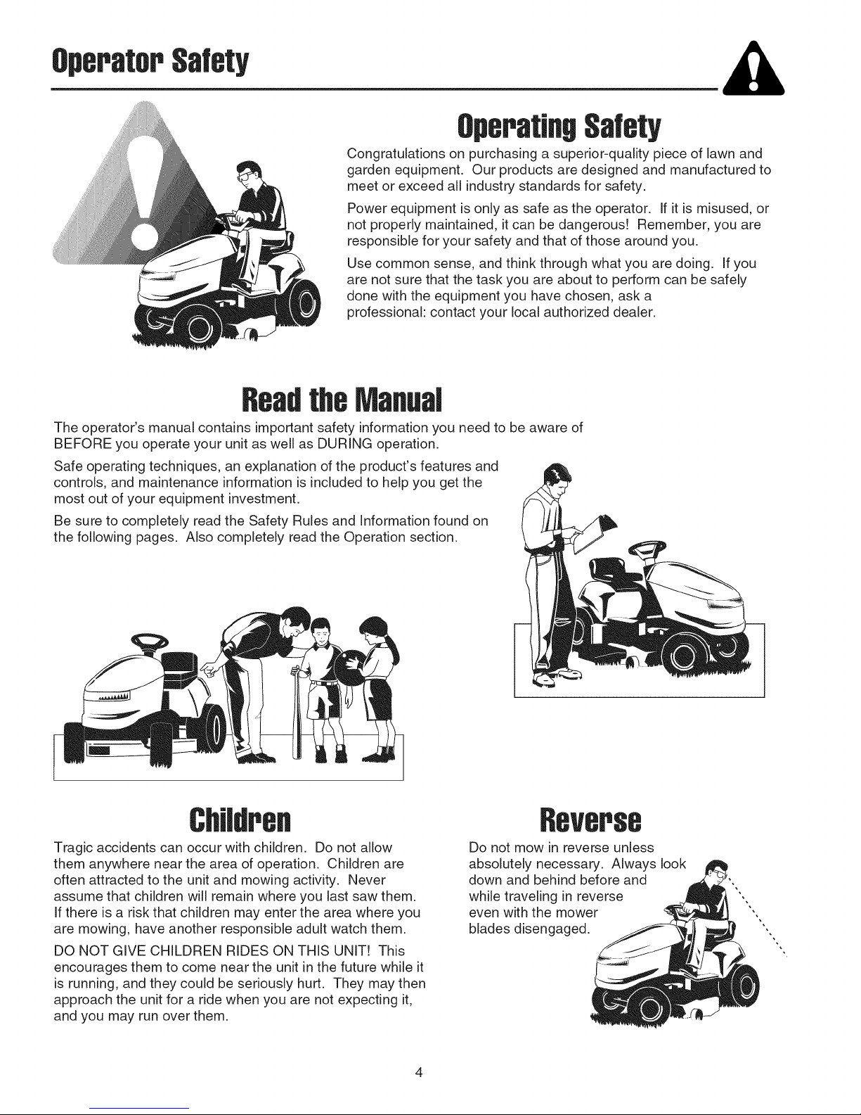
Tragic accidents can occur with children. Do not allow
them anywhere near the area of operation. Children are
often attracted to the unit and mowing activity. Never
assume that children will remain where you last saw them.
If there is a risk that children may enter the area where you
are mowing, have another responsible adult watch them.
DO NOT GIVE CHILDREN RIDES ON THIS UNIT! This
encourages them to come near the unit in the future while it
is running, and they could be seriously hurt. They may then
approach the unit for a ride when you are not expecting it,
and you may run over them.
RSVSP88
Do not mow in reverse unless
absolutely necessary. Always look
down and behind before and
while traveling in reverse
even with the mower
blades disengaged.
4
,peOperation
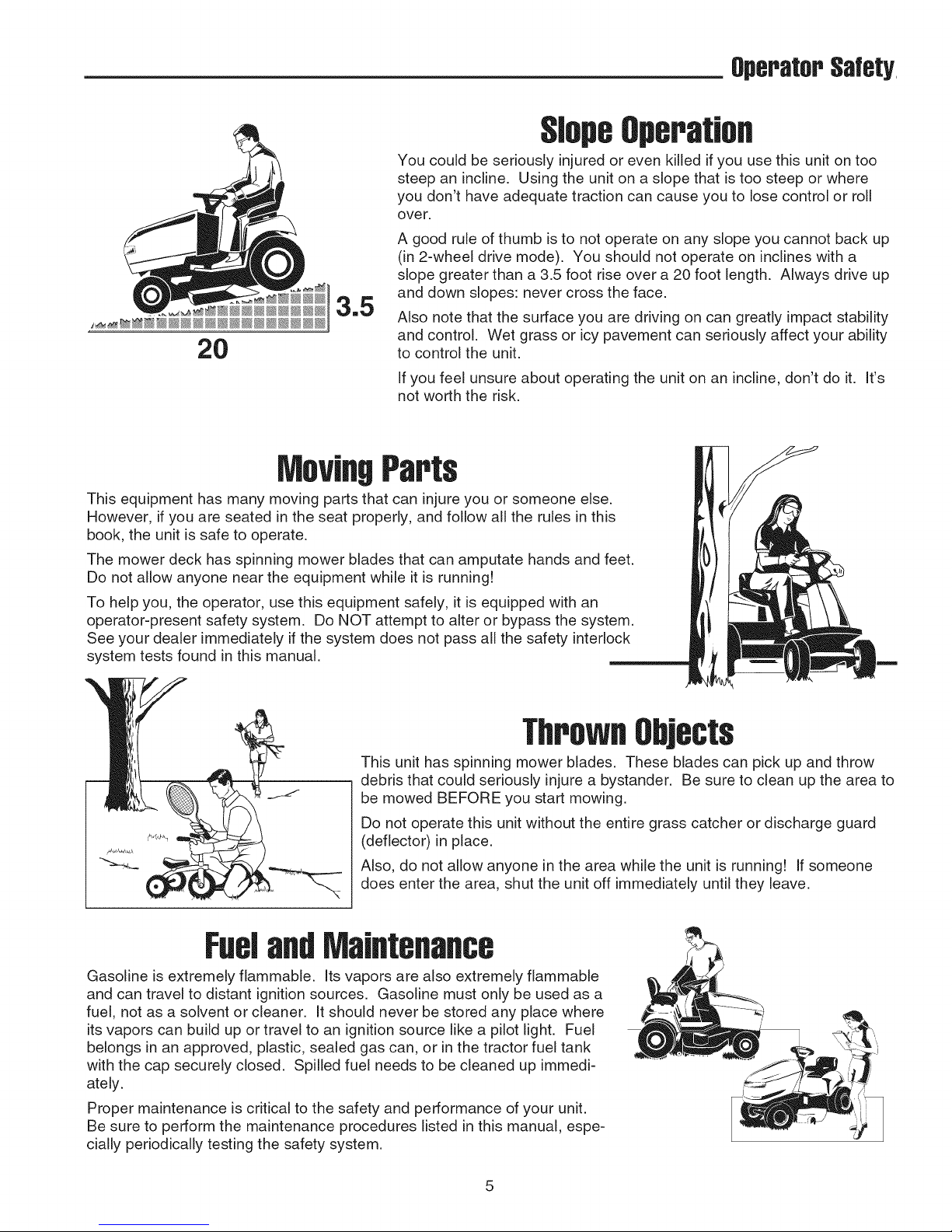
You could be seriously injured or even killed if you use this unit on too
steep an incline. Using the unit on a slope that is too steep or where
you don't have adequate traction can cause you to lose control or roll
over.
A good rule of thumb is to not operate on any slope you cannot back up
(in 2-wheel drive mode). You should not operate on inclines with a
slope greater than a 3.5 foot rise over a 20 foot length. Always drive up
3.5
2O
and down slopes: never cross the face.
Also note that the surface you are driving on can greatly impact stability
and control. Wet grass or icy pavement can seriously affect your ability
to control the unit.
If you feel unsure about operating the unit on an incline, don't do it. It's
not worth the risk.
Moving
This equipment has many moving parts that can injure you or someone else.
However, if you are seated inthe seat properly, and follow all the rules in this
book, the unit is safe to operate.
The mower deck has spinning mower blades that can amputate hands and feet.
Do not allow anyone near the equipment while it is running!
To help you, the operator, use this equipment safely, it is equipped with an
operator-present safety system. Do NOT attempt to alter or bypass the system.
See your dealer immediately if the system does not pass all the safety interlock
system tests found in this manual.
OperatorSafety,
Thrown ects
This unit has spinning mower blades. These blades can pick up and throw
debris that could seriously injure a bystander. Be sure to clean up the area to
be mowed BEFORE you start mowing.
Do not operate this unit without the entire grass catcher or discharge guard
(deflector) in place.
Also, do not allow anyone in the area while the unit is running! If someone
does enter the area, shut the unit off immediately until they leave.
Gasoline is extremely flammable. Its vapors are also extremely flammable
and can travel to distant ignition sources. Gasoline must only be used as a
fuel, not as a solvent or cleaner. It should never be stored any place where
its vapors can build up or travel to an ignition source like a pilot light. Fuel
belongs in an approved, plastic, sealed gas can, or in the tractor fuel tank
with the cap securely closed. Spilled fuel needs to be cleaned up immedi-
ately.
Proper maintenance is critical to the safety and performance of your unit.
Be sure to perform the maintenance procedures listed in this manual, espe-
cially periodically testing the safety system.
5
OperatorSafety
Read these safety rules and follow them closely. Failure to obey these rules could result in loss of control
of unit, severe personal injury or death to you, or bystanders, or damage to property or equipment.
This mowing deck is capable of amputating hands and feet and throwing objects.
The triangle _ in text signifies important cautions or warnings which must be followed.
GENERAL OPERATION
= Read, understand, and follow all instructions in the
manual and on the unit before starting.
Do not put hands or feet near rotating parts or under
the machine. Keep clear of the discharge opening at
all times.
= Only allow responsible adults, who are familiar with
the instructions, to operate the unit (local regulations
can restrict operator age).
= Clear the area of objects such as rocks, toys, wire,
etc., which could be picked up and thrown by the
blade(s).
= Be sure the area is clear of other people before mow-
ing. Stop the unit ifanyone enters the area.
= Never carry passengers.
= Do not mow in reverse unless absolutely necessary.
Always look down and behind before and while travel-
ling in reverse.
= Never direct discharge material toward anyone.
Avoid discharging material against a wall or obstruc-
tion. Material may ricochet back toward the operator.
Stop the blade(s) when crossing gravel surfaces.
Do not operate the machine without the entire grass
catcher, discharge guard (deflector), or other safety
devices in place.
• Slow down before turning.
• Never leave a running unit unattended. Always disen-
gage the PTO, set parking brake, stop engine, and
remove keys before dismounting.
• Disengage blades (PTO) when not mowing. Shut off
engine and wait for all parts to come to a complete
stop before cleaning the machine, removing the grass
catcher, or unclogging the discharge guard.
• Operate the machine only in daylight or good artificial
light.
• Do not operate the unit while under the influence of
alcohol or drugs.
• Watch for traffic when operating near or crossing
roadways.
Use extra care when loading or unloading the unit
into a trailer or truck.
Always wear eye protection when operating this unit.
Data indicates that operators, age 60 years and
above, are involved in a large percentage of power
equipment-related injuries. These operators should
evaluate their ability to operate the equipment safely
enough to protect themselves and others from injury.
Follow the manufacturer's recommendations for
wheel weights or counterweights.
Keep in mind the operator is responsible for accidents
occurring to other people or property.
All drivers should seek and obtain professional and
practical instruction.
Always wear substantial footwear and trousers.
Never operate when barefoot or wearing sandals.
Before using, always visually check that the blades
and blade hardware are present, intact, and secure.
Replace worn or damaged parts.
Disengage attachments before: refueling, removing
an attachment, making adjustments (unless the
adjustment can be made from the operator's posi-
tion).
When the machine is parked, stored, or left unattend-
ed, lower the cutting means unless a positive
mechanical lock is used.
Before leaving the operator's position for any reason,
engage the parking brake (if equipped), disengage
the PTO, stop the engine, and remove the key.
To reduce fire hazard, keep the unit free of grass,
leaves, & excess oil. Do not stop or park over dry
leaves, grass, or combustible materials.
It is a violation of California Public Resource Code
Section 4442 to use or operate the engine on or near
any forest-covered, brush-covered, or grass-covered
land unless the exhaust system is equipped with a
spark arrester meeting any applicable local or state
laws. Other states or federal areas may have similar
laws.
TRANSPORTING AND STORAGE
= When transporting the unit on an open trailer, make
sure it is facing forward, in the direction of travel. If
the unit is facing backwards, wind lift could damage
the unit.
Always observe safe refueling and fuel handling prac-
tices when refueling the unit after transportation or
storage.
Never store the unit (with fuel) in an enclosed poorly
ventilated structure. Fuel vapors can travel to an
ignition source (such as a furnace, water heater, etc.)
and cause an explosion. Fuel vapor is also toxic to
humans and animals.
Always follow the engine manual instructions for
storage preparations before storing the unit for both
short and long term periods.
Always follow the engine manual instructions for
proper start-up procedures when returning the unit to
service.
Never store the unit or fuel container inside where
there is an open flame or pilot light, such as in a
water heater. Allow unit to cool before storing.
OperatorSalety
SLOPE OPERATION
Slopes are a major factor related to loss-of-control and tip-
over accidents, which can result in severe injury or death.
Operation on all slopes requires extra caution. If you can-
not back up the slope or ifyou feel uneasy on it, do not
operate on it.
Control of a walk-behind or ride-on machine sliding on a
slope will not be regained by the application of the brake.
The main reasons for loss of control are: insufficient tire
grip on the ground, speed too fast, inadequate braking, the
type of machine is unsuitable for its task, lack of awareness
of the ground conditions, incorrect hitching and load distrib-
ution.
Mow up and down slopes, not across.
Watch for holes, ruts, or bumps. Uneven terrain could
overturn the unit. Tall grass can hide obstacles.
Choose a slow speed so that you will not have to
stop or change speeds while on the slope.
Do not mow on wet grass. Tires may loose traction.
Always keep unit in gear especially when traveling
down slopes. Do not shift to neutral and coast down-
hill.
Avoid starting, stopping, or turning on a slope. If tires
lose traction, disengage the blade(s) and proceed
slowly straight down the slope.
Keep all movement on slopes slow and gradual. Do
not make sudden changes in speed or direction,
which could cause the machine to rollover.
Use extra care while operating machines with grass
catchers or other attachments; they can affect the
stability of the unit. Do not use on steeps slopes.
Do not try to stabilize the machine by putting your
foot on the ground (ride-on units).
Do not mow near drop-offs, ditches, or embank-
ments. The mower could suddenly turn over if a
wheel is over the edge of a cliff or ditch, or if an edge
caves in.
Do not use grass catchers on steep slopes.
Do not mow slopes you cannot back up them.
See your authorized dealer/retailer for recommenda-
tions of wheel weights or counterweights to improve
stability.
• Remove obstacles such as rocks, tree limbs, etc.
• Use slow speed. Tires may lose traction on slopes
even through the brakes are functioning properly.
• Do not turn on slopes unless necessary, and then,
turn slowly and gradually downhill, if possible.
WARNING
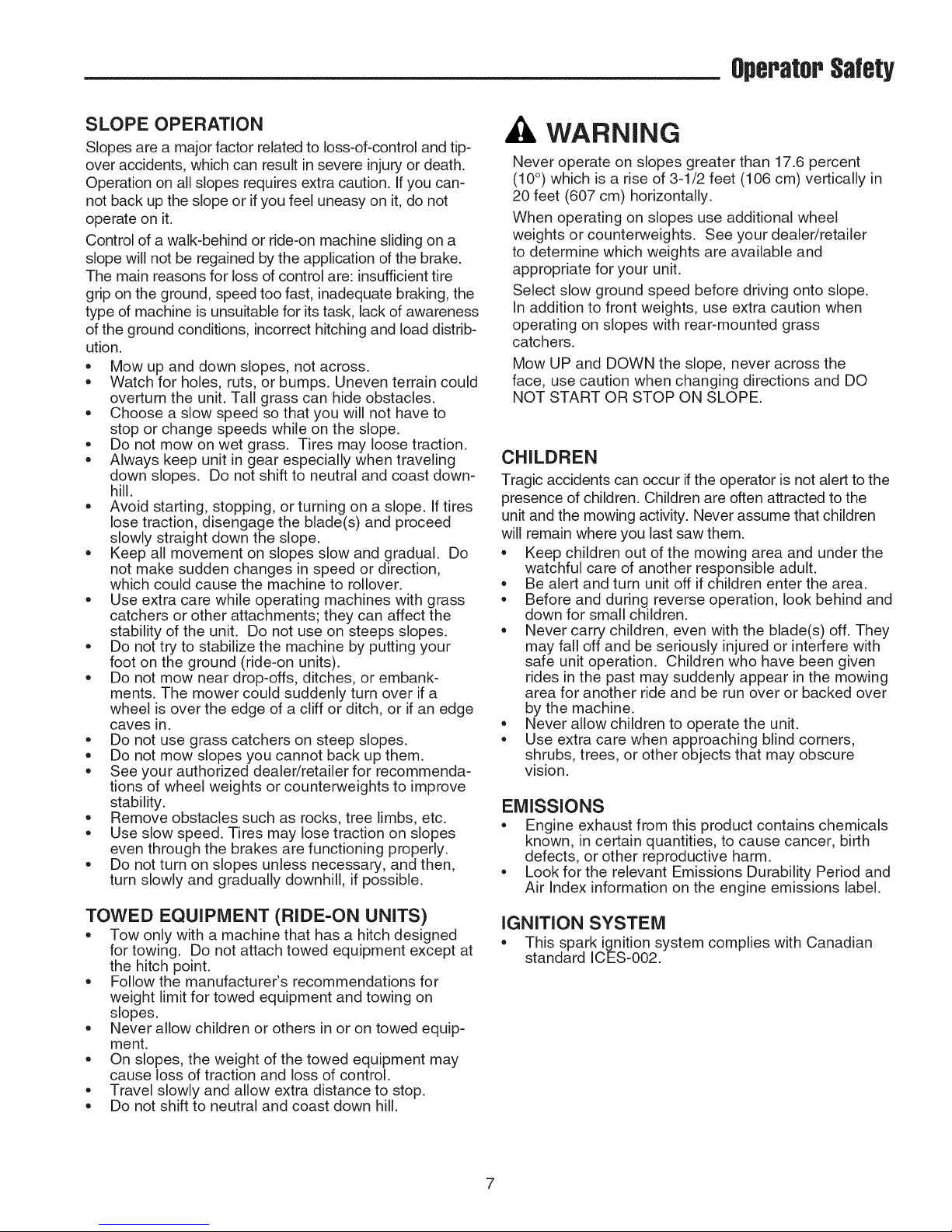
Never operate on slopes greater than 17.6 percent
(10°) which is a rise of 3-1/2 feet (106 cm) vertically in
20 feet (607 cm) horizontally.
When operating on slopes use additional wheel
weights or counterweights. See your dealer/retailer
to determine which weights are available and
appropriate for your unit.
Select slow ground speed before driving onto slope.
In addition to front weights, use extra caution when
operating on slopes with rear-mounted grass
catchers.
Mow UP and DOWN the slope, never across the
face, use caution when changing directions and DO
NOT START OR STOP ON SLOPE.
CHILDREN
Tragic accidents can occur if the operator is not alert to the
presence of children. Children are often attracted to the
unit and the mowing activity. Never assume that children
will remain where you last saw them.
Keep children out of the mowing area and under the
watchful care of another responsible adult.
Be alert and turn unit off if children enter the area.
Before and during reverse operation, look behind and
down for small children.
Never carry children, even with the blade(s) off. They
may fall off and be seriously injured or interfere with
safe unit operation. Children who have been given
rides in the past may suddenly appear in the mowing
area for another ride and be run over or backed over
by the machine.
Never allow children to operate the unit.
Use extra care when approaching blind corners,
shrubs, trees, or other objects that may obscure
vision.
EMISSIONS
Engine exhaust from this product contains chemicals
known, in certain quantities, to cause cancer, birth
defects, or other reproductive harm.
Look for the relevant Emissions Durability Period and
Air Index information on the engine emissions label.
TOWED EQUIPMENT (RIDE-ON UNITS)
Tow only with a machine that has a hitch designed
for towing. Do not attach towed equipment except at
the hitch point.
Follow the manufacturer's recommendations for
weight limit for towed equipment and towing on
slopes.
Never allow children or others in or on towed equip-
ment.
On slopes, the weight of the towed equipment may
cause loss of traction and loss of control.
Travel slowly and allow extra distance to stop.
Do not shift to neutral and coast down hill.
IGNITION SYSTEM
= This spark ignition system complies with Canadian
standard ICES-O02.
7
OperatorSafety
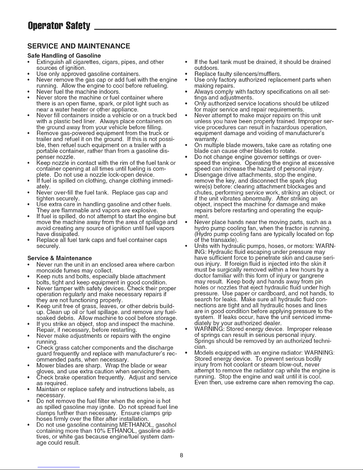
SERVICE AND MAINTENANCE
Safe Handling of Gasoline
Extinguish all cigarettes, cigars, pipes, and other
sources of ignition.
Use only approved gasoline containers.
Never remove the gas cap or add fuel with the engine
running. Allow the engine to cool before refueling.
Never fuel the machine indoors.
Never store the machine or fuel container where
there is an open flame, spark, or pilot light such as
near a water heater or other appliance.
Never fill containers inside a vehicle or on a truck bed
with a plastic bed liner. Always place containers on
the ground away from your vehicle before filling.
Remove gas-powered equipment from the truck or
trailer and refuel it on the ground, if this is not possi-
ble, then refuel such equipment on a trailer with a
portable container, rather than from a gasoline dis-
penser nozzle.
Keep nozzle in contact with the rim of the fuel tank or
container opening at all times until fueling is com-
plete. Do not use a nozzle lock-open device.
if fuel is spilled on clothing, change clothing immedi-
ately.
Never over-fill the fuel tank. Replace gas cap and
tighten securely.
Use extra care in handling gasoline and other fuels.
They are flammable and vapors are explosive.
If fuel is spilled, do not attempt to start the engine but
move the machine away from the area of spillage and
avoid creating any source of ignition until fuel vapors
have dissipated.
Replace all fuel tank caps and fuel container caps
securely.
Service & Maintenance
Never run the unit in an enclosed area where carbon
monoxide fumes may collect.
Keep nuts and bolts, especially blade attachment
bolts, tight and keep equipment in good condition.
Never tamper with safety devices. Check their proper
operation regularly and make necessary repairs if
they are not functioning properly.
Keep unit free of grass, leaves, or other debris build-
up. Clean up oil or fuel spillage, and remove any fuel-
soaked debris. Allow machine to cool before storage.
If you strike an object, stop and inspect the machine.
Repair, if necessary, before restarting.
Never make adjustments or repairs with the engine
running.
Check grass catcher components and the discharge
guard frequently and replace with manufacturer's rec-
ommended parts, when necessary.
Mower blades are sharp. Wrap the blade or wear
gloves, and use extra caution when servicing them.
Check brake operation frequently. Adjust and service
as required.
Maintain or replace safety and instructions labels, as
necessary.
Do not remove the fuel filter when the engine is hot
as spilled gasoline may ignite. Do not spread fuel line
clamps further than necessary. Ensure clamps grip
hoses firmly over the filter after installation.
Do not use gasoline containing METHANOL, gasohol
containing more than 10% ETHANOL, gasoline addi-
tives, or white gas because engine/fuel system dam-
age could result.
If the fuel tank must be drained, it should be drained
outdoors.
Replace faulty silencers/mufflers.
Use only factory authorized replacement parts when
making repairs.
Always comply with factory specifications on all set-
tings and adjustments.
Only authorized service locations should be utilized
for major service and repair requirements.
Never attempt to make major repairs on this unit
unless you have been properly trained. Improper ser-
vice procedures can result in hazardous operation,
equipment damage and voiding of manufacturer's
warranty.
On multiple blade mowers, take care as rotating one
blade can cause other blades to rotate.
Do not change engine governor settings or over-
speed the engine. Operating the engine at excessive
speed can increase the hazard of personal injury.
Disengage drive attachments, stop the engine,
remove the key, and disconnect the spark plug
wire(s) before: clearing attachment blockages and
chutes, performing service work, striking an object, or
if the unit vibrates abnormally. After striking an
object, inspect the machine for damage and make
repairs before restarting and operating the equip-
ment.
Never place hands near the moving parts, such as a
hydro pump cooling fan, when the tractor is running.
(Hydro pump cooling fans are typically located on top
of the transaxle).
Units with hydraulic pumps, hoses, or motors: WARN-
ING: Hydraulic fluid escaping under pressure may
have sufficient force to penetrate skin and cause seri-
ous injury. If foreign fluid is injected into the skin it
must be surgically removed within a few hours by a
doctor familiar with this form of injury or gangrene
may result. Keep body and hands away from pin
holes or nozzles that eject hydraulic fluid under high
pressure. Use paper or cardboard, and not hands, to
search for leaks. Make sure all hydraulic fluid con-
nections are tight and all hydraulic hoses and lines
are in good condition before applying pressure to the
system. If leaks occur, have the unit serviced imme-
diately by your authorized dealer.
WARNING: Stored energy device. Improper release
of springs can result in serious personal injury.
Springs should be removed by an authorized techni-
cian.
• Models equipped with an engine radiator: WARNING:
Stored energy device. To prevent serious bodily
injury from hot coolant or steam blow-out, never
attempt to remove the radiator cap while the engine is
running. Stop the engine and wait until it is cool.
Even then, use extreme care when removing the cap.
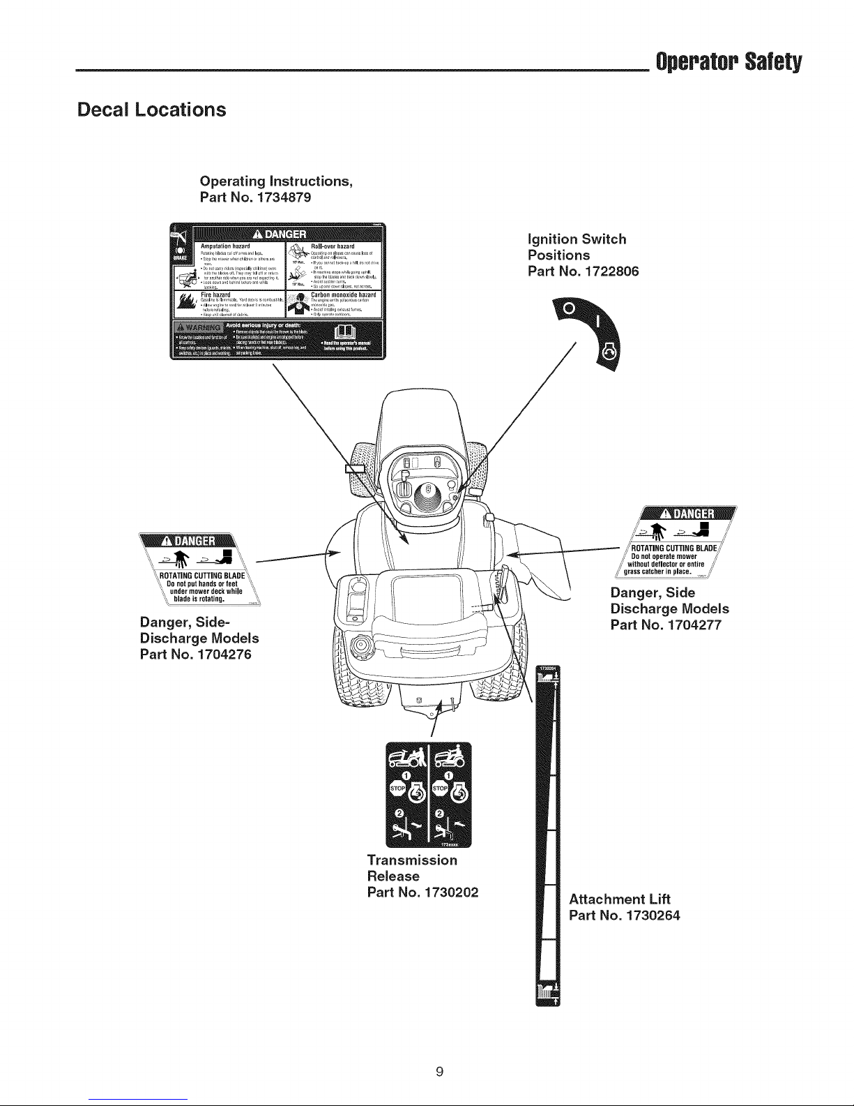
Decal Locations
Operating instructions,
Part No. 1734879
Fire hazard
OperatorSafety
ignition Switch
Positions
Part No. 1722806
",i_ _1_ .:> J "ii!i_,
",',_ROTATING CUTTING BLADE'S,
"_,',_Do not put hands or feet "_,
',',_ under mower deck while "_,
"'7 blade is rotating. ",_,_
Danger, Side-
Discharge Models
Part No. 1704276
Transmission
Release
Part No. 1730202
_, ROTATING CUTTING BLADE,i"
/_; Do not operate mower ,_'
/;' without deflector or entire o,//'
_' grass catcher n p ace ,_'
Danger, Side
Discharge Models
Part No. 1704277
Attachment Lift
Part No. 1730264
g
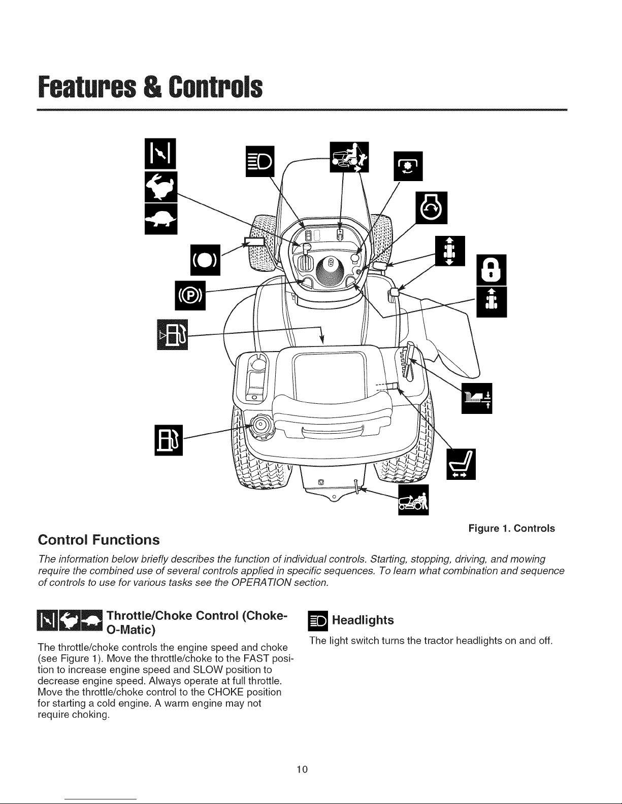
Features& Controls
Control Functions
The information below briefly describes the function of individual controls. Starting, stopping, driving, and mowing
require the combined use of several controls appfied in specific sequences. To learn what combination and sequence
of controls to use for various tasks see the OPERA T!ON section.
_]__ Throttle/Choke Control (Choke-
The throttle/choke controls the engine speed and choke
(see Figure 1). Move the throttle/choke to the FAST posi-
tion to increase engine speed and SLOW position to
decrease engine speed. Always operate at full throttle.
Move the throttle/choke control to the CHOKE position
for starting a cold engine. A warm engine may not
require choking.
O-iVlatic)
Figure 1. Controls
W Headlights
The light switch turns the tractor headlights on and off.
10

Features&Controls
_ Reverse Mowing Option (RMO)
The Reverse Mowing Option allows for mowing (or use
of other PTO driven attachments) while traveling in
reverse. If you choose to mow in reverse, turn the RMO
key after the PTO is engaged. The L.E.D. light will illumi-
nate, and the operator can then mow in reverse. Each
time the PTO is engaged the RMO needs to be reactivat-
ed ifdesired.
O PTO Switch
The PTO (Power Take-Off) switch engages and disen-
gages attachments that use the PTO. To engage the
PTO, pull UP on the switch. Push DOWN to disengage.
Note that the operator must be seated firmly in the trac-
tor seat for the PTO to function.
_"_ Ignition Switch
The ignition switch starts and stops the engine, it has
three positions:
r_OFF Stops the engine and shuts off the
electrical system.
O RUN
[!_ START Cranks the engine for starting.
NOTE: Never leave the ignition switch in the RUN posi-
tion with the engine stopped. This drains the battery.
Allows the engine to run and powers the
electrical system.
H Ground Speed Pedals
The tractor's forward ground speed is controlled by the
forward ground speed control pedal. The tractor's
reverse ground speed is controlled by the reverse
ground speed control pedal.
Depressing either pedal will increase ground speed.
Note that the further down the pedal is depressed, the
faster the tractor will travel.
Mower Height of Cut Adjustment
The mower cutting height adjustment lever controls the
mower cutting height. The mower cutting height can be
set to one of seven positions between 1-1/4" and 4" (3,2
cm and 10,2 cm).
_Seat Adjustment Lever
The seat can be adjusted forward and back. Move the
lever, position the seat as desired, and release the lever
to lock the seat into position.
Transmission Release Valve Lever
The transmission release valve lever deactivates the
transmission so that the tractor can be pushed by hand.
See "Pushing The Tractor By Hand" for operational
information.
r_ Fuel Tank
To remove the cap, turn counterclockwise.
Fuel Level Gauge
Displays the fuel level in the tank.
_ Parking Brake
The parking brake knob is used to lock the parking brake
when the tractor is stopped. Fully depressing the brake
pedal and pulling up on the knob engages the parking
brake.
D Brake Pedal
Depressing the brake pedal applies the tractor brake.
O B Cruise Control
The cruise control is used to lock the ground speed con-
trol in forward. The cruise control has six lock positions.
11
Operation
General Operating Safety
Be sure to read all information in the OPERATOR SAFE-
TY section before attempting to operate this unit.
Become familiar with all of the controls and how to stop
the unit.
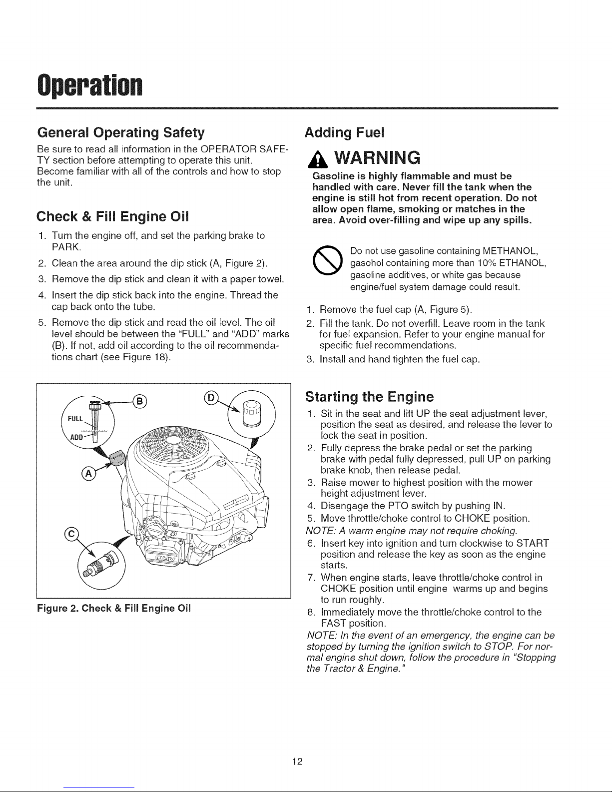
Check & Fill Engine Oil
1. Turn the engine off, and set the parking brake to
PARK.
2. Clean the area around the dip stick (A, Figure 2).
3. Remove the dip stick and clean it with a paper towel.
4. Insert the dip stick back into the engine. Thread the
cap back onto the tube.
5. Remove the dip stick and read the oil level. The oil
level should be between the "FULL" and "ADD" marks
(B). If not, add oil according to the oil recommenda-
tions chart (see Figure 18).
Figure 2. Check & Fill Engine Oil
Adding Fuel
WARNING
Gasoline is highly flammable and must be
handled with care. Never fill the tank when the
engine is still hot from recent operation. Do not
allow open flame, smoking or matches in the
area. Avoid over-filling and wipe up any spills.
Do not use gasoline containing METHANOL,
gasohol containing more than 10% ETHANOL,
gasoline additives, or white gas because
engine/fuel system damage could result.
1. Remove the fuel cap (A, Figure 5).
2. Fill the tank. Do not overfill. Leave room in the tank
for fuel expansion. Refer to your engine manual for
specific fuel recommendations.
3. Install and hand tighten the fuel cap.
Starting the Engine
1. Sit in the seat and lift UP the seat adjustment lever,
position the seat as desired, and release the lever to
lock the seat in position.
2. Fully depress the brake pedal or set the parking
brake with pedal fully depressed, pull UP on parking
brake knob, then release pedal.
3. Raise mower to highest position with the mower
height adjustment lever.
4. Disengage the PTO switch by pushing IN.
5. Move throttle/choke control to CHOKE position.
NOTE: A warm engine may not require choking.
6. Insert key into ignition and turn clockwise to START
position and release the key as soon as the engine
starts.
7. When engine starts, leave throttle/choke control in
CHOKE position until engine warms up and begins
to run roughly.
8. Immediately move the throttle/choke control to the
FAST position.
NOTE: In the event of an emergency, the engine can be
stopped by turning the ignition switch to STOP. For nor-
mal engine shut down, follow the procedure in "Stopping
the Tractor & Engine."
12
Operatm,
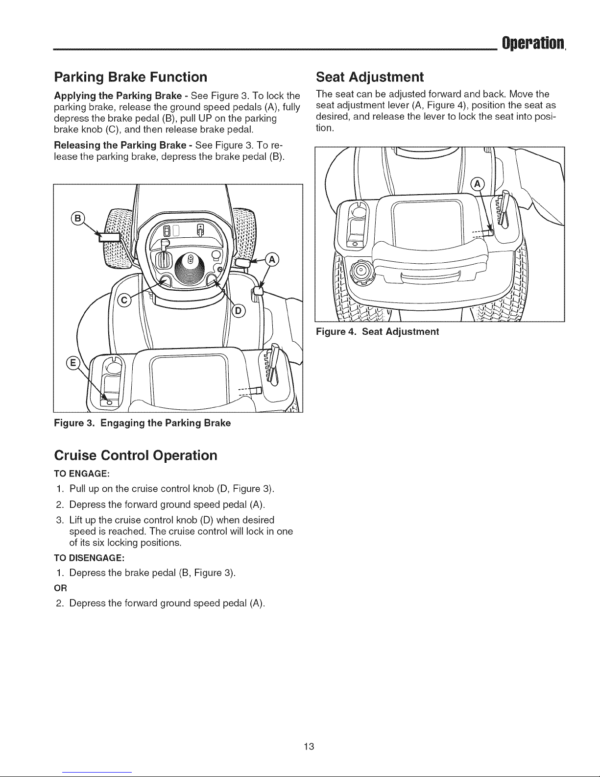
Parking Brake Function
Applying the Parking Brake =See Figure 3. To lock the
parking brake, release the ground speed pedals (A), fully
depress the brake pedal (B), pull UP on the parking
brake knob (C), and then release brake pedal.
Releasing the Parking Brake = See Figure 3. To re-
lease the parking brake, depress the brake pedal (B).
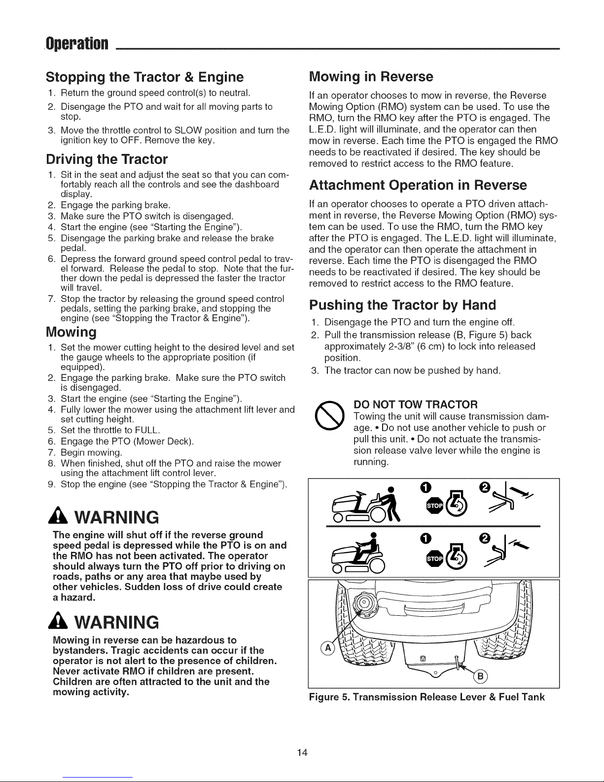
Seat Adjustment
The seat can be adjusted forward and back. Move the
seat adjustment lever (A, Figure 4), position the seat as
desired, and release the lever to lock the seat into posi-
tion.
Figure 4. Seat Adjustment
Figure 3. Engaging the Parking Brake
Cruise Control Operation
TO ENGAGE:
1. Pull up on the cruise control knob (D, Figure 3).
2. Depress the forward ground speed pedal (A).
3. Lift up the cruise control knob (D) when desired
speed is reached. The cruise control will lock in one
of its six lockingpositions.
TO DISENGAGE:
1. Depress the brake pedal (B, Figure 3).
OR
2. Depress the forward ground speed pedal (A).
13
,Operation
Stopping the Tractor & Engine
1. Return the ground speed control(s) to neutral.
2. Disengage the PTO and wait for all moving parts to
stop.
3. Move the throttle control to SLOW position and turn the
ignition key to OFF. Remove the key.
Driving the Tractor
1. Sit in the seat and adjust the seat so that you can com-
fortably reach all the controls and see the dashboard
display.
2. Engage the parking brake.
3. Make sure the PTO switch is disengaged.
4. Start the engine (see "Starting the Engine").
5. Disengage the parking brake and release the brake
pedal.
6. Depress the forward ground speed control pedal to trav-
el forward. Release the pedal to stop. Note that the fur-
ther down the pedal is depressed the faster the tractor
will travel.
7. Stop the tractor by releasing the ground speed control
pedals, setting the parking brake, and stopping the
engine (see "Stopping the Tractor & Engine").
Mowing
1. Set the mower cutting height to the desired level and set
the gauge wheels to the appropriate position (if
equipped).
2. Engage the parking brake. Make sure the PTO switch
is disengaged.
3. Start the engine (see "Starting the Engine").
4. Fully lower the mower using the attachment lift lever and
set cutting height.
5. Set the throttle to FULL.
6. Engage the PTO (Mower Deck).
7. Begin mowing.
8. When finished, shut off the PTO and raise the mower
using the attachment lift control lever.
9. Stop the engine (see "Stopping the Tractor & Engine").
Mowing in Reverse
If an operator chooses to mow in reverse, the Reverse
Mowing Option (RMO) system can be used. To use the
RMO, turn the RMO key after the PTO is engaged. The
L.E.D. light will illuminate, and the operator can then
mow in reverse. Each time the PTO is engaged the RMO
needs to be reactivated if desired. The key should be
removed to restrict access to the RMO feature.
Attachment Operation in Reverse
If an operator chooses to operate a PTO driven attach-
ment in reverse, the Reverse Mowing Option (RMO) sys-
tem can be used. To use the RMO, turn the RMO key
after the PTO is engaged. The L.E.D. light will illuminate,
and the operator can then operate the attachment in
reverse. Each time the PTO is disengaged the RMO
needs to be reactivated if desired. The key should be
removed to restrict access to the RMO feature.
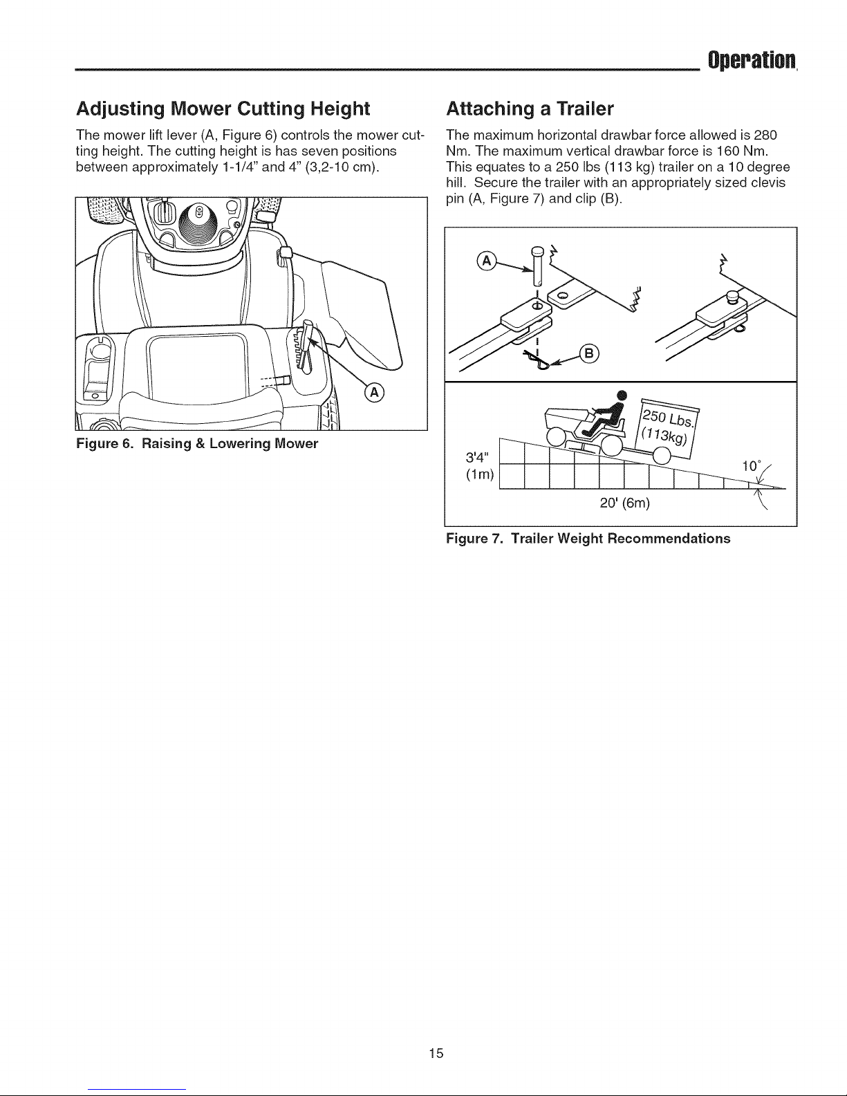
Pushing the Tractor by Hand
1. Disengage the PTO and turn the engine off.
2. Pull the transmission release (B, Figure 5) back
approximately 2-3/8" (6 cm) to lock into released
position.
3. The tractor can now be pushed by hand.
DO NOT TOW TRACTOR
®
Towing the unit will cause transmission dam-
age. • Do not use another vehicle to push or
pull this unit. • Do not actuate the transmis-
sion release valve lever while the engine is
running.
WARNING
The engine will shut off if the reverse ground
speed pedal is depressed while the PTO is on and
the RMO has not been activated. The operator
should always turn the PTO off prior to driving on
roads, paths or any area that maybe used by
other vehicles. Sudden loss of drive could create
a hazard.
WARNING
Mowing in reverse can be hazardous to
bystanders. Tragic accidents can occur if the
operator is not alert to the presence of children.
Never activate RMO if children are present.
Children are often attracted to the unit and the
mowing activity,
O
®
Figure 5. Transmission Release Lever & Fuel Tank
14
Operation,
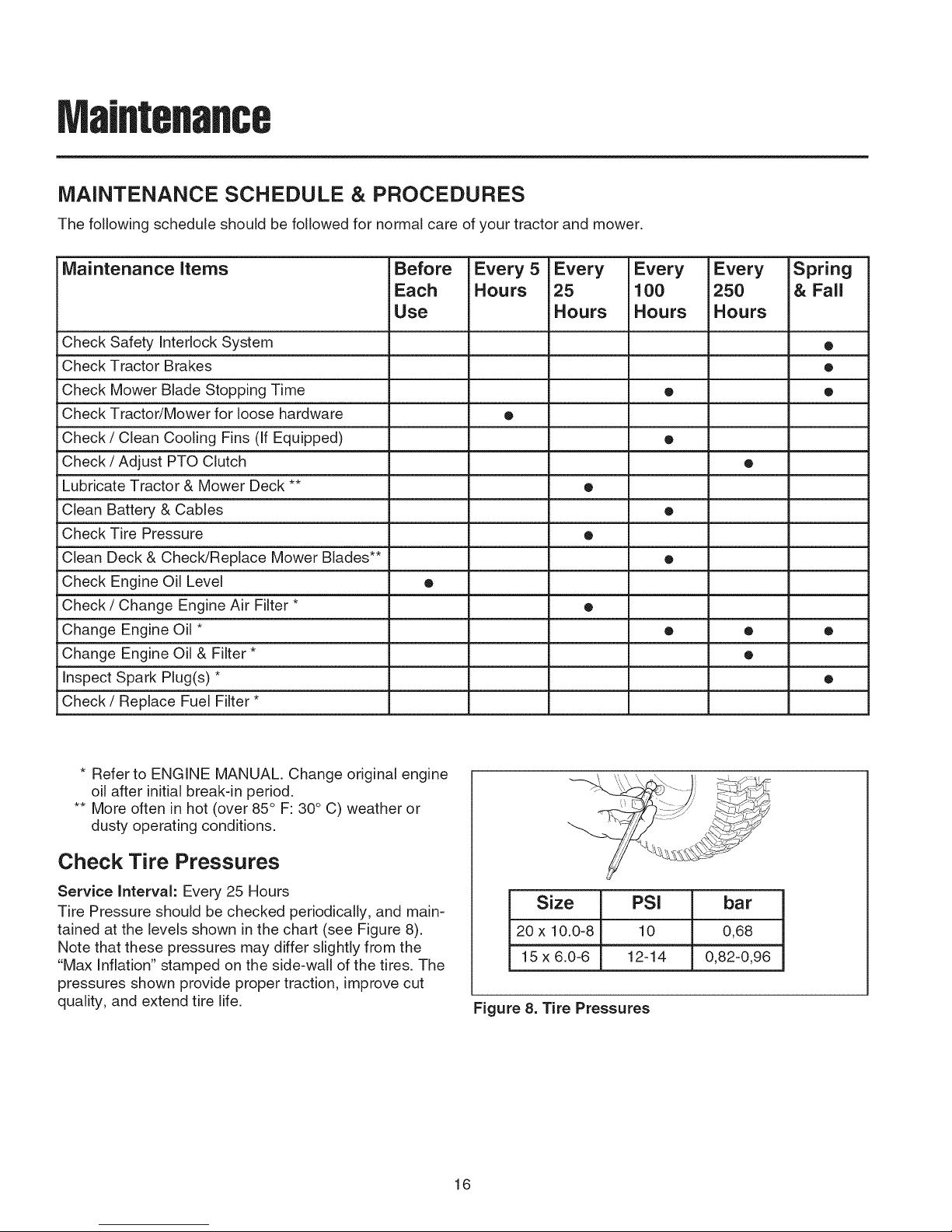
Adjusting Mower Cutting Height
The mower lift lever (A, Figure 6) controls the mower cut-
ring height. The cutting height is has seven positions
between approximately 1-1/4" and 4" (3,2-10 cm).
Figure 6. Raising & Lowering Mower
Attaching a Trailer
The maximum horizontal drawbar force allowed is 280
Nm. The maximum vertical drawbar force is 160 Nm.
This equates to a 250 Ibs (113 kg) trailer on a 10 degree
hill. Secure the trailer with an appropriately sized clevis
pin (A, Figure 7) and clip (B).
®
'4"
(lm)
20' (6m)
10°
Figure 7. Trailer Weight Recommendations
15
Maintenance
MAINTENANCE SCHEDULE & PROCEDURES
The following schedule should be followed for normal care of your tractor and mower,
Maintenance items Before Every 5 Every Every Every Spring
Each Hours 25 100 250 & Fall
Use Hours Hours Hours
Check Safety Interlock System •
Check Tractor Brakes •
Check Mower Blade Stopping Time • •
Check Tractor/Mower for loose hardware •
Check / Clean Cooling Fins (If Equipped) •
Check / Adjust PTO Clutch •
Lubricate Tractor & Mower Deck ** •
Clean Battery & Cables •
Check Tire Pressure •
Clean Deck & Check/Replace Mower Blades** •
Check Engine Oil Level •
Check / Change Engine Air Filter * •
Change Engine Oil * • • •
Change Engine Oil & Filter * •
Inspect Spark Plug(s) * •
Check/Replace Fuel Filter *
* Refer to ENGINE MANUAL. Change original engine
oil after initial break-in period.
** More often in hot (over 85° F: 30° C) weather or
dusty operating conditions.
Check Tire Pressures
Service Interval: Every 25 Hours
Tire Pressure should be checked periodically, and main-
tained at the levels shown in the chart (see Figure 8).
Note that these pressures may differ slightly from the
"Max Inflation" stamped on the side-wall of the tires. The
pressures shown provide proper traction, improve cut
quality, and extend tire life.
Size PSI bar
20 x 10.0-8 10 0,68
15 x 6.0-6 12-14 0,82-0,96
Figure 8. Tire Pressures
16

MaJflteflaflce
Check Safety interlock System
Service interval: Every Fall & Spring
This unit is equipped with safety interlock switches and
other safety devices. These safety systems are present
for your safety: do not attempt to bypass safety switches,
and never tamper with safety devices.
Check the seat switch operation every fall and spring
with the following tests.
Test 1 -- Engine should NOT crank if:
• PTO switch is ON, OR
• Brake pedal is NOT fully depressed (parking brake
OFF),
Test 2 -- Engine SHOULD crank if:
• PTO switch is OFF, AND
• Brake pedal is fully depressed (parking brake ON),
AND
Test 3 -- Engine should SHUT OFF if:
* Operator rises off seat with PTO engaged, OR
* Operator rises off seat with brake pedal NOT fully
depressed (parking brake OFF).
Test 4 -- Blade Brake Check
Mower blades and mower drive belt should come to a
complete stop within five seconds after electric PTO
switch is turned OFF (or operator rises off seat). If
mower drive belt does not stop within five seconds, re
adjust the PTO clutch as described in the MAINTE-
NANCE section or see your dealer.
Test 5 -- Reverse Mow Option (RMO) Check
* Engine should shut off if: PTO is engaged AND RMO
is not activated AND reverse pedal is depressed.
* RMO light should illuminate if: RMO is engaged AND
PTO switch is activated.
NOTE: Once the engine has stopped, the PTO switch
must be turned off after the operator returns to the seat
in order to start the engine,
Check Blade Brake
Service Interval: Every 100 Hours or Fall & Spring
Mower blades and mower drive belt should come to a
complete stop within five seconds after the electric PTO
switch is turned off.
1. With tractor in neutral, PTO disengaged and operator
in seat, start the engine.
2. Look over the left-hand footrest at the mower drive
belt. Engage the PTO and wait several seconds.
Disengage the PTO and check the amount of time it
takes for the mower drive belt to stop.
3. If mower drive belt does not stop within five seconds,
re-adjust the clutch or see your dealer.
Engine Maintenance
Refer to the ENGINE MANUAL for all engine mainte-
nance procedures and recommendations.
WARNING
if the unit does not pass a safety test, do not
operate it. See your authorized dealer. Under no
circumstance should you attempt to defeat the
purpose of the safety interlock system.
17
Maintenance
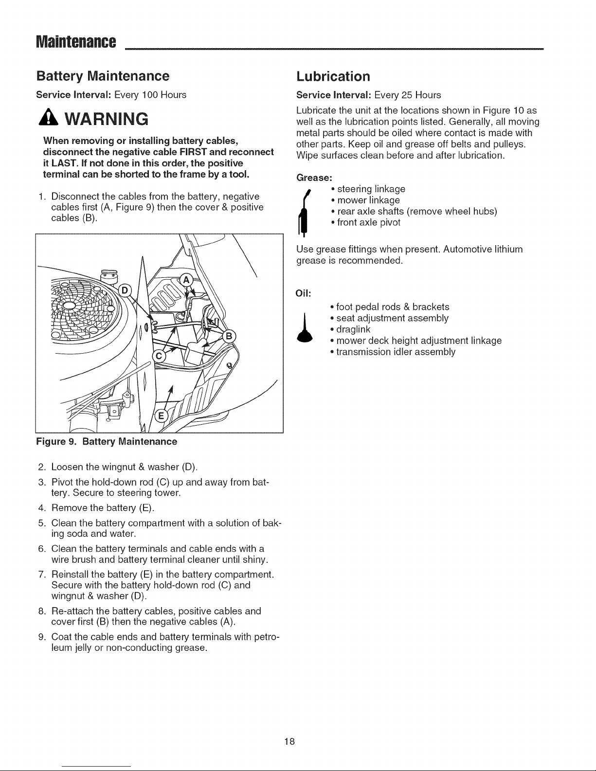
Battery Maintenance
Service interval: Every 100 Hours
WARNING
When removing or installing battery cables,
disconnect the negative cable FIRST and reconnect
it LAST. if not done in this order, the positive
terminal can be shorted to the frame by a tool.
1. Disconnect the cables from the battery, negative
cables first (A, Figure 9) then the cover & positive
cables (B).
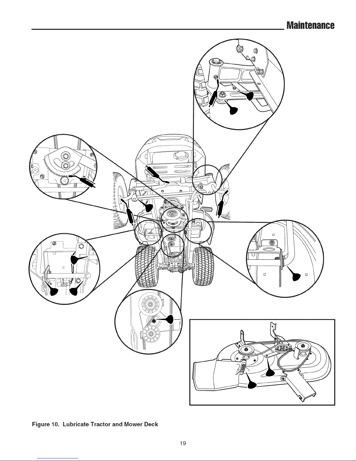
Lubrication
Service interval: Every 25 Hours
Lubricate the unit at the locations shown in Figure 10 as
well as the lubrication points listed. Generally, all moving
metal parts should be oiled where contact is made with
other parts. Keep oil and grease off belts and pulleys.
Wipe surfaces clean before and after lubrication.
Grease:
• mower linkage
• rear axle shafts (remove wheel hubs)
[_ * steering linkage
Use grease fittings when present. Automotive lithium
grease is recommended.
Oil:
• front axle pivot
* foot pedal rods & brackets
* draglink
* seat adjustment assembly
* mower deck height adjustment linkage
* transmission idler assembly
Figure 9. Battery Maintenance
2. Loosen the wingnut & washer (D).
3. Pivot the hold-down rod (C) up and away from bat-
tery. Secure to steering tower.
4. Remove the battery (E).
5. Clean the battery compartment with a solution of bak-
ing soda and water.
6. Clean the battery terminals and cable ends with a
wire brush and battery terminal cleaner until shiny.
7. Reinstall the battery (E) in the battery compartment.
Secure with the battery hold-down rod (C) and
wingnut & washer (D).
8. Re-attach the battery cables, positive cables and
cover first (B) then the negative cables (A).
9. Coat the cable ends and battery terminals with petro-
leum jelly or non-conducting grease.
18
MaJflteflaflce
Figure 10. Lubricate Tractor and Mower Deck
19
MaJflteflaflce
Servicing the Mower Blades
Service interval: Every 100 Hours or As Required
WARNING
For your personal safety, do not handle the sharp
mower blades with bare hands. Careless or
improper handling of blades may result in serious
injury.
WARNING
For your personal safety, blade mounting
capscrews must each be installed with two spring
washers or a he× washer and spring washer, then
securely tightened. Tighten blade mounting nut to
70=80 ft=lbs (95=108 Nm). Tighten blade mounting
capscrew to 45=55 ff-lbs (61=75 Nm).
1. Remove mower deck (see "Mower Deck Removal").
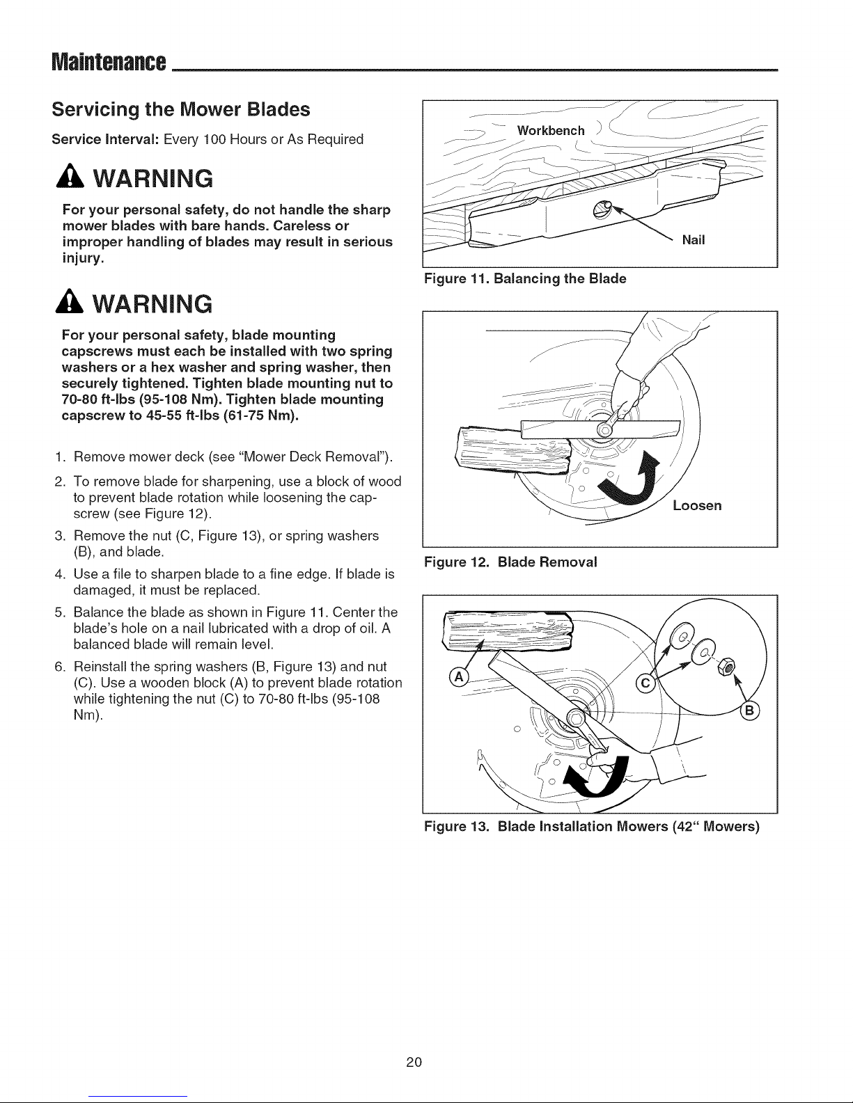
Nail
Figure 11. Balancing the Blade
2. To remove blade for sharpening, use a block of wood
to prevent blade rotation while loosening the cap-
screw (see Figure 12).
3. Remove the nut (C, Figure 13), or spring washers
(B), and blade.
4. Use a file to sharpen blade to a fine edge. If blade is
damaged, it must be replaced.
5. Balance the blade as shown in Figure 11. Center the
blade's hole on a nail lubricated with a drop of oil. A
balanced blade will remain level.
6. Reinstall the spring washers (B, Figure 13) and nut
(C). Use a wooden block (A) to prevent blade rotation
while tightening the nut (C) to 70-80 ft-lbs (95-108
Nm).
Loosen
Figure 12. Blade Removal
Figure 13. Blade Installation Mowers (42" Mowers)
20
Mower Deck Removal & Installation
Service JntervaJ:As Required
WARNING
Engage parking brake, disengage PTO, stop
engine and remove key before attempting to
instalJ or remove the mower.
Removing the Mower Deck
1. Park tractor on a hard, level surface such as a con-
crete floor. Turn off PTO switch and engine, remove
the key and apply parking brake.
2. Place wood blocks under the mower deck. Place the
attachment lift in the lowest position.
3. Move idler arm (A, Figure 15) to relieve belt tension.
Remove belt from PTO pulley (B).
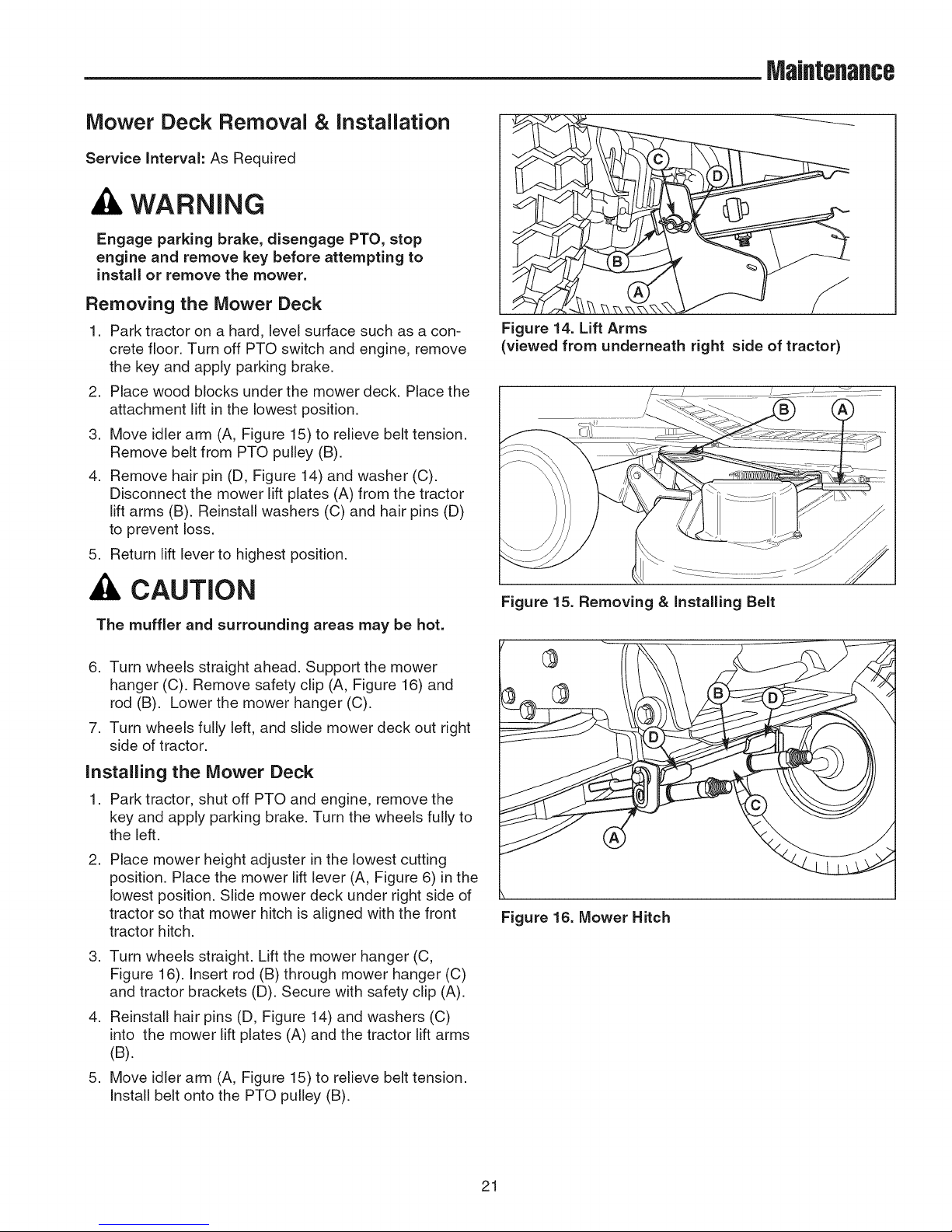
4. Remove hair pin (D, Figure 14) and washer (C).
Disconnect the mower lift plates (A) from the tractor
lift arms (B). Reinstall washers (C) and hair pins (D)
to prevent loss.
5. Return lift lever to highest position.
MaJflteflaflce
Figure 14. Lift Arms
(viewed from underneath right side of tractor)
CAUTION
The muffler and surrounding areas may be hot.
6. Turn wheels straight ahead. Support the mower
hanger (C). Remove safety clip (A, Figure 16) and
rod (B). Lower the mower hanger (C).
7. Turn wheels fully left, and slide mower deck out right
side of tractor.
Installing the Mower Deck
1. Park tractor, shut off PTO and engine, remove the
key and apply parking brake. Turn the wheels fully to
the left.
,
Place mower height adjuster in the lowest cutting
position. Place the mower lift lever (A, Figure 6) in the
lowest position. Slide mower deck under right side of
tractor so that mower hitch is aligned with the front
tractor hitch.
3. Turn wheels straight. Lift the mower hanger (C,
Figure 16). Insert rod (B) through mower hanger (C)
and tractor brackets (D). Secure with safety clip (A).
4. Reinstall hair pins (D, Figure 14) and washers (C)
into the mower lift plates (A) and the tractor lift arms
(B).
5. Move idler arm (A, Figure 15) to relieve belt tension.
Install belt onto the PTO pulley (B).
Figure 15. Removing & Installing Belt
®
®
Figure 16. Mower Hitch
21
Maintenance
Oil Drain Valve Operation
Service interval: As Required
1. Place a suitable container with a 4 quart capacity
under the oil drain valve (C, Figure 2).
2. Loosen or remove the dip stick (A).
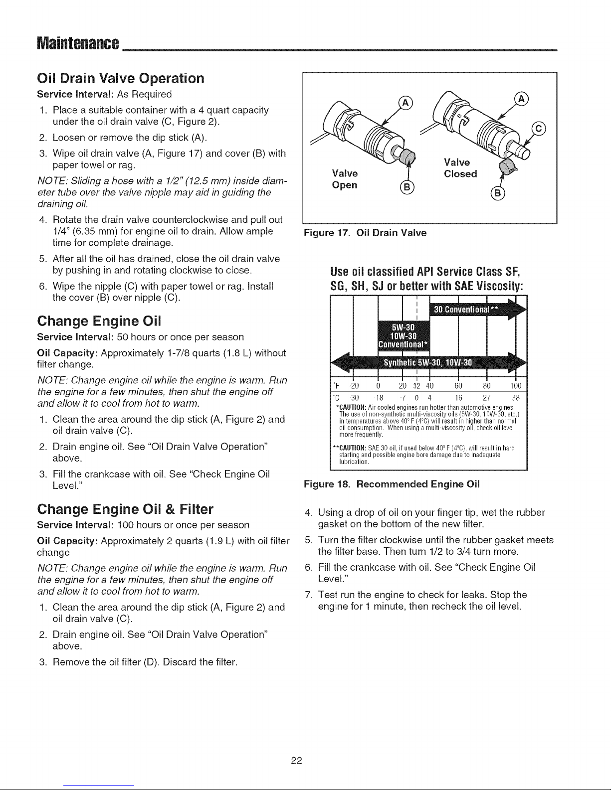
3. Wipe oil drain valve (A, Figure 17) and cover (B) with
paper towel or rag.
NOTE: Sliding a hose with a 1/2" (12.5 mm) inside diam-
eter tube over the valve nipple may aid in guiding the
draining oil.
4. Rotate the drain valve counterclockwise and pull out
1/4" (6.35 ram) for engine oil to drain. Allow ample
time for complete drainage.
5. After all the oil has drained, close the oil drain valve
by pushing in and rotating clockwise to close.
6. Wipe the nipple (C) with paper towel or rag. Install
the cover (B) over nipple (C).
Change Engine Oil
Service Interval: 50 hours or once per season
Oil Capacity: Approximately 1-7/8 quarts (1.8 L) without
filter change.
NOTE: Change engine oil while the engine is warm. Run
the engine for a few minutes, then shut the engine off
and allow it to cool from hot to warm.
1. Clean the area around the dip stick (A, Figure 2) and
oil drain valve (C).
2. Drain engine oil. See "Oil Drain Valve Operation"
above.
3. Fill the crankcase with oil. See "Check Engine Oil
Level."
Figure 17. Oil Drain Valve
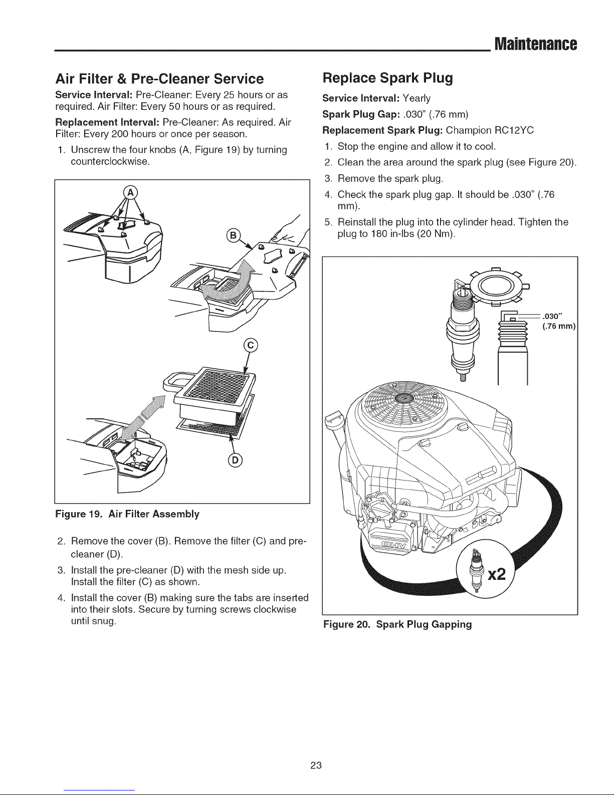
Useoil classifiedAPIService ClassSF,
SG,SH,SJ orbetterwith SAEViscosity:
II "
°F -20 0 20 32 40 60 80 100
°C -30 -18 -7 0 4 16 27 38
*CAUTION:Air cooled engines run hotter than automotive engines.
The use of non-synthetic multi-viscosity oils (5W-30, 10W-30, etc.)
in temperatures above 400F(4°C)will result in higher than normal
oil consumption. When using a multi-viscosity oil, check oil level
more frequently.
**CAUTION: SAE30 oil, if usedbelow 400F (4°C), will result in hard
starting andpossible engine bore damagedue to inadequate
lubrication.
Figure 18. Recommended Engine Oil
I I I! ! ,
Change Engine Oil & Filter 4.
Service Interval: 100 hours or once per season
Oil Capacity: Approximately 2 quarts (1.9 L) with oil filter 5.
change
NOTE: Change engine oil while the engine is warm. Run 6.
the engine for a few minutes, then shut the engine off
and allow it to cool from hot to warm. 7.
1. Clean the area around the dip stick (A, Figure 2) and
oil drain valve (C).
2. Drain engine oil. See "Oil Drain Valve Operation"
above.
3. Remove the oil filter (D). Discard the filter.
Using a drop of oil on your finger tip, wet the rubber
gasket on the bottom of the new filter.
Turn the filter clockwise until the rubber gasket meets
the filter base. Then turn 1/2 to 3/4 turn more.
Fill the crankcase with oil. See "Check Engine Oil
Level."
Test run the engine to check for leaks. Stop the
engine for 1 minute, then recheck the oil level.
22
Maintenance
Air Filter & Pre-Cleaner Service
Service Interval: Pre-Cleaner: Every 25 hours or as
required. Air Filter: Every 50 hours or as required.
Replacement Interval: Pre-Cleaner: As required. Air
Filter: Every 200 hours or once per season.
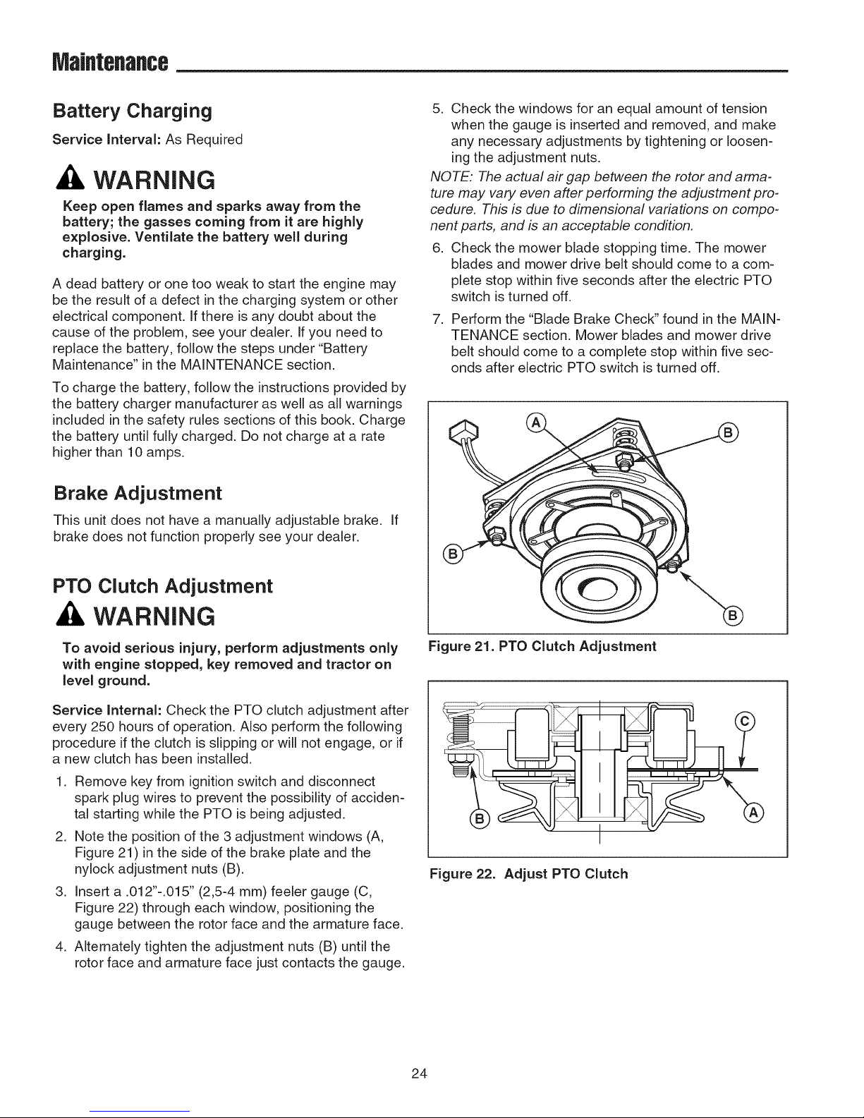
1. Unscrew the four knobs (A, Figure 19) by turning
counterclockwise.
©
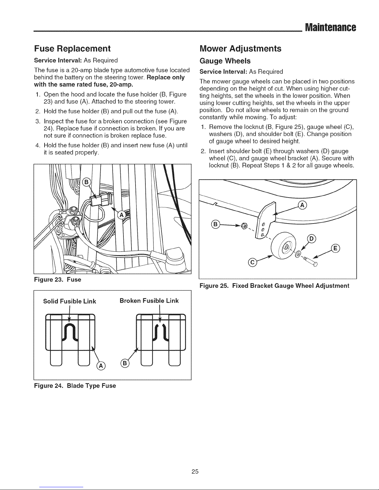
Replace Spark Plug
Service Interval: Yearly
Spark Plug Gap: .030" (.76 mm)
Replacement Spark Plug: Champion RC12YC
1. Stop the engine and allow it to cool.
2. Clean the area around the spark plug (see Figure 20).
3. Remove the spark plug.
4. Check the spark plug gap. It should be .030" (.76
mm).
5. Reinstall the plug into the cylinder head. Tighten the
plug to 180 in-lbs (20 Nm).
_ .030"
I _ _ ( 76 rnrn)
Figure 19. Air Filter Assembly
2. Remove the cover (B). Remove the filter (C) and pre-
cleaner (D).
3. Install the pre-cleaner (D) with the mesh side up.
Install the filter (C) as shown.
4. Install the cover (B) making sure the tabs are inserted
into their slots. Secure by turning screws clockwise
until snug.
Figure 20. Spark Plug Gapping
23
Maintenance
Battery Charging
Service interval: As Required
WARNING
Keep open flames and sparks away from the
battery; the gasses coming from it are highly
explosive. Ventilate the battery well during
charging.
A dead battery or one too weak to start the engine may
be the result of a defect in the charging system or other
electrical component. If there is any doubt about the
cause of the problem, see your dealer. Ifyou need to
replace the battery, follow the steps under "Battery
Maintenance" in the MAINTENANCE section.
To charge the battery, follow the instructions provided by
the battery charger manufacturer as well as all warnings
included in the safety rules sections of this book. Charge
the battery until fully charged. Do not charge at a rate
higher than 10 amps.
Brake Adjustment
5. Check the windows for an equal amount of tension
when the gauge is inserted and removed, and make
any necessary adjustments by tightening or loosen-
ing the adjustment nuts.
NOTE: The actual air gap between the rotor and arma-
ture may vary even after performing the adjustment pro-
cedure. This is due to dimensional variations on compo-
nent parts, and is an acceptable condition.
6. Check the mower blade stopping time. The mower
blades and mower drive belt should come to a com-
plete stop within five seconds after the electric PTO
switch is turned off.
, Perform the "Blade Brake Check" found in the MAIN-
TENANCE section. Mower blades and mower drive
belt should come to a complete stop within five sec-
onds after electric PTO switch is turned off.
This unit does not have a manually adjustable brake. If
brake does not function properly see your dealer.
PTO Clutch Adjustment
WARNING
To avoid serious injury, perform adjustments only
with engine stopped, key removed and tractor on
level ground.
Service Internal: Check the PTO clutch adjustment after
every 250 hours of operation. Also perform the following
procedure if the clutch is slipping or will not engage, or if
a new clutch has been installed.
1. Remove key from ignition switch and disconnect
spark plug wires to prevent the possibility of acciden-
tal starting while the PTO is being adjusted.
2. Note the position of the 3 adjustment windows (A,
Figure 21) in the side of the brake plate and the
nylock adjustment nuts (B).
3. Insert a .012"-.015" (2,5-4 mm) feeler gauge (C,
Figure 22) through each window, positioning the
gauge between the rotor face and the armature face.
4. Alternately tighten the adjustment nuts (B) until the
rotor face and armature face just contacts the gauge.
Figure 21. PTO Clutch Adjustment
I
Figure 22. Adjust PTO Clutch
24
MaJflteflaflce
Fuse Replacement
Service Interval: As Required
The fuse is a 20-amp blade type automotive fuse located
behind the battery on the steering tower. Replace only
with the same rated fuse, 20=amp.
1. Open the hood and locate the fuse holder (B, Figure
23) and fuse (A). Attached to the steering tower.
2. Hold the fuse holder (B) and pull out the fuse (A).
3. Inspect the fuse for a broken connection (see Figure
24). Replace fuse if connection is broken. If you are
not sure if connection is broken replace fuse.
4. Hold the fuse holder (B) and insert new fuse (A) until
it is seated properly.
Mower Adjustments
Gauge Wheels
Service Interval: As Required
The mower gauge wheels can be placed in two positions
depending on the height of cut. When using higher cut-
ting heights, set the wheels in the lower position. When
using lower cutting heights, set the wheels in the upper
position. Do not allow wheels to remain on the ground
constantly while mowing. To adjust:
1. Remove the Iocknut (B, Figure 25), gauge wheel (C),
washers (D), and shoulder bolt (E). Change position
of gauge wheel to desired height.
2. Insert shoulder bolt (E) through washers (D) gauge
wheel (C), and gauge wheel bracket (A). Secure with
Iocknut (B). Repeat Steps 1 & 2 for all gauge wheels.
Figure 23. Fuse
Solid Fusible Link
Figure 24. Blade Type Fuse
Figure 25. Fixed Bracket Gauge Wheel Adjustment
Broken Fusible Link
======_=,%
--j
25
MaJflteflaflce
WARNING
Before checking mower, shut off PTO and engine,
remove the key, and allow all moving parts to
stop.
Leveling The Mower
Service interval: As Required
If the cut is uneven, the mower may need leveling.
Unequal or improper tire pressure may also cause an
uneven cut. Make sure tire pressure is correct as speci-
fied in "Check Tire Pressures."
SIDE-TO=SIDE LEVELING
1. With the mower installed, place the tractor on a
smooth, level surface such as a concrete floor. Turn
the front wheels straight forward.
2. Check for bent blades and replace if necessary.
3. Place the mower in mid-cut position. Arrange the
outside mower blades so that they are pointing from
side-to-side.
4. Measure the distance between the outside tips of
each blade and the ground. If there is more than 1/8"
(3 mm) difference between the measurements on
each side, proceed to Step 5. If the difference is 1/8"
(3 mm) or less, proceed to Step 6.
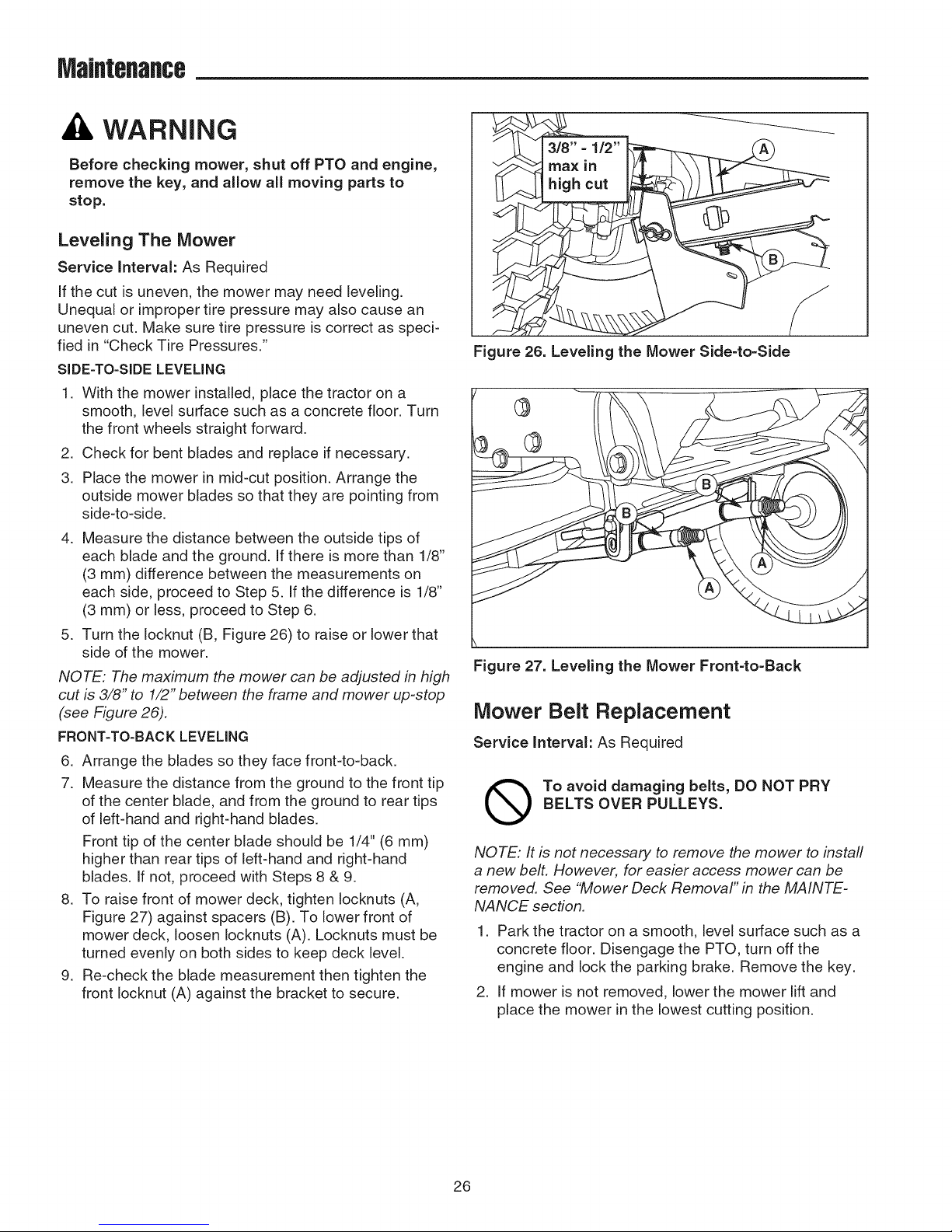
5. Turn the Iocknut (B, Figure 26) to raise or lower that
side of the mower.
NOTE: The maximum the mower can be adjusted in high
cut is 3/8" to 1/2" between the frame and mower up-stop
(see Figure 26).
FRONT=TO=BACKLEVELING
6. Arrange the blades so they face front-to-back.
7. Measure the distance from the ground to the front tip
of the center blade, and from the ground to rear tips
of left-hand and right-hand blades.
Front tip of the center blade should be 1/4" (6 mm)
higher than rear tips of left-hand and right-hand
blades. If not, proceed with Steps 8 & 9.
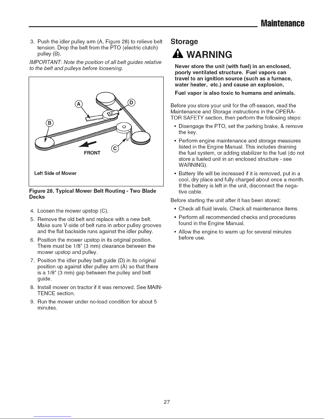
8. To raise front of mower deck, tighten Iocknuts (A,
Figure 27) against spacers (B). To lower front of
mower deck, loosen Iocknuts (A). Locknuts must be
turned evenly on both sides to keep deck level.
9. Re-check the blade measurement then tighten the
front Iocknut (A) against the bracket to secure.
Figure 26. Leveling the Mower Side=to=Side
Figure 27. Leveling the Mower Front-to=Back
Mower Belt Replacement
Service Interval: As Required
Q o avoid damaging belts, DO NOT PRY
NOTE: It is not necessary to remove the mower to instafl
a new belt. However, for easier access mower can be
removed. See "Mower Deck Removal" in the MAINTE-
NANCE section.
1. Park the tractor on a smooth, level surface such as a
2. If mower is not removed, lower the mower lift and
BELTS OVER PULLEYS.
concrete floor. Disengage the PTO, turn off the
engine and lock the parking brake. Remove the key.
place the mower in the lowest cutting position.
26
MaJflteflaflce
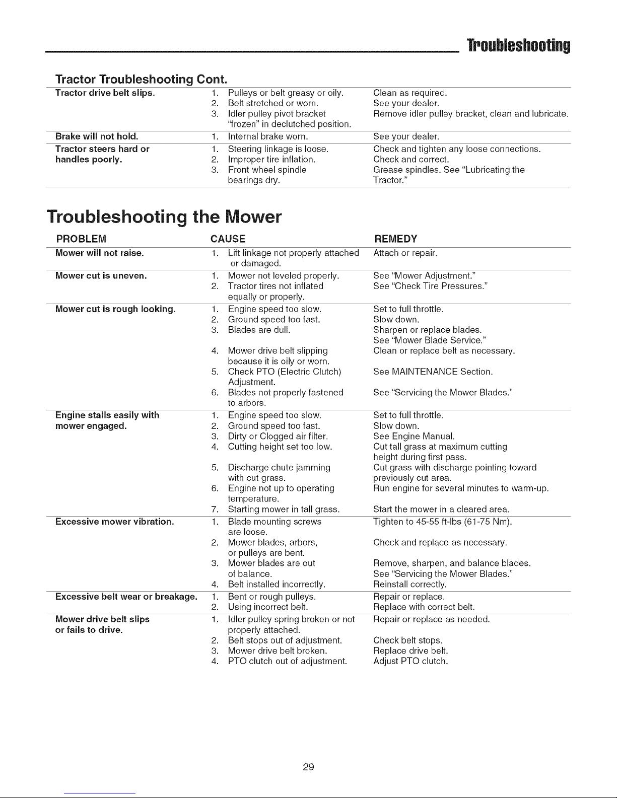
3. Push the idler pulley arm (A, Figure 28) to relieve belt
tension. Drop the belt from the PTO (electric clutch)
pulley (B).
IMPORTANT: Note the position of all belt guides relative
to the belt and pulleys before loosening,
Left Side of Mower
Figure 28. Typical Mower Belt Routing =Two Blade
Decks
4. Loosen the mower upstop (C).
5. Remove the old belt and replace with a new belt.
Make sure V-side of belt runs in arbor pulley grooves
and the fiat backside runs against the idler pulley.
6. Position the mower upstop in its original position.
There must be 1/8" (3 mm) clearance between the
mower upstop and pulley.
7. Position the idler pulley belt guide (D) in its original
position up against idler pulley arm (A) so that there
is a 1/8" (3 mm) gap between the pulley and belt
guide.
,
Install mower on tractor if it was removed. See MAIN-
TENCE section.
9.
Run the mower under no-load condition for about 5
minutes.
Storage
WARNING
Never store the unit (with fuel) in an enclosed,
poorly ventilated structure. Fuel vapors can
travel to an ignition source (such as a furnace,
water heater, etc.) and cause an explosion.
Fuel vapor is also toxic to humans and animals.
Before you store your unit for the off-season, read the
Maintenance and Storage instructions in the OPERA-
TOR SAFETY section, then perform the following steps:
* Disengage the PTO, set the parking brake, & remove
the key.
Perform engine maintenance and storage measures
listed in the Engine Manual. This includes draining
the fuel system, or adding stabilizer to the fuel (do not
store a fueled unit in an enclosed structure - see
WARNING).
* Battery life will be increased if it is removed, put in a
cool, dry place and fully charged about once a month.
If the battery is left in the unit, disconnect the nega-
tive cable.
Before starting the unit after it has been stored:
Check all fluid levels. Check all maintenance items.
Perform all recommended checks and procedures
found in the Engine Manual.
Allow the engine to warm up for several minutes
before use.
27

Troubleshootiflg
Troubleshooting
While normal care and regular maintenance will extend
the life of your equipment, prolonged or constant use
may eventually require that service be performed to
allow it to continue operating properly.
The troubleshooting guide below lists the most common
problems, their causes, and remedies.
See the information on the following pages for instruc-
tions on how to perform most of these minor adjustments
and service repairs yourself. If you prefer, all of these
procedures can be performed for you by your local
authorized dealer.
Troubleshooting the Tractor
PROBLEM
Engine will not turnover or start.
Engine starts hard or runs poorly. 1.
Engine knocks. 1.
Excessive oil consumption. 1.
Engine exhaust is black. 1.
Engine runs, but tractor will 1.
not drive.
CAUSE
1. Brake pedal not depressed.
2. PTO (electric clutch) switch
in ON position.
3. Cruise control engaged.
4. Out of fuel.
5. Engine flooded.
6. Fuse Blown.
7. Battery terminals require
cleaning.
8. Battery discharged or dead.
9. Wiring loose or broken.
10.
Solenoid or starter motor faulty.
11.
Safety interlock switch faulty
12.
Spark plug(s) faulty, fouled
or incorrectly gapped.
13.
Water in fuel.
14.
Gas is old or stale.
Fuel mixture too rich.
2.
Spark plug(s) faulty, fouled, or
incorrectly gapped.
Low oil level.
2.
Using wrong grade oil.
Engine running too hot.
2.
Using wrong weight oil.
3.
Too much oil in crankcase.
Dirty air filter.
2.
Choke closed.
Ground speed control pedals
not depressed.
2.
Transmission release lever
in "push" position.
3.
Drive belt is broken.
4.
Drive belt slips.
5.
Parking brake is engaged.
WARNING
To avoid serious injury, perform maintenance on
the tractor or mower only when the engine is
stopped and the parking brake engaged.
Always remove the ignition key, disconnect the
spark plug wire and fasten it away from the plug
before beginning the maintenance, to prevent
accidental starting of the engine.
REMEDY
Fully depress brake pedal.
Place in OFF position.
Move knob to Neutral/Off position.
If engine is hot, allow it to cool, then refill
the fuel tank.
Disengage choke.
Replace fuse.
See "Battery Maintenance".
Recharge or replace.
Visually check wiring & replace broken or
frayed wires. Tighten loose connections.
See your dealer.
See your dealer.
Clean and gap or replace.
See ENGINE MANUAL.
Drain fuel & refill with fresh fuel. Replace fuel filter.
Drain fuel & refill with fresh fuel. Replace fuel filter.
Clean air filter. Check choke adjustment
Clean and gap or replace.
See engine manual.
Check/add oil as required.
See engine manual.
Clean engine fins, blower screen and
air cleaner. Clean radiator screen.
See engine manual.
Drain excess oil.
Replace air filter. See Engine Manual.
Open choke.
Depress pedals.
Move into drive position.
See your dealer.
See cause and remedy below.
Disengage parking brake.
28
TrouhJeshootJflg
Tractor Troubleshooting Cont.
Tractor drive belt slips. 1. Pulleys or belt greasy or oily. Clean as required.
2. Belt stretched or worn. See your dealer.
3. Idler pulley pivot bracket Remove idler pulley bracket, clean and lubricate.
'_rozen" in declutched position.
Brake will not hold. 1. Internal brake worn. See your dealer.
Tractor steers hard or 1. Steering linkage is loose. Check and tighten any loose connections.
handles poorly. 2. Improper tire inflation. Check and correct.
3. Front wheel spindle Grease spindles. See "Lubricating the
bearings dry. Tractor."
Troubleshooting the Mower
PROBLEM CAUSE REMEDY
Mower will not raise. 1. Lift linkage not properly attached Attach or repair.
or damaged.
Mower cut is uneven. 1. Mower not leveled properly. See "Mower Adjustment."
Mower cut is rough looking. 1. Engine speed too slow. Set to full throttle.
Engine stalls easily with
mower engaged.
Excessive mower vibration.
Excessive belt wear or breakage.
Mower drive belt slips
or fails to drive.
2. Tractor tires not inflated See "Check Tire Pressures."
equally or properly.
2. Ground speed too fast. Slow down.
3. Blades are dull. Sharpen or replace blades.
4. Mower drive belt slipping
because it is oily or worn.
5. Check PTO (Electric Clutch)
Adjustment.
6. Blades not properly fastened
to arbors.
1. Engine speed too slow.
2. Ground speed too fast.
3. Dirty or Clogged air filter.
4. Cutting height set too low.
5. Discharge chute jamming
with cut grass.
6. Engine not up to operating
temperature.
7. Starting mower in tall grass.
1. Blade mounting screws
are loose.
2. Mower blades, arbors,
or pulleys are bent.
3. Mower blades are out
of balance.
4. Belt installed incorrectly.
1. Bent or rough pulleys.
2. Using incorrect belt.
1. Idler pulley spring broken or not
properly attached.
2. Belt stops out of adjustment.
3. Mower drive belt broken.
4. PTO clutch out of adjustment.
See "Mower Blade Service."
Clean or replace belt as necessary.
See MAINTENANCE Section.
See "Servicing the Mower Blades."
Set to full throttle.
Slow down.
See Engine Manual.
Cut tall grass at maximum cutting
height during first pass.
Cut grass with discharge pointing toward
previously cut area.
Run engine for several minutes to warm-up.
Start the mower in a cleared area.
Tighten to 45-55 ft-lbs (61-75 Nm).
Check and replace as necessary.
Remove, sharpen, and balance blades.
See "Servicing the Mower Blades."
Reinstall correctly.
Repair or replace.
Replace with correct belt.
Repair or replace as needed.
Check belt stops.
Replace drive belt.
Adjust PTO clutch.
29
ENGINE:
TRANSMISSION:
K46
23 HP* Briggs & Stratton
Make Briggs & Stratton
Model Extended Life Series TM (ELS)
Horsepower 23 @ 3600 rpm
Displacement 44 cu in. (725 cc)
Electrical System 12 Volt, 9 amp. Alternator, Battery: 230 CCA
Oil Capacity 64 oz (1,9 L) with filter
CHASSIS:
Fuel Tank Cap.
Rear Wheels
Front Wheels
NOTE: Specifications are correct at time of printing and are subject to change without notice.
* The gross power rating for individual gas engine models is labeled in accordance with SAE (Society of Automotive
Engineers) code J1940 (Small Engine Power & Torque Rating Procedure), and rating performance has been
obtained and corrected in accordance with SAE J1995 (Revision 2002-05). Torque values are derived at 3060 RPM;
horsepower values are derived at 3600 RPM. Actual gross engine power will be lower and is affected by, among
other things, ambient operating conditions and engine-to-engine variability. Given both the wide array of products on
which engines are placed and the variety of environmental issues applicable to operating the equipment, the gas
engine will not develop the rated gross power when used in a given piece of power equipment (actual "on-site" or net
power). This difference is due to a variety of factors including, but not limited to, accessories (air cleaner, exhaust,
charging, cooling, carburetor, fuel pump, etc.), application limitations, ambient operating conditions (temperature,
humidity, altitude), and engine-to-engine variability. Due to manufacturing and capacity limitations, Briggs & Stratton
may substitute an engine of higher rated power for this Series engine.
Capacity: 3.5 Gallons (13,2 L)
Tire Size: 20x 10.0-8
Inflation Pressure: 10-12 psi (,68 bar)
Tire Size: 15x 6.0-6
Inflation Pressure: 12-15 psi (0,82-0,96 bar)
Type
Hydraulic Fluid
Speeds
@ 3400 rpm
Continuous Torque
Output
Drawbar Rating
Maximum Weight
on Axle
Hydrostatic Tuff Torq K46
lOw 30 Premium Engine Oil
Forward: 0-5.5 MPH (9,0 kin/h)
Reverse: 0-3.0 MPH (4,6 kin/h)
170 ft-lbs (230,5 Nm)
227 Ibs (103 kg)
675 Ibs (306 kg)
DIMENSIONS:
23hp Tractor
w/42" Mower Deck:
Overall Length 71" (180 cm)
Overall Width 48" (122 cm)
Height 44" (112 cm)
Weight 532 Ibs (242 kg)
Maintenance Items
Many convenient and helpful service and maintenance
items are available from you authorized dealer. Some of
these items include:
Engine Oil
Touch-Up Paint
Grease Gun Kit
8 oz Grease Tube
Tire Sealant
Degrimer/Degreaser
Gas Stabilizer
Replacement Parts
Replacement parts are available from your authorized
dealer. Always use genuine Snapper Service Parts.
Technical Manuals
Additional copies of this manual are available, as well as
fully illustrated parts lists. Technical manuals can be
downloaded from www.snapper.com.
3O

The California Air Resources Board, U.S. EPA, and Briggs & Stratton (B&S) are pleased
to explain the emissions control system warranty on your Model Year 2008 and later
engine/equipment. In California, new small off-road engines must be designed, built, and
equipped to meet the State's stringent anti-smog standards. B&S must warrant the
emissions control system on your engine/equipment for the periods of time listed below
provided there has been no abuse, neglect, or improper maintenance of your small
off-road engine.
Your emissions control system may include parts such as the carburetor or fuel injection
system, fuel tank, ignition system, and catalytic converter. Also included may be hoses,
belts, connectors, sensors, and other emissions-related assemblies.
Where a warrantable condition exists, B&S will repair your engine/equipment at no cost
to you including diagnosis, parts, and labor.
Manufacturer's Warranty Coverage:
Small off-road engines are warranted for two years. If any emissions-related part on your
engine/equipment is defective, the part will be repaired or replaced by B&S.
The following are specific provisions relative to your Emissions Control Warranty Coverage. It is in addition to the B&S engine warranty for non-regulated engines found in the
Operator's Manual.
1. Warranted Emissions Parts
Coverage under this warranty extends only to the parts listed below (the emissions
control systems parts) to the extent these parts were present on the engine
purchased.
a. Fuel Metering System
Cold start enrichment system (soft choke)
Carburetor and internal parts
Fuel pump
Fuel line, fuel line fittings, clamps
Fuel tank, cap and tether
Carbon canister
b. Air Induction System
Air cleaner
Intake manifold
Purge and vent line
c. Ignition System
Spark plug(s)
Magneto ignition system
d. Catalyst System
Catalytic converter
Exhaust manifold
Air injection system or pulse valve
e. Miscellaneous Items Used in Above Systems
Vacuum, temperature, position, time sensitive valves and switches
2. Length of Coverage
Connectors and assemblies
For a period of two years from date of original purchase, B&S warrants to the original
purchaser and each subsequent purchaser that the engine is designed, built, and
equipped so as to conform with all applicable regulations adopted by the Air
Resources Board; that it is free from defects in material and workmanship that could
cause the failure of a warranted part; and that it is identical in all material respects to
the engine described in the manufacturer's application for certification. The warranty
period begins on the date the engine is originally purchased.
Owner's Warranty Responsibilities:
As the small engine/equipment owner, you are responsible for the performance of
the required maintenance listed in your owner's manual. B&S recommends that you
retain all receipts covering maintenance on your engine/equipment, but B&S cannot
deny warranty solely for the lack of receipts or your failure to ensure the performance
of all scheduled maintenance.
As the engine/equipment owner, you should however be aware that B&S may deny
you warranty coverage if your engine/equipment or a part has failed due to abuse,
neglect, improper maintenance, or unapproved modifications.
You are responsible for presenting your engine/equipment to a B&S distribution
center, servicing dealer, or other equivalent entity, as applicable, as soon as a
problem exists. The warranty repairs should be completed in a reasonable amount of
time, not to exceed 30 days. If you have any questions regarding your warranty
rights and responsibilities, you should contact B&S at (414) 259-5262.
The warranty on emissions-related parts is as follows:
Any warranted part that is not scheduled for replacement as required
maintenance in the owner's manual supplied, is warranted for the warranty
period stated above. If any such part fails during the period of warranty
coverage, the part will be repaired or replaced by B&S at no charge to the
owner. Any such part repaired or replaced under the warranty will be warranted
for the remaining warranty period.
Any warranted part that is scheduled only for regular inspection in the owner's
manual supplied, is warranted for the warranty period stated above. Any such
part repaired or replaced under warranty will be warranted for the remaining
warranty period.
Any warranted part that is scheduled for replacement as required maintenance
in the owner's manual supplied, is warranted for the period of time prior to the
first scheduled replacement point for that part. If the part fails prior to the first
scheduled replacement, the part will be repaired or replaced by B&S at no
charge to the owner. Any such part repaired or replaced under warranty will be
warranted for the remainder of the period prior to the first scheduled
replacement point for the part.
Add on or modified parts that are not exempted by the Air Resources Board
may not be used. The use of any non exempted add on or modified parts by the
owner will be grounds for disallowing a warranty claim. The manufacturer will
not be liable to warrant failures of warranted parts caused by the use of a non
exempted add on or modified part.
Consequential Coverage
Coverage shall extend to the failure of any engine components caused by the
failure of any warranted emissions parts.
Claims and Coverage Exclusions
Warranty claims shall be filed according to the provisions of the B&S engine
warranty policy. Warranty coverage does not apply to failures of emissions parts
that are not original equipment B&S parts or to parts that fail due to abuse, neglect,
or improper maintenance as set forth in the B&S engine warranty policy. B&S is not
liable for warranty coverage of failures of emissions parts caused by the use of
add-on or modified parts.
Engines that are certified to meet the California Air Resources Board (CARB) Emissions
Standard must display information regarding the Emissions Durability Period and the Air
Index. Briggs & Stratton makes this information available to the consumer on our
emissions labels. The engine emissions label will indicate certification information.
The Emissions Durability Period describes the number of hours of actual running time
for which the engine is certified to be emissions compliant, assuming proper
maintenance in accordance with the Operating & Maintenance Instructions. The
following categories are used:
Moderate:
Engine is certified to be emissions compliant for 125 hours of actual engine running time.
Intermediate:
Engine is certified to be emissions compliant for 250 hours of actual engine running time.
Extended:
Engine is certified to be emissions compliant for 500 hours of actual engine running time.
For example, a typical walk-behind lawn mower is used 20 to 25 hours per year.
Therefore, the Emissions Durability Period of an engine with an intermediate rating
would equate to 10 to 12 years.
Briggs & Stratton engines are certified to meet the United States Environmental
Protection Agency (USEPA) Phase 2 emissions standards. For Phase 2 certified
engines, the Emissions Compliance Period referred to on the Emissions Compliance
label indicates the number of operating hours for which the engine has been shown to
meet Federal emissions requirements.
For engines less than 225 cc displacement.
Category C = 125 hours, Category B = 250 hours, Category A = 500 hours
For engines of 225 cc or more displacement.
Category C = 250 hours, Category B = 500 hours, Category A = 1000 hours
31

Briggs & Stratton Power Products Group, LLC.
Copyright © 2009 Briggs & Stratton Corporation
Milwaukee, WI USA. All Rights Reserved
www. BRIGGSandSTRATTON.com
www.snapper.com
32

Modelo No. 130.288370
Serie LT-125 Hidrotractores
Ref. fab.
2690826
Description
LT23420, 23,0 HP y platforma del cortacesped
107 cm (42 pulg.)

Numerosdeidentificacion
Briggs & Stratton Power Products Group, L.L.C.
Milwaukee, WI 53201 USA
la unidad
Nombre y nt_merode descripciOn del modelo
Cuando hable con su distribuidor autorizado para
obtener partes de repuesto, reparaciones o
informaci6n, usted DEBE proporcionar estos
n_meros.
Anote el nombre y nemero del modelo, los nemeros de
identificaci6n del fabricante y los nemeros de serie del
motor en el espacio provisto para su f&cil acceso. Dichos
nemeros se encuentran en los lugares que se muestran.
NQmero de MANUFACTURA de unidad Nemero de SERIEde unidad
NQmero de MANUFACTURA de cubierta Nemero de SERIEde cubierta de podadora
de podadora
Nombre del distribuidor Fecha de compra
Marca del motor Modelo del motor
TJpoy especificaciones del motor COdigoy n_mero de serie del motor
2

Jndice
Seguridad del operario ....................................... 4
Caracteristicas y controles ............................... 10
Funciones de los controles ................................... 10
Operacibn ........................................................... 12
Seguridad operativa general ................................. 12
Revisi6n y Ilenado del aceite del motor ................ 12
Carga de combustible ........................................... 12
Arranque del motor ............................................... 12
Funci6n de freno de estacionamiento ................... 13
Operaci6n de control de crucero ........................... 13
Ajuste del asiento .................................................. 13
Detenci6n del tractor y del motor .......................... 14
Conducci6n del tractor .......................................... 14
Siega ..................................................................... 14
Siega marcha atras ............................................... 14
Operaci6n de accesorios marcha atras ................ 14
Empuje manual del tractor .................................... 14
Ajuste de la altura de corte del cortacesped ......... 15
Enganche de un remolque .................................... 15
Mantenimiento ................................................... 16
Programa de mantenimiento ................................. 16
Verificaci6n de la presi6n del neum&ticos ............. 16
Pruebas del sistema de bloqueo de seguridad .....17
Verificaci6n del freno de cuchillas ......................... 17
Mantenimiento del motor ...................................... 17
Mantenimiento de la bater[a ................................. 18
Lubricaci6n ............................................................ 18
Mantenimiento de las cuchillas del cortacesped...20
Retiro e instalaci6n de la plataforma
del cortacesped ..................................................... 21
Operaci6n de la v&lvula de drenaje de aceite ....... 22
Cambio de aceite del motor .................................. 22
Cambio de aceite y filtro del motor ....................... 22
Mantenimiento del filtro de aire y
del predepurador .................................................. 23
Reemplazo de la bujia .......................................... 23
Carga de la bater[a ............................................... 24
Ajuste del freno ..................................................... 24
Ajuste de embrague del PTO ................................ 24
Reemplazo del fusible ........................................... 25
Ajustes del cortacesped ........................................ 25
Ruedas reguladoras ...................................... 25
Nivelaci6n del cortacesped ........................... 26
Reemplazo de la correa del cortacesped ............. 26
Almacenamiento ................................................... 27
Detecci6n de fallas ............................................ 28
Detecci6n de fallas del tractor ............................... 28
Detecci6n de fallas del cortacesped ..................... 29
Especificaciones ............................................... 30
3

Seguridaddeloperario
Seguridadoperativa
Felicitaciones por la compra de un equipo de calidad superior para el
jardin. Nuestros productos se disefian y fabrican para cumplir o
superar todas las normas de la industria con respecto a la seguridad.
Este equipo s61o es tan seguro como su operador. Si se usa
indebidamente o no se mantiene de la manera correcta, ipuede set
peligroso! Recuerde, usted es responsable de su seguridad y de los
que Io rodean.
Use el sentido comQn y planifique detenidamente Io que esta
haciendo. Si no esta seguro de que la tarea que va a realizar se
puede hacer de manera segura con el equipo que escogi6, pregt3ntele
a un profesional: comuniquese con su distribuidor local autorizado.
Leael manual
El manual del operador contiene informaci6n de seguridad importante que necesita saber
ANTES de que opere su unidad, asi como tambien DURANTE la operaci6n.
Incluye tecnicas de operaci6n segura, una explicaci6n de las caracterfsticas
y controles del producto e informaci6n de mantenimiento, todo esto para
ayudarlo a aprovechar al mAximo la inversi6n que realiz6 en el equipo.
Asegt3rese de leer todas las Reglas e informaci6n de seguridad que
se encuentran en las pAginas siguientes. Lea tambien toda la secci6n
de Operaci6n.
Nidos
Pueden ocurrir accidentes trAgicos con los nifios. No
permita que se acerquen al Area de operaci6n. Con
frecuencia los nifios seven atraidos pot la unidad y la
actividad de segado. Nunca asuma que los nifios se
quedarAn en el lugar en donde los vio pot Qltima vez. Si
hay riesgo de que puedan ingresar nifios al Area donde
esta segando, haga que otto adulto responsable los vigile.
iNO LLEVE NINOS EN LA UNIDAD! Eso los insta a
acercarse a la unidad posteriormente mientras esta se
encuentra funcionando y podrian resultar gravemente
heridos. Es posible que se acerquen a la unidad para que
los Ileve cuando usted no Io espere y podrfa atropellarlos.
Marchaatras
No siegue marcha atrAs a menos que
sea absolutamente necesario. Mire
siempre hacia abajo y hacia
atras antes y durante su
recorrido en marcha
atrAs, incluso cuando
las cuchillas del
segador esten
desactivadas.

Operacionenpendientes
Puede lesionarse gravemente o incluso matarse si usa esta unidad en
una pendiente muy empinada. Usar la unidad en una pendiente que es
muy empinada o donde no tenga la tracci6n adecuada podrfa causar
que pierda el control o se vuelqu.
Una buena regla general es no operar en ninguna pendiente en que no
pueda dar marcha atrAs (en modo con tracci6n en 2 ruedas). No debe
operar en superficies inclinadas con una pendiente mayor que un
aumento de 1 m en una Iongitud de 6 m. Siempre suba y baje las
pendientes, nunca las cruce en Angulo.
Observe tambien que la superficie pot la que conduce puede afectar de
gran manera la estabilidad y el control. El pasto mojado o el pavimento
con hielo pueden afectar su capacidad para controlar la unidad.
Si se siente inseguro de operar la unidad sobre una pendiente, no Io
haga. No vale la pena el riesgo.
Piezasmoviles
Este equipo tiene muchas piezas m6viles que pueden lesionarlo a usted o a
alguien mAs. Sin embargo, si se sienta correctamente y sigue todas las reglas de
este libro, puede operar de manera segura la unidad.
La plataforma del segador tiene cuchillas giratorias que pueden amputar manos y
pies. iNo permita que nadie se acerque al equipo mientras esta funcionando!
Para ayudar al operador a usar este equipo de manera segura, este se
encuentra equipado con un sistema de seguridad que funciona con el operador
presente. NO intente alterar ni desviar el sistema. Consulte de inmediato a su
distribuidor si el sistema no pasa todas las pruebas del sistema de bloqueo de
seguridad que se encuentran en este manual.
Seguridaddeloperario,
Objetoslanzados
Esta unidad tiene cuchillas giratorias. Estas cuchillas pueden recoger y
lanzar desechos que podrfan lesionar gravemente a un transeQnte.
AsegQrese de limpiar el Area que se segarA ANTES de comenzar a hacerlo.
No opere esta unidad sin que esten completamente instalados el receptor de
pasto o la protecci6n de descarga (deflector).
AdemAs, ino permita a nadie en el Area mientras la unidad este funcionando!
Si alguien ingresa al Area, apague de inmediato la unidad hasta que la
abandone.
Combustibley mantenimiento
La gasolina es extremadamente inflamable. Sus vapores tambien son
extremadamente inflamables y pueden desplazarse hasta fuentes de
encendido distantes. La gasolina s61o debe usarse como combustible, no como
solvente ni limpiador. Nunca debe almacenarse en ningt3n lugar en que se
puedan acumular sus vapores o desplazarse hasta una fuente de encendido
como una IAmpara piloto. El combustible va en un recipiente aprobado, de
plAstico y sellado, o en el tanque de combustible del tractor con la tapa bien
cerrada. Es necesario limpiar de inmediato el combustible derramado.y.
El mantenimiento adecuado es esencial para la seguridad y el rendimiento de
su unidad. AsegQrese de realizar los procedimiento de mantenimiento
indicados en este manual, en particular las pruebas peri6dicas del sistema de
seguridad.
5

Seguridaddeloperario
Lea estas reglas de seguridad y sfgalas con cuidado. No obedecer estas reglas puede resultar en la p@dida
del control sobre la unidad, lesiones severas a la persona o la muerte de usted o espectadores, o daSos a la
propiedad o al equipo. Esta cubierta de la podadora es capaz de amputar manos y pies y de arrojar objetos. El
triAngulo ,_ en el texto denota precauciones o advertencias importantes que deben seguirse.
OPERACION GENERAL
• Lea, entienda y siga todas las instrucciones en el
manual yen la unidad antes de arrancar.
• No coloque las manos o pies cerca de las partes
giratorias o debajo de la mAquina. Mantengase
alejado de la abertura de expulsi6n en todo
momento.
• $61o permita que un adulto responsable, que este
familiarizado con las instrucciones, opere la unidad
(los reglamentos locales pueden restringir la edad del
operador).
• Retire del Area objetos tales como piedras, juguetes,
etc., que pueden ser cogidos y arrojados por las aspas.
• Aseg6rese de que el Area este libre de otra gente
antes de podar el cesped. Detenga la unidad si
alguien entra en el Area.
• Nunca Ileve pasajeros.
• No pode el cesped en reversa a menos que sea
absolutamente necesario. Siempre mire hacia abajo y
hacia atras antes de meter reversa y mientras Io hace.
• Nunca descargue el material directamente hacia alguien.
Evite descargar el material contra una pared uobstrucci6n.
El material puede rebotar hacia el operador. Detenga las
aspas cuando cruce pot superficies cubiertas de grava.
• No opere la mAquina sin el recogedor completo de
hierba, guarda de descarga (deflector) ni otros
dispositivos de seguridad en su lugar.
• Baje la velocidad antes de dar la vuelta.
• Nunca deje la unidad operando sin supervisi6n.
Siempre desacople el PTO, ponga el freno de mano,
detenga el motor y quite las Ilaves antes de desmontar.
• Desacople las aspas (PTO) cuando no este podando
el cesped. Apague el motor y espere a que todas las
partes se detengan pot completo antes de limpiar la
mAquina, quitar el recolector de hierba o desatascar
la guarda de la descarga.
• Opere la mAquina s61oa la luz del dfa o con buena
luz artificial.
• No opere la unidad mientras este bajo la influencia de
alcohol o drogas.
• Tenga cuidado con eltrafico si opera cerca de alguna calle.
• Sea extremadamente cuidadoso al cargar o
descargar la unidad en un remolque o camioneta.
• Siempre prot_jase los ojos cuando opere esta unidad.
• Los datos indican que operadores, de 60 aSos y mAs,
estan involucrados en un gran porcentaje de lesiones
asociadas con podadoras montables. Estos
operadores deberfan evaluar su habilidad de operar
la podadora montable con la suficiente seguridad
para protegerse a sf mismos y a otros de lesiones.
• Siga las recomendaciones del fabricante respecto a
los pesos y contrapesos para Ilantas.
• Recuerde que el operador es responsable de los
accidentes que ocurran a otra gente o propiedad.
• Todos los conductores deberfan pedir y obtener
instrucciones profesionales y prActicas.
• Siempre use zapatos cerrados y pantalones. Nunca
opere la unidad descalzo o usando sandalias.
• Antes de su uso, siempre verifique visualmente que
las aspas y sus aditamentos esten presentes,
intactos y afianzados. Reemplace las partes daSadas
o desgastadas.
• Desacople los accesorios antes de: poner combustible,
retirar un accesorio, hacer ajustes (a menos que el
ajuste puede hacerse desde la posici6n del operador).
• Cuando la mAquina esta estacionada, almacenada o
se deja sin supervisi6n, baje los medios de corte a
menos que se use una traba mecAnica positiva.
• Antes de dejar la posici6n del operador por cualquier
raz6n, accione el freno de mano, desacople el PTO,
detenga el motor y quite la Ilave.
• Para reducir el peligro de incendio, mantenga la
unidad libre de cesped, hojas y aceite excesivo. No
se detenga ni estacione sobre hojas secas, cesped o
materiales combustibles.
• Usar u operar un motor sobre o cerca de tierras
cubiertas de bosques, matorrales o cesped es una
violaci6n de la Secci6n 4442 del C6digo de Recursos
P6blicos de California a menos que el sistema de
escape este equipado con parachispas que cumpla
con las leyes locales o estatales aplicables. Es
posible que otras Areas estatales o federales tengan
leyes similares.
TRANSPORTE Y ALMACENAMIENTO
• Cuando se transporta la unidad sobre un remolque
abierto, aseg6rese de que mire hacia el frente, en
direcci6n del desplazamiento. Si la unidad esta
mirando hacia atrAs, lafuerza del aire puede daSar la
unidad.
• Siempre obedezca las practicas seguras de
rellenado y manejo de combustible al poner
combustible al tractor despues del transporte o
almacenamiento.
• Nunca almacene la unidad (con combustible) en una
estructura cerrada con poca ventilaci6n. Los vapores
del combustible pueden viajar a una fuente de
ignici6n (como un homo, calentador de agua, etc.) y
ocasionar una explosi6n. Los vapores del
combustible tambien son t6xicos para los humanos y
animales.
• Siempre siga las instrucciones del manual del
operador respecto alas preparaciones de
almacenamiento antes de almacenar el tractor ya
sea pot periodos cortos o largos.
• Siempre siga las instrucciones del manual del motor
respecto a procedimientos apropiados de arranque
cuando reintegre la unidad al servicio.
• Nunca almacene la unidad ni el contenedor de
combustible adentro, donde haya una llama abierta o
piloto, como el de un calentador de agua. Permita
que la unidad se enfrfe antes de almacenarla.

Seguridaddeloperario
OPERACION EN CUESTAS
Las cuestas son un factor importante relacionado con los
accidentes por p_rdida de control y volcaduras, Iocual puede
resultar en lesiones severas o la muerte. Cualquier operaci6n en
cuestas exige precauciones extremas. Si usted no puede dar
marcha atras en una cuesta o se siente inquieto en ella, no opere
en ella.
No se puede recuperar el control de una maquina montable que
se desliza por una cuesta al accionar el freno. Las principales
razones de p_rdida de control son: agarre insuficiente de las
Ilantas en la tierra, velocidad demasiado alta, frenado
inadecuado, el tipo de maquina es inadecuada para la labor, falta
de conocimiento sobre las condiciones de la tierra, enganche
incorrecto y distribuci6n de la carga.
• Pode el c_sped de la cuesta de arriba hacia abajo y
viceversa, no de un lado al otro.
• Tenga con cuidado con los baches, rafces o topes. Un
terreno accidentado puede volcar la unidad. El c_sped alto
puede ocultar obstaculos.
• Opte por una velocidad lenta de modo que no tenga que
detenerse o cambiar de velocidad mientras est_ en la cuesta.
• No pode c_sped mojado. Las Ilantas pueden perder la
tracci6n.
• Siempre mantenga la unidad con el cambio puesto en
especial al viajar cuesta abajo. No cambie a neutral para
deslizarse cuesta abajo.
• Evite arrancar, detenerse o dar la vuelta sobre una cuesta. Si
las Ilantas pierden latracci6n, desacople las aspas y proceda
lentamente directo cuesta abajo.
• Mantenga todos los movimientos en la cuesta lentos y
graduales. No haga cambios repentinos de velocidad o
direcci6n, que pueden hacer que vuelque la maquina.
• Sea extremadamente cuidadoso mientras opera las
maquinas con recolectores de hierba u otros accesorios;
_stos pueden afectar la estabilidad de la unidad.
• No intente estabilizar la maquina poniendo el pie en el piso.
• No pode el c_sped cerca de barrancos, zanjas o diques. La
podadora podrfa volcarse repentinamente si una Ilanta cae
por la orilla de un acantilado o zanja o si se derrumba una orilla.
• No use los recolectores de hierba en cuestas pronunciadas.
• No pode cuestas en las cuales no pueda dar marcha atras.
• Vea a su distribuidor autorizado respecto a recomendaciones
sobre pesos o contrapesos para Ilantas para mejorar la
estabilidad.
• Quite obstaculos tales como piedras, ramas de arboles, etc.
• Use la velocidad lenta. Las Ilantas pueden perder la tracci6n
en las cuestas aun cuando los frenos funcionan debidamente.
• No d_ vuelta en una cuesta a menos que sea necesario, y
entonces, gire lenta y gradualmente cuesta abajo, si es posible.
EQUIPO REMOLCADO
• Remolque s61o con una mAquina que tiene un
enganche dise_ado para remolcar. No enganche el
equipo remolcado excepto en el punto del enganche.
• Siga las recomendaciones del fabricante respecto al
Ifmite de peso para el equipo remolcado y el declive
de remolcado.
• Nunca permita que los ni_os u otros se suban al
equipo remolcado.
• En las cuestas, el peso del equipo remolcado puede
ocasionar perdida de tracci6n y perdida de control.
• TraslAdese lentamente y conceda una distancia extra
para frenar.
• No cambie a neutral para deslizarse cuesta abajo.
ADVERTENCIA
Nunca opere en cuestas mayores a 17.6 por ciento (10°) Io
cual es una inclinaci6n de 3-1/2 pies (106cm) verticalmente
en 20 pies (607cm) horizontalmente.
Cuando opere en cuestas use pesos o contrapesos
adicionales para las Ilantas. Vea a su distribuidor para
determinar cuales pesos hay disponibles y son apropiados
para su unidad.
Opte por una velocidad lenta antes de subir la cuesta.
Ademas de los pesos delanteros y traseros, sea
extremadamente precavido al operar en cuestas con un
recolector de hierba montado en la parte trasera.
Pode el c_sped de la cuesta de ARRIBA hacia ABAJO y
VICEVERSA, no de un lado al otro, sea precavido al
cambiar de direcci6n y NO ARRANQUE NI SE DETENGA
EN LA CUESTA.
NIQOS
Pueden suceder accidentes trAgicos si el operador no esta
alerta a la presencia de ni_os. Los ni_os con frecuencia se
ven atrafdos por la unidad y la poda de cesped. Nunca
suponga que los ni_os se quedarAn donde usted los vio la
Qltimavez.
• Mantenga a los ni_os lejos del Area de poda del
cesped y bajo el cuidado atento de otro adulto
responsable.
• Est_ alerta y apague la unidad si los niRos entran al
Area.
• Antes y durante la operaci6n en reversa, mire hacia
atrAs y abajo por si hay ni_os peque_os.
• Nunca carg.ue ni_os, ni siquiera con las aspas
apagadas. Estos pueden caerse y salir gravemente
heridos o interferir con la operaci6n segura de la
unidad. Los ni_os que recibieron un paseo
anteriormente pueden aparecer repentinamente en el
Area de poda del cesped para que les den otro paseo
y ser atropellados por la maquina.
• Nunca permita que los ni_os operen la unidad.
• Sea extremadamente cuidadoso cuando se acerque
a esquinas fuera de su angulo de visi6n, arbustos,
Arboles u otros objetos que pueden ofuscar la visi6n.
EMISIONES
• El escape del motor de este producto contiene
qufmicos que, en ciertas cantidades, se sabe pueden
causar cancer, defectos de nacimiento u otros daSos
reproductivos.
• Busque la informaci6n relevante sobre el Periodo de
Durabilidad de las Emisiones e Indice del Aire en las
etiquetas de emisiones del motor.
SISTEMA DE ENCENDIDO
• Este sistema de encendido de la bujfa cumple con la
norma canadiense ICEA-O02.
7

Seguridaddeloperario
SERVICIO Y MANTENIMIENTO
Manejo Seguro de la Gasolina
• Apague todos los cigarros,puros, pipas y otras fuentes de ignici6n.
• Use s61o los contenedores aprobados para gasolina.
• Nunca quite el tap6n de la gasolina ni ponga combustible
con el motor encendido. Permita que el motor se enfrie
antes de poner combustible.
• Nunca le ponga combustible a la maquina en espacios cerrados.
• Nunca almacene la maquina ni el contenedor de
combustible, donde haya una llama abierta, chispa o piloto,
como cerca de un calentador de agua u otro dispositivo.
• Nunca Ilene los contenedores dentro de un vehiculo o en la
caja de una camioneta con cobertor de plat6n de plastico.
Siempre coloque los contenedores en el piso lejos de su
vehiculo antes del rellenado.
• Retire el equipo accionado por gasolina de la camioneta o
remolque y ponga el combustible estando el equipo en el
piso. Si esto no es posible, entonces ponga el combustible
en el equipo colocado en el remolque con un contenedor
portatil, en vez de usar un dispensador de gasolina.
• Mantenga el dispensador en contacto con la orilla del tanque
de gasolina o con la abertura del contenedor en todo
momento hasta que termine de echar combustible. No use
un dispensador con un dispositivo de cerrado y abierto.
• Si derrama combustible sobre la ropa, cambiese de ropa
de inmediato.
• Nunca Ilene demasiado el tanque de gasolina. Coloque
nuevamente el tap6n de la gasolina y apri_telo fijamente.
• Sea extremadamente cuidadoso en el manejo de la gasolina
y otroscombustibles. Son inflamablesy losvapores son explosivos.
• Si se derrama combustible, no intente arrancar el motor
sino que mueva la maquina lejos del Area de derrame y
evite crear cualquier fuente de ignici6n hasta que se hayan
disipado los vapores del combustible.
• Vuelva a colocar fijamente las tapas del tanque de gasolina
y las tapas del contenedor del combustible.
Servicio y Mantenimiento
• Nunca ponga en marcha la unidad en un Area cerrada
donde junte los gases del mon6xido de carbono.
• Mantenga las tuercas y pernos, en especial los pernos de
ajuste para las aspas, apretadas y mantenga el equipo en
buenas condiciones.
• Nunca manipule los dispositivos de seguridad. Verifique su
operaci6n adecuada con regularidad y asegt]rese de hacer
las reparaciones necesarias si no funcionan debidamente.
• Mantenga la unidad libre de c_sped, hojas u otra
acumulaci6n de despojos. Limpie derrames de aceite o
combustible.
• Detenga e inspeccione el equipo si pega contra un objeto.
Repare, si es necesario, antes de volver a arrancar.
• Nunca haga ajustes o reparaciones con el motor encendido
a menos que el manual del propietario especifique Io contrario.
• Los componentes del recolector de hierba son propensos
al desgaste, daSos y deterioro, Io cual podria exponer las
partes m6viles o permitir que se arrojen objetos. Verifique
los componentes con frecuencia y reemplacelos con las
partes recomendadas por elfabricante, cuando sea necesario.
• Las aspas de la podadora estan afiladas y pueden cortar.
Envuelva las aspas o use guantes, y sea extremadamente
precavido cuando les d_ mantenimiento.
• Verifique la operaci6n de los frenos con frecuencia. Ajuste
y d_ servicio segt]n se requiera.
• Mantenga o reemplace las etiquetas de seguridad y de
instrucciones segt]n sea necesario.
• No quite el filtro de la gasolina cuando el motor esta
caliente ya que la gasolina que se derrame se puede
incendiar. No extienda las abrazaderas de la tuberia del
combustible mas alia de Io necesario. Aseg0rese de que
las abrazaderas agarren firmemente la manguera sobre el
filtro despu6s de la instalaci6n.
• No use gasolina que contenga METANOL, gasohol con
mas de 10% de ETANOL, aditivos para gasolina o gas
blanco porque podria ocasionar daSos al motor o a la
instalaci6n del combustible.
• Si debe drenar el tanque de gasolina, debe hacerlo al aire libre.
• Reemplace los silenciadores/mofles defectuosos.
• Use s61o las partes de repuesto autorizadas de fabrica al
reparar la unidad.
• Siempre acate las especificaciones de fabrica respecto a
todas las disposiciones y ajustes.
• S61o acuda a lugares autorizados de servicio si requiere de
servicio y reparaciones mayores.
• Nunca intente hacer reparaciones mayores en esta unidad
a menos que tenga la preparaci6n para ello. Los
procedimientos inadecuados de servicio pueden ocasionar
peligros en la operaci6n, daSos al equipo y anulaci6n de la
garantia del fabricante.
• En las podadoras con aspas m01tiples, tenga cuidado ya
que hacer girar un aspa puede hacer que otras aspas
tambi_n giren.
• No cambie el limitador de velocidad del motor ni acelere
demasiado el motor. Operar el motor a una velocidad
excesiva puede aumentar los peligros de lesiones a la
persona.
• Desacople los accesorios de conducci6n, detenga el motor,
quite la Ilave y desconecte el cable de la bujia antes de:
desatorar obstrucciones en accesorios y tolvas, dar servicio
a la unidad, pegarle a un objeto o si la unidad vibra de
modo anormal. Despu6s de pegarle a un objeto,
inspeccione la maquina para ver si fue daSada y haga las
reparaciones antes de volver a arrancar y operar el equipo.
• Nunca coloque sus manos cerca de las partes en
movimiento, como el ventilador de enfriamiento de la
bomba hidraulica, cuando el tractor esta encendido. (Los
ventiladores de enfriamiento de las bombas hidraulicas
normalmente se encuentran arriba del transeje).
• Las unidades con bombas hidraulicas mangueras o
motores: ADVERTENClA: El fluido hidraulico que se fuga
bajo presi6n tiene la suficiente fuerza para penetrar la piel y
ocasionar lesiones graves. Si se inyecta un fluido extraSo
bajo la piel, un m_dico familiar debe sustraerlo
quirOrgicamente en el lapso de unas cuantas horas con
esta forma de lesi6n o puede acabar en gangrena.
Mantenga el cuerpo y las manos lejos de los orificios de
regulaci6n o inyectores que expulsan fluido hidraulico bajo
alta presi6n. Use papel o cart6n, y no las manos, para
buscar fugas. AsegOrese de que todas las conexiones del
fluido hidraulico estan fijas y que todas las mangueras y
lineas hidraulicas est6n en buenas condiciones antes de
ejercer presi6n sobre el sistema. Si hay fugas, mande la
unidad de inmediato a servicio en un centro de servicio
autorizado.
• ADVERTENClA: Aparato el_ctrico almacenado. El
desenganche indebido de resortes puede acabar en
lesiones graves a la persona. Los resortes s61o deben ser
quitados por un centro de servicio autorizado.
• Modelos equipados con un radiador para motor:
ADVERTENClA: Aparato el_ctrico almacenado. Para
evitar lesiones graves al cuerpo por liquido refrigerante
caliente o erupci6n de vapor, nunca intente quitar la tapa
del radiador mientras el motor esta encendido. Detenga el
motor y espere hasta que haya enfriado un poco. Aun
entonces, sea extremadamente cuidadoso al quitar la tapa.

Ubicaciones de las calcomanias
Instrucciones de operaci6n
pieza N° 1734879
Firehazard
Seguridaddeloperario
Posiciones del
interruptor de
encendido, pieza
N° 1722806
'_,_ROTATING CUTTING BLADE _'',
",,,_Do not pot hands or feet "',
",,,_ under mower deck while "_
Peligro, modelos de
descarga lateral,
pieza N° 1704276
Liberaci6n
de la transmisi6n,
pieza N° 1730202
,_,---_lls -- iJ
,',_ROTATING CUTTING BLADE//'
/// Do not 0perate mower /j'
Y /,
_ with0otdeflect0r0rentire ,j
_' grass catcher in place. //
Peligro, modelos de
descarga lateral,
pieza N° 1704277
Elevador de enganche,
pieza N°1730264
9

Caracter|sticasy controles
Funciones de los controles
La informaci6n que aparece a continuaci6n describe brevemente la funci6n de los controles individuales. El
arranque, la detenci6n, la conducci6n y la siega requieren el use combinado de varies controles aplicados en
secuencias especfficas. Para informarse acerca de qu# combinaci6n y secuencia de controles debe usar para las
distintas tareas, consulte la secci6n OPERACION.
_]__ Control de Aceleracibn/
El control de aceleraci6n/estrangulador controla la
velocidad y el estrangulador del motor (vea la Figura 1).
Co[oque la aceleraci6n/estrangulador en la posici6n FAST
(RAPIDO) para aumentar la velocidad del motor y SLOW
(LENTO) para reducir la velocidad del motor. Siempre
opere en aceleraci6n maxima. Coloque el control de
aceleraci6n/estrangulador en la posici6n CHOKE
(ESTRANGULADOR) para poner en marcha un motor frio.
Posiblemente, el motor caliente no requiera el uso del
estrangulador.
Estrangulador (Choke-O-Matic)
Figura 1. Controles
_Faros
El interruptor de luz enciende y apaga los faros del
tractor.
H Contador horario
(modelos seleccionados)
El contador horatio mide la cantidad de horas que la
Ilave Ileva puesta en la posici6n RUN (marcha).
10

_ Opcibn de siega marcha atras (RMO)
La opci6n de siega marcha atr_s (RMO, por sus siglas
en ingles) le permite segar, o usar otros accesorios de
accionamiento de toma de fuerza, mientras se mueve
marcha atr&s. Si desea segar marcha atr&s, gire la Ilave
de opci6n de marcha atr&s despues de que se accione
la toma de fuerza. La luz del LED se encender& y el
operador podr& segar marcha atr&s. Si se desea la
opci6n de siega marcha atr&s, debe reactivarse cada
vez que se accione latoma de fuerza.
_ Interruptor de toma de fuerza
El interruptor de toma de fuerza (PTO, por sus siglas en
ingles) conecta y desconecta los accesorios que usan la
toma de fuerza. Para accionar la toma de fuerza, tire el
interruptor hacia arriba. Presione para desconectar.
Tome en cuenta que el operador debe encontrase
sentado en el asiento del tractor para que la toma de
fuerza funcione.
_1 Interruptor de encendido
El interruptor de encendido arranca y detiene el motor y
cuenta con tres posiciones:
CaracterJsticasy controles
Ajuste de la altura de corte
del cortacesped
La altura de corte del co.rtacesped se regula mediante
una palanca de ajuste. Esta puede ajustarse en una de
las siete posiciones entre 3,2 cm (1-1/4 pulg.) y 10 cm
(4 pulg.).
_ Palanca de ajuste del asiento
El asiento puede ajustarse hacia delante y hacia atr_s.
Mueva la palanca, coloque el asiento en la posici6n que
desee y suelte la palanca para fijar el asiento en dicha
posici6n.
Palanca de la valvula de liberacibn
de la transmisibn
La palanca de la valvula de liberaci6n de la transmisi6n
desactiva la transmisi6n de manera que el tractor pueda
empujarse manualmente. Consulte EMPUJE MANUAL
DEL TRACTOR para obtener informaci6n operativa.
r_ Tanque de combustible
Para retirar la tapa, girela en el sentido contrario al de
las agujas del reloj.
B OFF Detiene el motor y desconecta el
(apagado) sistema electrico.
RUN Permite que el motor funcione y
(marcha) alimenta el sistema electrico.
START Enciende el motor para el arranque.
(arranque)
NOTA: Nunca deje el interruptor de encendido en la
posici6n RUN con el motor detenido ya que esto agota la
baterfa.
Pedales del acelerador
El pedal del acelerador controla la velocidad de avance
del tractor hacia delante. El pedal del acelerador de
reversa controla la velocidad de marcha atr&s del tractor.
AI presionar cualquiera de los pedales, aumentar& la
velocidad de avance. Tome en cuenta que, mientras
m&s presione el pedal, m&s r&pido avanzar& el tractor.
H D Control de crucero
El control de crucero se usa para fijar el control del
acelerador en avance. El control de crucero cuenta con
cinco posiciones de bloqueo.
Indicador de nivel del combustible
Muestra el nivel de combustible en el tanque.
_ Freno de estacionamiento
La perilla del freno de estacionamiento se usa para
colocar el freno de estacionamiento cuando se detiene el
tractor. AI presionar pot completo el pedal del freno y
levantar la perilla, se acciona el freno de
estacionamiento.
D Pedal del freno
AI presionar el pedal del freno, se activa el freno del
tractor.
11

Operacion
Seguridad operativa general
Aseg_rese de leer toda la informaci6n en las secciones
de SEGURIDAD DEL OPERARIO antes de intentar
operar la unidad. Familiar[cese con todos los controles y
con la forma de detener la unidad.
Revision y Ilenado del aceite
del motor
1. Apague el motor y coloque el freno de
estacionamiento en PARK (estacionamiento).
2. Limpie el Area alrededor de la varilla para medici6n
del nivel (A, Figura 2).
3. Retire la varilla para medici6n del nivel y limpiela con
una toalla de papel.
4. Introduzca la varilla para medici6n del nivel
nuevamente en el motor. Vuelva a colocar la tapa
en el tubo.
5. Retire la varilla para medici6n del nivel y verifique el
nivel del aceite. Este debe encontrarse entre las
marcas "FULL" y "ADD" (B). Si no es as[, agregue
aceite de acuerdo con las recomendaciones de la
tabla de aceite (vea la Figura 18).
Figura 2. Revisi6n y Ilenado del aceite del motor
Carga de combustible
ADVERTENCIA
La gasolina es altamente inflamable y se debe
manipular con cuidado. Nunca Ilene el tanque
cuando el motor a_n est_ caliente. No permita la
presencia de llamas expuestas ni que se fume o
enciendan f6sforos en el area. Evite Ilenar en
forma excesiva y limpie los derrames.
NO use gasolina que contenga METANOL,
®
1. Retire la tapa para el combustible (A, Figura 5).
2. Llene el tanque pero no Iohaga en exceso. Deje
3. Instale la tapa para el combustible y aprietela con las
Arranque del motor
1. Mientras este en el asiento del operador, presione
2. Asegt3rese de que su pie no este presionando los
3. Suelte el embrague de latoma de fuerza.
4. Ajuste la mariposa en FULL (a toda marcha).
5. Cierre el estrangulador.
NOTA: Es posible que un motor caliente no neces#e
estrangulamiento.
6. Inserte la Ilave de encendido y girela hasta la
7. Luego de que arranque el motor, mueva el control de
8. Ajuste la mariposa en FULL.
NOTA: En caso de una emergencia, el motor se puede
detener con s61o girar el interruptor de encendido hasta
STOP (detener). Emplee este m#todo sSIo en
s#uaciones de emergencia. Para una detenci6n normal
del motor, siga el procedimiento detallado en
DETENCION DEL TRACTOR.
gasohol que contenga m&s de un 10% de
ETANOL, aditivos para gasolina ni gas
blanco, ya que se puede dafiar el sistema
del motor/combustible.
espacio en el tanque para la expansi6n del combustible.
Consulte el manual de su motor para obtener las
recomendaciones de combustibles especMcos.
manos.
completamente el pedal del freno y accione el freno
de estacionamiento.
pedales del acelerador y que la palanca de control
de crucero este en neutro.
posici6n START.
la mariposa del motor hasta la mitad de la velocidad.
Caliente el motor haciendolo funcionar durante al
menos 30 segundos.
12

Operacion
Funcion de freno de estacionamiento
Activacibn del freno de estacionamiento: Consulte la
Figura 3. Para colocar el freno de estacionamiento, suelte
los pedales del acelerador (A), presione por completo el
pedal del freno (B), levante la perilla del freno de
estacionamiento (C) y luego suelte el pedal del freno.
Soltar el freno de estacionamiento: Consulte la
Figura 3. Para soltar el freno de estacionamiento,
presione el pedal del freno (B).
Ajuste del asiento
El asiento puede ajustarse hacia delante y hacia atras.
Mueva la palanca de ajuste del asiento (A, Figura 4),
coloque el asiento en la posici6n que desee y suelte la
palanca para fijar el asiento.
Figura 4. Ajuste del asiento
Figura 3. Accionamiento del freno de estacionamiento
Operacion de control de crucero
PARA ACCIONAR:
1. Levante la perilla de control de crucero (D, Figura 3).
2. Presione el pedal del acelerador (A).
3. Levante la perilla de control de crucero (D) cuando
alcance la velocidad deseada. El control de crucero
se fijar& en alguna de sus cinco posiciones.
PARA DESAOTIVAR:
1. presione el pedal del freno (B, Figura 3),
O
2. presione el pedal del acelerador (A).
13

Operacion
Detencion del tractor y del motor
1. Coloque los controles del acelerador en neutro.
2. Desactive la toma de fuerza y espere a que se
detengan todas las piezas m6viles.
3. Mueva el control de la mariposa hasta la posici6n
SLOW (lento) y gire la Ilave de encendido hasta la
posici6n OFF. Retire la Ilave.
Conduccion del tractor
1. Sientese en el asiento y ajt_stelo de modo que pueda
alcanzar todos los controles y ver la pantalla del tablero
de instrumentos c6modamente.
2. Accione el freno de estacionamiento.
3. Asegt_rese de que el interruptor de toma de fuerza no
este activado.
4. Arranque el motor (consulte ARRANQUE DEL MOTOR).
5. Suelte el freno de estacionamiento y el pedal del freno.
6. Presione el pedal del acelerador para avanzar. Sueltelo
para detenerse. Tome en cuenta que mientras m_ts
presione el pedal, m_ts r_tpido avanzar_t el tractor.
7. Detenga el tractor soltando los pedales del acelerador,
colocando el freno de estacionamiento y deteniendo el
motor (consulte DETENCION DEL TRACTOR Y EL
MOTOR).
Siega
1. Ajuste la altura de corte del cortacesped hasta el nivel
deseado y las ruedas indicadoras en la posici6n
adecuada (si se incluyen).
2. Accione el freno de estacionamiento. Asegt_rese de que
el interruptor de toma de fuerza no este activado.
3. Arranque el motor (consulte ARRANQUE DEL MOTOR).
4. Baje completamente el cortacesped con la palanca
elevadora de enganche y ajuste la altura de corte.
5. Ajuste la mariposa en FULL.
6. Accione la toma de fuerza (plataforma del cortacesped).
7. Comience con la siega.
8. Cuando termine, apague la toma de fuerza y suba el
cortacesped mediante la palanca elevadora de enganche.
9. Detenga el motor (consulte DETENCION DEL
TRACTOR Y EL MOTOR).
Siega marcha atras
Si un operador elige segar en reves, el sistema de RMO
puede set utilizado. Para utilizar la opci6n de siega
reversa (RMO) de vuelta a la Ilave de RMO despues de
que se contrate el PTO. La luz de L.E.D. iluminar&, y el
operador puede entonces segar en reves. Cada vez que
se contrata el PTO el RMO necesita set reactivado si
esta deseado. La Ilave se debe quitar para restringir el
acceso a la caracterfstica de RMO.
Operacion de accesorios marcha
atras
Si un operador elige funcionar un accesorio conducido
PTO en reves, el sistema de RMO puede set utilizado.
Para utilizar la opci6n de siega reversa (RMO) de vuelta
a la Ilave de RMO despues de que se contrate el PTO.
La luz de L.E.D. iluminar&, y el operador puede entonces
funcionar el accesorio en reves. Cada vez que se
desune el PTO el RMO necesita set reactivado siesta
deseado. La Ilave se debe quitar para restringir el
acceso a la caracteristica de RMO.
Empuje manual del tractor
1.
Soltara el PTO y de vuelta al motor apagado.
2.
Tire del lanzamiento de la transmisi6n (B, Figura 5)
cuadro parte posteriora aproximadamente 6,4 cm a
la cerradura en la posici6n lanzada.
3. El tractor se puede ahora empujar a mano.
Remolcar la unidad estropear_ la transmisi6n.
NO REMOLQUE EL TRACTOR
• No utilice otro vehfculo para empujar o para
tirar de esta unidad. • No actQe la palanca de
la v&lvula del lanzamiento de la transmisi6n
mientras que el motor esta funcionando.
ADVERTENCIA
El motor apagar_ si se presiona el pedal de tierra
reverso de la velocidad mientras que el PTO est_
encendido y el RMO no se ha activado. El
operador debe dar vuelta siempre al PTO
apagado antes de conducir a trav_s en los
caminos, las trayectorias o cualquier area que
utilizaran quiz_ en otros vehiculos. La p_rdida
repentina de impulsi6n podia crear un peligro.
ADVERTENCIA
La siega en rev_s puede ser peligrosa a las
personas presentes. Los accidentes tr_gicos
pueden ocurrir si el operador no est_ alerta a la
presencia de niSos. Nunca active RMO si los
ni_os est_n presentes. Atraen a los ni_os a
menudo a la unidad y a la actividad de siega.
Figura 5. Palanca de liberaci6n de la transmisi6n y
tanque de combustible
14

Operacion
Ajuste de la altura de corte
del cortacesped
La altura de corte del cortacesped se regula mediante
una palanca elevadora (A, Figura 6). La altura de corte
cuenta con siete posiciones entre aproximadamente
3,2 cm (1-1/4 pulg.) y 10 cm (4 pulg.).
Figura 6. Subir y bajar el cortac_sped
Enganche de un remolque
La fuerza horizontal maxima que soporta la barra de
enganche es de 280 Newton. La fuerza vertical maxima
que soporta la barra de enganche es de 160 Newton.
Esto corresponde a un remolque de 113 kg (250 lb.) en
una cuesta de 10 grados. Sujete el remolque con un
pasador de horquilla (A, Figura 7) y una pinza (B) del
tamaSo adecuado.
J
®
'4"
(lm) 10°
20' (6m)
Figura 7. Pesos del remolque recomendados
15

Mantenimiento
PROGRAMA Y PROCEDIMIENTOS DE MANTENIMIENTO
Se debe seguir el siguiente programa para el cuidado normal de su tractor y cortacesped.
PUNTOS RELACIONADOS
CON LA MANTENIMIENTO
Verificaci6n del sistema de bloqueo de seguridad
Verificaci6n de los frenos del tractor
Verificaci6n del tiempo de detenci6n
de las cuchillas del cortacesped
Verificaci6n de piezas metalicas sueltas en el
tractor/cortacesped
Verificaci6n/limpieza de las aletas enfriadoras
(si se incluyen)
Verificaci6n/ajuste del embrague de la toma de fuerza
Lubricaci6n del tractor y el cortacesped**
Limpieza de la baterfa y de los cables
Verificaci6n de la presi6n de los neum&ticos
Limpieza de la plataforma y verificaci6n/reemplazo
de las cuchillas del cortacesped**
Verificaci6n del nivel de aceite del motor
Verificaci6n/cambio del filtro de aire del motor*
Cambio de aceite del motor*
Cambio de aceite y filtro del motor*
Inspecci6n de las bujias*
Verificaci6n/reemplazo del filtro de combustible*
Antes Cada Cada
de cada 5 25
uso horas horas
Cada
100
horas
Cada OtoSo y
250 primavera
horas
B&S
• = Todos los modelos
B & S = Modelos Briggs & Stratton
Consulte el manual del propietario del motor.
Cambie el aceite original del motor luego del
per[odo de interrupci6n inicial.
Con mayor frecuencia, en condiciones de
operaci6n en climas c&lidos (m&s de 30° C [85° F])
o en lugares con mucho polvo.
Verificacion de la presion de los
neumaticos
Intervalo de mantenimiento: Cada 25 horas
La presi6n de los neum_ticos debe verificarse en forma
peri6dica y mantenerse en los niveles que aparecen en
la tabla (vea la Figura 8). Tome en cuenta que dichas
presiones pueden tenet leves diferencias con respecto al
"inflado m&ximo" que aparece en la cara lateral de los
neum&ticos. Las presiones mostradas proporcionan la
tracci6n adecuada, mejoran la calidad del corte y
prolongan la vida Qtil del neum&tico.
Tamaho PSI bar
20 x 8,0-8 10 0,68
15 x 6,0-6 12-14 0,82-0,96
Figura 8. Presi6n de los neum_ticos
16

Mantenimiento
Pruebas del sistema de bloqueo de
seguridad
Intervalo de mantenimiento: todos los otoSos y
primaveras
Esta unidad cuenta con interruptores de bloqueo y otros
dispositivos de seguridad, los cuales est_m presentes
para su seguridad. No intente pasar por alto los
interruptores de seguridad y nunca altere los dispositivos
de seguridad.
Verifique el funcionamiento del interruptor del asiento
todos los otoSos y primaveras mediante las siguientes
pruebas:
Prueba 1 -- El motor NO debe arrancar si:
• el interruptor de toma de fuerza ester en ON
(encendido), O
• el pedal del freno NO se encuentra presionado por
completo (freno de estacionamiento suelto).
Prueba 2 -- El motor DEBE arrancar si:
• el interruptor de toma de fuerza ester en OFF, Y
• el pedal del freno se encuentra presionado por
completo (freno estacionamiento activado).
Prueba 3 -- El motor debe APAGARSE si:
• el operador se levanta del asiento con la toma de
fuerza activada, O
• el operador se levanta del asiento SIN presionar por
completo el pedal del freno (freno de estacionamiento
suelto).
Prueba 4 -- Verificaci6n del freno de cuchillas
Las cuchillas y la correa de transmisi6n del cortacesped
deben detenerse completamente dentro de cinco
segundos luego de apagar el interruptor de toma de
fuerza electrico
(o de que el operador se levante del asiento). Si la correa
de transmisi6n no se detiene dentro de cinco segundos,
vuelva a ajustar el embrague de la toma de fuerza, segt_n
se describe en la secci6n AJUSTES, o consulte a su
distribuidor.
Prueba 5 -- Verificacibn de la opcibn de siega
marcha atr_s (RMO)
• El motor se debe detener si la toma de fuerza ester
activada Y la opci6n de siega marcha atr_ts no ester
activada Y el pedal de marcha atr_ts ester presionado.
• La luz de siega marcha atr_ts se debe encender si la
opci6n de siega marcha atr_ts ester activada Y el
interruptor de toma de fuerza ester activado.
NOTA: Una vez detenido el motor, se debe apagar el
interruptor de toma de fuerza luego de que el operador
vuelva a sentarse para arrancar el motor.
Verificacion del freno de cuchillas
Intervalo de mantenimiento: Cada 100 horas, o
todos los otofios y primaveras
Las cuchillas y la correa de transmisi6n del
cortacesped deben detenerse completamente dentro
de cinco segundos luego de apagar el interruptor de
toma de fuerza electrico.
1. Con el tractor en neutro, la toma de fuerza
desactivada y el operador en el asiento, arranque
el motor.
2. Revise el reposapies de la izquierda en la correa
de transmisi6n del cortacesped. Accione la toma
de fuerza y espere algunos segundos. Desactive la
toma de fuerza y verifique la cantidad de tiempo
que demora la correa de transmisi6n en detenerse.
3. Si la correa de transmisi6n del cortacesped no se
detiene en cinco segundos, vuelva a ajustar el
embrague o consulte a su distribuidor.
Mantenimiento del motor
Consulte el manual del propietario del motor para
conocer todos procedimientos y recomendaciones de
mantenimiento del motor.
ADVERTENCIA
Si la unidad no pasa una prueba de seguridad,
no la opere. Consulte a su distribuidor
autorizado. Bajo ninguna circunstancia se debe
intentar pasar por alto el sistema de bloqueo de
seguridad.
17

Mantenimiento
Mantenimiento de la bateria
Intervalo de mantenimiento: Cada 100 horas
ADVERTENCIA
Cuando retire o instale los cables de la bateria,
desconecte PRIMERO el cable negativo y vuelva a
conectarlo en ULTIMO lugar, ya que, si no Io hace
en este orden, el terminal positivo puede hacer
cortocircuito al tocar el chasis con una
herramienta.
1. Desconecte los cables de la bateria, los negativos
primero (A, Figura 9) y, luego, los de la tapa y los
positivos (B).
Lubricacion
Intervalo de mantenimiento: Cada 25 horas
Lubrique la unidad en las ubicaciones que se muestran
en las Figura 10, asi como tambien los puntos de
lubricaci6n indicados. En general, todas las piezas
metalicas m6viles deben lubricarse en el lugar en que
entran en contacto con otras piezas. No aplique aceite ni
grasa en las correas y poleas. Limpie las superficies
antes y despues de la lubricaci6n.
Lubrique con grasa:
• el varillaje del cortacesped;
• los ejes traseros (retire los bujes de la rueda);
[_ • el varillaje de direcci6n;
Utilice los accesorios de engrase si dispone de ellos. Se
recomienda la grasa al litio automotriz.
Lubrique con aceite:
• el pivote del eje delantero.
• las barras y soportes del pedal;
• la barra de acoplamiento;
• el conjunto de ajuste del asiento;
• el varillaje de ajuste de la altura de la
plataforma del cortacesped;
• el conjunto de la polea Ioca de transmisi6n.
Figura 9. Mantenimiento de la bateria
2. Suelte la tuerca de mariposa y la arandela (D).
3. Haga girar hacia arriba la barra de sujeci6n (C) y
refirela de la baterfa. Sujetela en la torre de direcci6n.
4. Retire la bateria (E).
5. Limpie el compartimiento de la baterfa con una
soluci6n de bicarbonato de sodio y agua.
6. Limpie los terminales y extremos de cables de la
bateria con un cepillo de alambre y con un limpiador
especializado hasta que esten brillantes.
7. Vuelva a instalar la bateria (E) en su compartimiento.
Sujetela con la barra de sujeci6n (C) y con la tuerca
de mariposa y arandela (D).
8. Vuelva a conectar los cables de la baterfa, primero
los cables positivos y la tapa (B) y, luego, los cables
negativos (A).
9. Cubra los extremos del cable y los terminales de la
baterfa con vaselina o con grasa aislante.
18

Mantenimiento
Figura 10. Lubricaci6n del tractor y cortac_spedes
lg

Mantenimiento
Mantenimiento de las cuchillas
del cortacesped
Intervalo de mantenimiento: cada 100 horas, o cada
vez que sea necesario
ADVERTENCIA
Para su seguridad personal, no maneje las
cuchillas afiladas del cortac_sped sin protecci6n
en las manos. El manejo descuidado o
inadecuado de las cuchillas puede provocar
lesiones graves.
ADVERTENCIA
Para su seguridad personal, los tornillos de
cabeza de montaje de las cuchillas deben
instalarse con dos arandelas de resorte o una
arandela hexagonal y una arandela de resorte, y
luego apretarse con firmeza. El par motor que
soportan las tuercas de montaje de las cuchillas
es de 95 a 108 Nm (70 a 80 lb./pie). El par motor
que soportan los tornillos de cabeza de montaje
de las cuchillas es de 61 a 75 Nm (45 a 55 lb./pie).
1. Retire la plataforma del cortacesped (consulte
"Retiro de la plataforma del cortacesped").
2. Para retirar las cuchillas para afilarlas, use un bloque
de madera a fin de evitar la rotaciSn de estas
mientras suelta el tornillo de cabeza (vea la Figura
12).
3. Retire la tuerca (C, Figura 13), o las arandelas de
resorte (B), y la cuchilla.
4. Use una lima para afilar la cuchilla hasta conseguir un
buen filo. Si la cuchilla se daSa, debe reemplazarse.
5. Equilibre la cuchilla como se muestra en la Figura
11. Centre el orificio de la cuchilla en un clavo
lubricado con una gota de aceite. Una cuchilla
equilibrada permanecer& nivelada.
6. Vuelva a instalar las arandelas de resorte (B, Figura
13) y la tuerca (C). Use un bloque de madera (A)
para evitar la rotaciSn de la cuchilla mientras aprieta
la tuerca (C) de 95 a 108 Nm (70 a 80 lb./pie).
Clavo
Figura 11. Equilibrio de la cuchilla
Aflojar
Figura 12. Retiro de la cuchilla
Figura 13. Instalaci6n de la cuchilla en los
cortac_spedes (cortac_spedes de 107 cm [42 pulg.])
20

Retiro e instalacion de la plataforma
del cortacesped
Intervalo de mantenimiento: cada vez clue sea
necesario
ADVERTENCIA
Accione el freno de estacionamiento, desactive la
toma de fuerza, detenga el motor y retire la Ilave
antes de intentar instalar o retirar el cortac_sped.
Retiro de la plataforma del cortacesped
1. Estacione el tractor sobre una superficie dura y
nivelada, como un piso de concreto. Apague el
interruptor de toma de fuerza y el motor, retire la
Ilave y accione el freno de estacionamiento.
2. Coloque bloques de madera debajo de la plataforma
del cortacesped. Coloque el elevador de enganche
en la posici6n m_s baja.
3. Mueva el brazo secundario libre (A, Figura 15) para
soltar la correa. Retire la correa de la polea de toma
de fuerza (B).
4. Retire la horquilla (D, Figura 14) y la arandela (C).
Desconecte las placas elevadoras del cortacesped
(A) de las palancas elevadoras del tractor (B). Vuelva
a instalar las arandelas (C) y las horquillas (D) a fin
de evitar p@didas.
5. Vuelva a colocar la palanca elevadora en la posici6n
m&s alta.
Mantenimiento
!
Figura 14. Palancas elevadoras
(vista desde abajo del lado derecho del tractor)
Figura 15. Retiro e instalaci6n de la correa
PRECAUCION
Tanto el silenciador como las _reas circundantes
pueden estar calientes.
6. Gire las ruedas hasta que queden rectas hacia
adelante. Apoye el soporte colgante del cortacesped
(C). Retire la pinza de seguridad (A, Figura 16) y la
barra (B). Baje el soporte colgante del cortacesped (C).
7. Gire completamente las ruedas hacia la izquierda y
deslice la plataforma del cortacesped hacia afuera
por el lado derecho del tractor.
Instalaci6n de la plataforma del cortacesped
1. Estacione el tractor, apague latoma de fuerza y el motor,
retire la Ilavey accione el freno de estacionamiento. Gire
las ruedas completamente hacia la izquierda.
2. Coloque el mecanismo de ajuste de altura del
cortacesped (A, Figura 6) en la posici6n de corte m_s
baja. Coloque la palanca elevadora del cortacesped
en la posici6n m&s baja. Deslice la plataforma del
cortacesped bajo el lado derecho del tractor de modo
que el enganche del cortacesped quede alineado con
el enganche delantero del tractor.
3. Gire las ruedas hasta que queden rectas. Suba el
soporte colgante del cortacesped (C, Figura 16).
Introduzca la barra (B) en el soporte colgante del
cortacesped (C) y los soportes del cortacesped (D).
Sujete con la pinza de seguridad (A).
4. Vuelva a instalar las horquillas (D, Figura 14) y las
arandelas (C) en las placas elevadoras del cortacesped
(A) y en las palancas elevadoras del tractor (B).
5. Mueva el brazo secundario libre (A, Figura 15) para
soltar la correa. Instale la correa en la polea de toma
de fuerza (B).
Figura 16. Enganche del cortac_sped
21

Mantenimiento
Operacion de la valvula de drenaje de
aceite
Intervalo de mantenimiento: cada vez que sea
necesario
1. Coloque un recipiente adecuado de 4,5 L (4 cuartos
de gal6n) de capacidad bajo la vAIvula de drenaje de
aceite (C, Figura 2).
2. Suelte o retire la varilla para medici6n del nivel (A).
3. Limpie la valvula de drenaje de aceite (A, Figura 17)
y cubra (B) con una toalla de papel o trapo.
NOTA: Si desliza una manguera con un tubo de
diametro interior de 12,5 mm (1/2 pulg.) sobre la boquilla
de vblvula puede ayudar a guiar el aceite de drenaje.
4. Gire la vAIvula de drenaje en el sentido contrario al
de las agujas del reloj y saque 6,35 mm (1/4 de
pulg.) de aceite del motor para drenarlo. Deje que se
drene por completo.
5. Despues de que el aceite se haya drenado, cierre la
vAIvula de drenaje de aceite presionAndola y
girAndola en el sentido de las agujas del reloj para
cerrarla.
6. Limpie la boquilla (C) con una toalla de papel o trapo.
Instale la tapa (B) sobre la boquilla (C).
Figura 17. VAIvula de drenaje de aceite
Use0il classifiedAPIService ClassSF,
SG,SH,SJ orbetter with SAEViscosity:
I
Cambio de aceite del motor
Intervalo de mantenimiento: 50 horas, o una vez por
temporada
Capacidad de aceite: Aproximadamente 1,8 L
(1-7/8 cuartos de gal6n) sin cambio de filtro
NOTA: Cambie el aceite del motor mientras el motor
est# caliente. Arranque el motor durante algunos
minutos; luego, ap_guelo y d_jelo que se enfrfe.
1. Limpie el Area alrededor de la varilla para medici6n
del nivel (A, Figura 2) y la vAIvula de drenaje de
aceite (C).
2. Drene el aceite del motor. Consulte la secci6n
anterior OPERACION DE LA V_,LVULA DE
DRENAJE DE ACEITE.
3. Llene el carter con aceite. Consulte VERIFICACION
DEL NIVEL DE ACEITE DEL MOTOR.
Cambio de aceite y filtro del motor
Intervalo de mantenimiento: 100 horas, o una vez por
temporada
Capacidad de aceite: Aproximadamente 1,9 L
(2 cuartos de gal6n) con cambio del filtro de aceite
NOTA: Cambie el aceite del motor mientras el motor
est# caliente. Arranque el motor durante algunos
minutos; luego, ap&guelo y d#jelo que se enfrfe.
1. Limpie el Area alrededor de la varilla para medici6n
del nivel (A, Figura 2) y la vAIvula de drenaje de
aceite (C).
°F -20 0 20 32 40 60 80 100
°C -30 -18 -7 0 4 16 27 38
*CAUTION:Air cooled engines run hotter than automotive engines.
The use of non-synthetic multi-viscosity oils (5W-30, 10W-30, etc.)
in temperatures above 400F(4°C)will result in higher than normal
oil consumption. When using a multi-viscosity oil, check oil level
more frequently.
**CAUTION: SAE30 oil, if usedbelow 400F (4°C), will result in hard
starting andpossible engine bore damagedue to inadequate
lubrication.
Figura 18. Aceite del motor recomendado
.
Drene el aceite del motor. Consulte la secci6n
anterior OPERACION DE LA V_,LVULA DE
DRENAJE DE ACEITE.
3. Retire el filtro de aceite (D). Deseche el filtro.
4. Con la punta de los dedos, humedezca la
empaquetadura de goma del fondo del filtro nuevo
con una gota de aceite.
5. Gire el filtro en el sentido de las agujas del reloj hasta
que la empaquetadura de goma toque la base del
filtro. Luego gire 1/2 a 3/4 mAs.
Llene el carter con aceite. Consulte VERIFICACION
.
DEL NIVEL DE ACEITE DEL MOTOR.
7.
Haga funcionar el motor para comprobar que no
existan fugas. Detenga el motor durante 1 minuto y
vuelva a verificar el nivel de aceite.
22

Mantenimiento
Mantenimiento del filtro de aire y del
predepurador
Intervalo de mantenimiento: Predepurador: Cada
25 horas, o cada vez que sea necesario. Filtro de aire:
Cada 50 horas, o cada vez que sea necesario.
Intervalo de reemplazo: Predepurador: Cada vez que
sea necesario. Filtro de aire: Cada 200 horas, o una vez
por temporada.
1. Desatornille las cuatro perillas (A, Figura 19)
gir&ndolas en el sentido contrario al de las agujas del
reloj.
Reemplazo de la bujia
Intervalo de mantenimiento: Anual
Separaci6n de las bujias: 0,76 mm (0,030 pulg.)
Reemplazo de la bujJa
Bujia de la resistencia, Champion RC12YC
1. Detenga el motor y dejelo enfriar.
2. Limpie el Area alrededor de la bujia (vea la Figura
20).
3. Retire la bujia.
4. Verifique que la separaci6n de la buj[a sea de
0,76 mm (0,030 pulg.).
5. Vuelva a instalar la bujfa en el cabezal del cilindro. El
par motor de la bujia debe ser de 20 Nm
(180 Ib./pulg.).
_ .030"
Figura 19. Conjunto del filtro de aire
.
Retire la tapa (B). Retire el filtro (C) y el
predepurador (D).
3.
Instale el predepurador (D) con la malla hacia arriba.
Instale el filtro (C) segt3n se muestra.
4.
Instale la tapa (B), asegur&ndose de que las
lengeetas queden insertas en las ranuras
correspondientes. Sujetela girando los tornillos en el
sentido de las agujas del reloj hasta que se ajuste.
( 76 rnrn)
Figura 20. Separaci6n de las bujias
23

Mantenimiento
Carga de la bateria
Intervalo de mantenimiento: cada vez que sea
necesario
A ADVERTENCIA
Mantenga las llamas expuestas y las chispas
lejos de la bateda; los gases que provienen de
dsta son altamente explosivos. Ventile en forma
correcta la bateda durante la carga.
Una bateria muerta o con poca carga para arrancar el
motor puede ser el resultado de un defecto en el sistema
de carga u otros componentes electricos. Si tiene alguna
duda con respecto al origen del problema, consulte a su
distribuidor. Si debe reemplazar la bateria, siga los
pasos que aparecen en Limpieza de la bateria y de los
cables en la secciSn MANTENIMIENTO.
Para cargar la bateria, siga las instrucciones
proporcionadas por el fabricante del cargador de bateria,
asi como tambien todas las advertencias que se
incluyen en las secciones de reglas de seguridad de
este manual. Cargue la bateria por completo, pero no Io
haga a una velocidad mayor que 10 amperios.
.
Revise las ventanas para ver que la tensiSn sea igual
cuando el calibrador se introduce y se saca, y haga
los ajustes necesarios apretando o aflojando las
tuercas de ajuste.
NOTA: El espacio vacfo real entre el rotor y el armaz6n
puede variar incluso despu#s de realizar el
procedimiento de ajuste. Esto se debe a las variaciones
dimensionales de los componentes yes una condici6n
aceptable.
.
Revise el tiempo que le toma alas cuchillas de la
podadora detenerse. Las cuchillas y la banda de
tracci6n de la podadora deben detenerse por
completo a los cinco (5) segundos de apagar el
interruptor PTO electrico.
Ajuste del freno
Esta unidad no cuenta con un freno ajustable de manera
manual. Si el freno no funciona correctamente consulte a
su distribuidor.
Ajuste de embrague del PTO
ADVERTENCIA
Para evitar lesiones graves, s61o haga los ajustes
con el motor detenido, sin la Ilave y con el
montable en terreno nivelado.
Intervalo de mantenimiento: Despues de las primeras
250 horas de rodaje, revise el ajuste del embrague del
PTO; y, posteriormente, despues de cada 100 horas de
operaci6n. Tambien realice el siguiente procedimiento si
se barre el embrague, si no embraga o si instal6 un
embrague nuevo.
1. Quite la Ilave del interruptor de encendido y
desconecte los cables de las buj_as para evitar un
posible arranque accidental mientras ajusta el PTO.
2. Tome nota de la posici6n de las 3 ventanas de ajuste
(A, Figura 21) en el lado del disco portafreno y las
tuercas mec&nicas de ajuste (B).
3. Introduzca una I&mina calibradora (C) de 0,40 a 0,45
mm (de .016" a .018") por cada ventana, colocando
el calibrador entre la cara del rotor y la cara del
armaz6n como se muestra en la Figura 22.
4. Apriete las tuercas de ajuste (B) una tras otra hasta
que la cara del rotor y la cara del armazSn apenas
hagan contacto con el calibrador.
Figura 21. Ajuste de embrague del PTO
Figura 22. Ajustar embrague del PTO
24

Mantenimiento
Reemplazo del fusible
Intervalo de mantenimiento: cada vez que sea
necesario
El fusible es automotriz de 20 amperios tipo cuchilla y se
ubica detr&s de la baterfa, en la torre de direcci6n.
Reempl_eelo solamente con el mismo fusible de
20 amperios.
1. Abra el cap6 y ubique el portafusibles (B, Figura 23)
y el fusible (A) conectados a la torre de direcci6n.
2. Sostenga el portafusibles (B) y saque el fusible (A).
,
Compruebe que el fusible no tenga un eslab6n
fusible roto (vea la Figura 24). Reemplace el fusible
si la conexi6n est& rota. Si no esta seguro de si el
eslab6n fusible esta roto, reemplace el fusible.
4. Sostenga el eslab6n fusible (B) e inserte el fusible
nuevo (A) hasta que se ajuste correctamente.
Ajustes del cortacesped
Ruedas reguladoras
Intervalo de mantenimiento: cada vez que sea
necesario
Las ruedas reguladoras del cortacesped pueden
colocarse en dos posiciones dependiendo de la altura de
code. Cuando use alturas de corte mayores, ajuste las
ruedas en la posici6n inferior. Cuando use alturas de
corte menores, ajuste las ruedas en la posici6n superior.
No permita que las ruedas permanezcan constantemente
en el suelo mientras siegan. Para ajustar:
1. Retire la contratuerca (B, Figura 25), la rueda
reguladora (C), las arandelas (D) y el perno de tope
(E). Cambie la posici6n de la rueda reguladora a la
altura que desee.
2. Introduzca el perno de tope (E) en las arandelas (D),
la rueda reguladora (C) y el soporte de la rueda
reguladora (A). Sujete con la contratuerca (B). Repita
los pasos 1 y 2 en todas las ruedas reguladoras.
I
----J y
Figura 23. Fusible
Eslab6n fusible s61ido
Figura 24. Fusible tipo cuchilla
Figura 25. Ajuste de la rueda reguladora
de soporte fijo
Eslab6n fusible roto
25

Mantenimiento
A ADVERTENCIA
Antes de revisar el cortacdsped, apague la toma
de fuerza y el motor, saque la Ilave y deje que
todas las piezas m6viles se detengan.
Nivelacion del cortacesped
Intervalo de mantenimiento: cada vez clue sea
necesario
Si el corte es irregular, es posible que deba nivelar el
cortacesped. La presi6n desigual o inadecuada del
neum&tico tambien puede provocar un corte irregular.
Asegt3rese de que la presi6n del neum&tico es correcta
de acuerdo con Io especificado en Verificaci6n de la
presi6n de los neumaticos.
NIVELAClON LADO A LADO
1. Con el cortacesped instalado, coloque el tractor en
una superficie plana y nivelada como un piso de
concreto. Gire las ruedas delanteras hasta que
queden rectas.
2. Compruebe que no existan cuchillas torcidas y
reempl_celas si es necesario.
3. Coloque el cortacesped en la posici6n de corte
intermedia. Arregle las cuchillas exteriores del
cortacesped de manera que apunten lado a lado.
4. Mida la distancia entre las puntas exteriores de cada
cuchilla y el piso. Si hay mas de 3 mm (1/8 de pulg.)
de diferencia entre las medidas a cada lado, siga con
el paso 5. Si la diferencia es de 3 mm (1/8 de pulg.) o
menos, siga con el paso 6.
5. Gire la contratuerca (B, Figura 26) para subir o bajar
ese costado del cortacesped.
NOTA: La altura de corte m4xima en que se puede
ajustar el cortac_sped es de 9 mm (3/8 de pulg.) a
13 mm (1/2 de pulg.) entre el chasis y el tope superior
del cortac_sped (vea la Figura 26).
NIVELAClON DE ADELANTE HAClA ATRAS
6. Arregle las cuchillas de modo que el lado anterior
quede frente al lado posterior.
7. Mida la distancia desde el suelo hasta la punta
delantera de la cuchilla central, y desde el suelo
hasta las puntas traseras de las cuchillas izquierda y
derecha.
Un frente para mover hacia atras la variaci6n de la
altura de la cubierta de 1/8"(3m m) y el lado para
echar a un lado variaci6n de 1/8" (3m m) es
aceptable. Si no es asi, siga con los pasos 8.
8. AI subir la parte delantera de la plataforma del
cortacesped, apriete las contratuercas (A, Figura 27)
y los espaciadores opuestos (B). Para bajar la parte
delantera de la plat.aforma del cortacesped, suelte las
contratuercas (A). Estas deben girarse de forma
uniforme en ambos lados a fin de mantener nivelada
la plataforma.
9. Vuelva a revisar la medida de la cuchilla y apriete la
tuerca delantera (B) contra el soporte para
asegurarlo.
Figura 26. Nivelaci6n del cortac_sped lado a lado
\
Figura 27. Nivelaci6n del cortac_sped de adelante
hacia atr_s
Reemplazo de la correa del
cortacesped
Intervalo de mantenimiento: cada vez que sea
necesario
no haga palanca con las correas
Para evitar el da5o de las correas,
sobre las poleas.
NOTA: No es necesario retirar el cortac#sped para
instalar una correa nueva. Sin embargo, #ste se puede
retirar para facilitar el acceso. Consulte Retiro del
cortac#sped en la secci6n MANTENIMIENTO.
.
Estacione el tractor sobre una superficie plana y
nivelada, como un piso de concreto. Desactive la
toma de fuerza, apague el motor y accione el freno
de estacionamiento. Retire la Ilave.
2. Si no se retira el cortacesped, baje la palanca
elevadora del cortacesped y col6quelo en la posici6n
de corte m&s baja.
26

Mantenimiento
3. Empuje el brazo secundario libre (A, Figura 28) para
soltar la correa. Saque la correa de la polea de toma
de fuerza (embrague electrico).
IMPORTANTE: Recuerde la posicidn de todas las gufas
de las correas en relacidn con las correas y las poleas
antes de aflojarlas.
PARTE
DELANTERA
Costado izquierdo
del cortac_sped
Figura 28. Correa del cortac_sped tipico en
plataformas de dos cuchillas
4. Afloje el tope superior del cortacesped (C).
,
Quite la correa vieja y reemplacela con una nueva.
Asegt3rese de que el lado en V de la correa se
desplaza por las ranuras de la polea de husillo y de
que el lado posterior piano se desplaza contra la
polea Ioca.
,
SitQe el tope superior del cortacesped en su posici6n
original. Debe haber una separaci6n de 3 mm (1/8
pulg.) entre el tope superior del cortacesped y la
polea.
,
Coloque la guia de la correa de la polea Ioca (D) en
su posici6n original arriba contra el brazo (A) de
manera que exista una separaci6n de 3 mm (1/8
pulg.) entre la polea y la guia de la correa.
,
Instale el cortacesped en el tractor si Io ha
desinstalado. Consulte la secci6n MANTEN-
IMIENTO.
9. Ponga en funcionamiento el cortacesped sin ninguna
carga durante unos 5 minutos.
Almacenamiento
ADVERTENCIA
Nunca almacene la unidad (con combustible)
dentro de una estructura cerrada y con mala
ventilaci6n. Los vapores del combustible pueden
Ilegar hasta una fuente de ignici6n (como un
horno, un calentador de agua, etc.) y provocar
una explosi6n.
Adembs, el vapor del combustible es t6xico tanto
para los humanos como para los animales.
Antes de almacenar su unidad durante la temporada
baja, lea las instrucciones de mantenimiento y
almacenamiento de la secci6n SEGURIDAD DEL
OPERARIO, luego de Io cual puede Ilevar a cabo los
siguientes pasos:
• Desactive la toma de fuerza, coloque el freno de
estacionamiento y retire la Ilave.
Realice los pasos de mantenimiento y
almacenamiento del motor que se incluyen en el
manual del propietario. Esto incluye el drenaje del
sistema de combustible o la adici6n de estabilizador
al combustible (no almacene una unidad con
combustible en una estructura cerrada; consulte la
advertencia).
La duraci6n de la baterfa aumentarA si se saca, se
pone en un lugar fifo y seco, y se carga totalmente
alrededor de una vez al mes. Si la baterfa se deja
instalada en la unidad, desconecte el cable negativo.
Antes de arrancar la unidad luego de que ha
permanecido almacenada:
• Compruebe los niveles de Ifquido. Compruebe todos
los puntos del mantenimiento.
• Lleve a cabo todas las verificaciones y
procedimientos recomendados en el manual del
propietario del motor.
• Caliente el motor durante varios minutos antes de
usarla.
27

Detecciondefallas
Deteccion de fallas
Aunque el cuidado normal y el mantenimiento regular de
su equipo prolongar&n su vida Qtil, es posible que su uso
constante y prolongado exijan finalmente que se realicen
reparaciones que permitan una operaci6n adecuada y
continua.
La siguiente guia de Iocalizaci6n de fallas menciona los
problemas m&s comunes, sus causas y sus soluciones.
Consulte la informaci6n de las siguientes p&ginas para
conocer las instrucciones sobre la forma en que usted
mismo puede realizar estos ajustes y reparaciones
menores. Si Io prefiere, un distribuidor local autorizado
puede Ilevar a cabo todos estos procedimientos pot usted.
Deteccion de fallas del tractor
PROBLEMA
El motor no funciona ni arranca.
El motor arranca con dificultad o
funciona en forma deficiente.
El motor golpea.
El consumo de aceite es excesivo.
El escape del motor es negro.
CAUSA
1. El pedal del freno no esta
presionado.
2. El interruptor de toma de fuerza
(embrague electrico) se encuentra
en la posici6n ON.
3. El control decrucero
esta accionado.
4. Sin combustible.
5. El motorestaahogado.
6. El fusible estaquemado.
7. Los terminales de la bateria
requieren limpieza.
8. Labateriaestadescargada
o muerta,
9. El cableado esta suelto o roto.
10. El solenoide o el motor de
arranque esta defectuoso.
11. El interruptor de bloqueo de
seguridad esta defectuoso.
12. Una o mas de las bujias esta
defectuosa, sucia o presenta una
separaci6n incorrect&
13. Hay agua en el combustible.
14. El gas es viejo o esta muy usado.
1. La mezclade combustible es
demasiado rica.
2. Una o mas de las bujias esta
defectuosa, sucia o presenta
una separaci6n incorrect&
1. El nivel de aceite esta bajo.
2. Se esta usando aceite de una
calidad incorrecta.
1. El motor se calienta demasiado.
2,
Se esta usando aceite de un
peso incorrecto.
3.
El carter tiene demasiado aceite.
1.
El filtro de aire esta sucio.
2.
El estrangulador esta cerrado.
ADVERTENCIA
A fin de evitar lesiones graves, realice el
mantenimiento del tractor y el cortac_sped s61o
cuando el motor se encuentre detenido y el freno
de estacionamiento accionado.
Siempre retire la Ilave de encendido, desconecte
el cable de la bujia y al_jelo de la bujia antes de
comenzar el mantenimiento a fin de evitar el
arranque accidental del motor.
SOLUClON
Presione por completo el pedal del freno.
Col6quelo en la posici6n OFF.
Mueva la perilla a la posici6n de neutro u OFF.
Si el motor estA caliente, dejelo enfriar y vuelva
a Ilenar el tanque de combustible.
Suelte el estrangulador.
Reemplacelo.
Consulte la secci6n Mantenimiento de la bateria.
Vuelva a cargarla o reemplacela.
Revise el cableado y reemplace los cables rotos
o quemados. Apriete las conexiones sueltas
Consulte a su distribuidor.
Consulte a su distribuidor.
Limpie y separe o reemplace.
Consulte el Manual del motor.
Drene el combustible y vuelva a Ilenar con
combustible nuevo. Reemplace el filtro de
combustible.
Drene el combustible y vuelva a Ilenar con
combustible nuevo. Reemplace el filtro de
combustible.
Limpie el filtro de aire. Verifique el ajuste del
estrangulador.
Limpie y separe o reemplace.
Consulte el Manual del motor.
Revise o agregue aceite, segt_n sea necesario.
Consulte el Manual del motor.
Limpie las aletas del motor, la pantalla del
ventilador y el depurador de aire. Limpie la
pantalla del radiador.
Consulte el Manual del motor.
Drene el exceso de aceite.
Reemplace el filtro de aire.
Consulte el Manual del motor.
Abra el estrangulador.
28

Detecciondefallas
Deteccibn de fallas del tractor (continuacibn)
El motor funciona pero el tractor 1. Los pedales del acelerador Presione los pedales.
no avanza, no est&n presionados.
La correa de transmisi6n del
tractor se sale.
El freno no se mantiene. 1. El freno interno esta desgastado. Consulte a su distribuidor.
La direcci6n del tractor est_i dura 1. El varillaje de direcci6n esta suelto. Revise y apriete las conexiones sueltas. Consulte la
o su manejo es deficiente, secci6n Ajuste del mecanismo de direcci6n.
Deteccion de fallas del cortacesped
PROBLEMA CAUSA SOLUClON
El cortac_sped no se eleva. 1. El varillaje de elevaci6n no est& Conectelo o reparelo.
El corte del cortac_sped es irregular. 1. El cortacesped no esta nivelado Consulte la secci6n Ajuste del cortacesped.
El corte del cortac_sped luce irregular. 1.
El motor se detiene con facilidad 1. La velocidad del motor es
con el cortac_sped accionado, demasiado baja.
Vibraci6n excesiva del cortac_sped. 1. Los tornillos de montaje de la
Desgaste excesivo o rotura de 1. Las poleas est&n torcidas o desiguales.
la correa. 2. El uso de la correa incorrect&
La correa de transmisibn del 1. El resorte de la polea Ioca est& roto
cortac_sped se sale o no realiza o conectado de forma inadecuada.
la transmisibn. 2. Los topes de la correa estan
2. La palanca de liberaci6n de la
transmisi6n se encuentra en la
posici6n "push" (presionar).
3. La correa de transmisi6n est& rot&
4. La correa de transmisi6n se sale.
5. El freno de estacionamiento
esta accionado.
1. Las poleas o la correa tienen grasa
o aceite.
2. La correa se estir6 al md_ximo o
esta desgastada.
3, El soporte giratorio de la polea Ioca
esta atascado en la posici6n
sin embragar.
2. El inflado del neum&tico es inadecuado. Revise y corrija.
3. Los rodamientos del eje portamuela Lubrique con grasa los ejes. Consulte la secci6n
delantero estan secos. Lubricaci6n del tractor.
conectado en forma adecuada o
presenta dafios.
en forma adecuada.
2. Los neumaticos del tractor no estan Consulte la secci6n Verificaci6n de la presi6n de los
inflados de forma pareja o adecuada, neumaticos.
La velocidad del motor es Ajustelo a toda marcha.
demasiado baja.
2.
La velocidad de avance es Disminuyalo.
demasiado alta.
3. Las cuchillas estan desafiladas. Afile o reemplace las cuchillas. Consulte la secci6n
La correa de transmisi6n del
4. Limpie o reemplace la correa segun sea necesario.
cortacesped se desliza debido a
que tiene aceite o estA desgastada.
5,
Verifique el ajuste de la toma de
fuerza (embrague electrico).
Adjustment.
6. Las cuchillas no estan sujetas en
forma adecuada a los mandriles.
2. Lavelocidad de avance es
demasiado alta.
3. El filtro de aire estA sucio u obstruido.
4. La altura de corte es muy baja.
5. Descargue el conducto atascado
con cesped,
6, El motor no alcanza la temperatura
de funcionamiento,
7, Arranca el cortacesped en cesped alto.
cuchilla est&n sueltos.
2. Las cuchillas, mandriles o poleas
del cortacesped est&n torcidos.
3. Las cuchillas del cortacesped
no est&n equilibradas.
4. La correa se instal6 en forma
incorrect&
desajustados.
3. La correa de transmisi6n del
cortacesped esta rota.
4. El embrague de la toma de
fuerza esta desajustado.
Muevala hasta la posici6n de marcha.
Consulte al distribuidor,
Consulte la causa y soluci6n a continuaci6n,
Suelte el freno de estacionamiento,
Limpie segt_n se requiera,
Consulte al distribuidor,
Retire el soporte de la polea Ioca, limpiela
y lubriquela.
Mantenimiento de las cuchillas del cortacesped.
Consulte la secci6n MANTENIMIENTO.
Consulte la secci6n Mantenimiento de las cuchillas
del cortacesped,
Ajt_stelo a toda marcha,
Dismint_yalo.
Consulte el Manual del motor.
Corte el cesped largo a la altura maxima de corte
durante la primera pasada.
Corte el cesped con la direcci6n de descarga hacia
el Area que cort6 con anterioridad.
Arranque el motor durante algunos minutos
para calentarlo.
Arranque el motor en un Area limpia.
Aprietelos de 61 a 75 Nm (45 a 55 lb./pie).
Revise y reemplace segt_n sea necesario.
Retire, afile y equilibre las cuchillas. Consulte la secci6n
Mantenimiento de las cuchillas del cortacesped,
Vuelva a instalarla en forma correct&
Reparelas o reemplacelas,
Reemplacela con la correa correcta.
Reparelo o reemplacelo segt_n sea necesario.
Verifique los topes de la correa,
Reemplace la correa de transmisi6n.
Ajuste el embrague de la toma de fuerza.
29

Especificaciones
MOTOR:
TRANSMISION"
K46
Briggs & Stratton de 23 HP*
Marca
Modelo
Potencia en
caballos de fuerza
Desplazamiento
Sistema el_ctrico
Capacidad de aceite
Briggs & Stratton
Extended Life Series TM (ELS)
23 a 3600 rpm
725 cc (44 pulg. ct_bicas)
12 voltios, 9 amp. Alternador,
bateria: 230 CCA
1,9 L (64 oz)
CHASIS:
Cap. del tanque
de combustible
Ruedas traseras
Ruedas delanteras
NOTA: Las especificaciones son correctas al momento de la impresi6n y estan sujetas a cambio sin previo aviso.
* La clasificacidn de potencia bruta para cada modelo individual de motor a gasolina se etiqueta de acuerdo con el cddigo J1940
de la SAE (Sociedad de Ingenieros de Automocidn) (Procedimiento de certificacidn de potencia y torque de motores pequehos).
La clasificacidn de desempeho se ha obtenido y se ha corregido de acuerdo con SAE J1995 (Revisidn 2002-05). Los valores de
torque se derivan a 3060 RPM; los valores de potencia se derivan a 3600 RPM. La potencia bruta real del motor sera mas baja y
estara afectada por las condiciones ambientales de operacidn y la variabilidad de motor a motor, entre otros factores. Dada la
gran diversidad de productos en los cuales se instalan los motores y la variedad de las emisiones ambientales aplicables al
operar el equipo, el motor a gasolina no desarrollara la potencia total nominal cuando sea usado en determinados equipos
motorizados (potencia real o neta "en el-sitio"). Esta diferencia se debe a una serie de factores que incluyen, entre otros, los
accesorios (filtro de aire, sistema de escape, sistema de carga, sistema de enfriamiento, carburador, bomba de combustible,
etc.), limitaciones de la aplicacidn, condiciones ambientales de operacidn (temperatura, humedad, altitud), y a la variabilidad de
motor a motor. Debido a limitaciones de fabricacidn y capacidad Briggs & Stratton puede sustituir un motor de potencia nominal
mas alta por un motor de esta Serie.
Capacidad: 13,2 L (3,5 galones)
TamaSo del neumMico: 20 x 8,0 - 8
Presi6n de inflado: 0,68 bar
(10 psi)
TamaSo del neumatico: 15 x 6,0 - 6
Presi6n de inflado: 0,82 - 0,96 bar
(12- 14 psi)
Tipo
Liquido para
maquinaria hidr_ulica
Velocidades
a3400 rpm
Par motor continuo
Salida
Capacidadde la barra
de enganche
Peso m_ximo
en el eje
Tuff Torq K46 hidrostatica
Aceite del motor premium lOw 30
Hacia delante: 0 - 9,0 km/h (0 - 5,5 MPH)
Marcha atras: 0 - 4,6 km/h (0 - 3,0 MPH)
230,5 Nm (170 Ib/pie)
103 kg (227 Ibs)
306 kg (675 Ibs)
DIMENSION:
Tractor de 23,0 hp con plataforma
del cortac_sped de 107 cm (42 pulg.):
Largo total 180 cm (71 pulg.)
Ancho total 122 cm (48 pulg.)
Altura 112 cm (44 pulg.)
Peso 242 kg (532 Ibs)
Puntos del mantenimiento
Muchos elementos convenientes y 6tiles de reparaci6n y
mantenimiento estan disponibles a traves de su
distribuidor autorizado. Algunos de estos elementos
incluyen:
Aceite del motor
Pintura de retoque
Equipo de pistola de engrase
Tubo de grasa de 240 ml
(8oz)
Sellador para neumaticos
Limpiador/desengrasador
Estabilizador para combustible
Repuestos
Los repuestos estan disponibles a traves de su
distribuidor autorizado. Siempre use repuestos Snapper
originales.
Manuales tecnicos
Se encuentran disponibles copias de este manual, asi
como tambien listas de piezas con ilustraciones. Los
manuales tecnicos pueden descargarse desde
www.snapper.com.
30

31

Briggs & Stratton Power Products Group, L.L.C.
Copyright © 2009 Briggs & Stratton Corporation
Milwaukee, WI USA. All Rights Reserved
www.BRIGGSandSTRATTON.com
www.snapper.com
32

RepairParts
PTS - 1

Wheels & Tires Group LT23420 - 130.288370
Front Wheels
24
18
/
l
23
26
Rear Wheels
24
24
23
21
24
Manual No. 1737502 HYDRO DRIVE ELECTRIC CLUTCH
LT-125
PTS - 2

Wheels & Tires Group LT23420 - 130.288370
Item Part No
17 7101563
18 1729708
19 1730181
20 720258
21 721318
23 720010
24 722598
26 722620
DescriptionQty
2 Wheel & Tire 22 x 10 - 8
2 WHEEL & TIRE ASSEMBLY, 14.4 X 6
2 SPACER, 0.77 ID x 1-1/40D x 1.65 LG Powdered Metal Black
2 KEY, 3/16
4 HUB CAP
4 RING- -E-.750D-.050T
6 WASHER, .76-1.2 16G FL
4 WASHER- FLAT
Note
Footnotes:
HYDRO DRIVE ELECTRIC CLUTCH
LT-125
Manual No. 1737502
PTS - 3

Hood, Grille & Dash Group LT23420 - 130.288370
3
1
5
\
25
26
21
24
16
Manual No. 1737502
J
\
16
HYDRO DRIVE ELECTRIC CLUTCH
LT-125
PTS -4

Hood, Grille & Dash Group LT23420 - 130.288370
Item Part No
1 1728031D
2 1960295
3 7102326
4 1960392
5 1960518
6 1728090
7 1736672
8 1664847
9 1919381
10 1728089
11 1736671
12 1732031
13 1960096
14 1928707
15 1732030
16 1930641
17 1727295D
18 1723123
19 1925003
20 1933896
21 1727279A
22 1728059D
23 1727294D
24 7101810
25 1727296
26 1727280A
Qty Description
1 HOOD, with Louver, (Red)
12 CAPSCREW, Whizlock, 1/4-20 x 5/8
1 DUCT, Air Inlet Plastic
3 SCREW, Pan Head #10-24 x 1/2
2 NUT, Push Pal
1 KNOB, Cruise Lock Green Plastic
1 COVER, Steering Shaft Plastic
2 CAPSCREW, Hex Head, Taptite, 5/16-18 x 3/4
2 WASHER, Plain, 5/16
1 KNOB, Brake Lock Plastic
1 DASHBOARD
1 GUIDE, Hood RH
2 WASHER
2 RIVET, Pop, Stem Black
1 GUIDE, Hood LH
12 NUT, Hex Flange Whiz, 1/4-20
1 PANEL, Hood LH Side
1 ROD, Dash Support
1 SCREW, Self-Tap
1 NUT, Hex, Nylon, Lock, #10-24
1 HINGE, Hood LH
1 GRILLE
1 PANEL, Hood RH Side
1 INSERT, Lightbar
1 HEADLIGHT ASSEMBLY
1 HINGE, Hood RH
Note
Footnotes:
HYDRO DRIVE ELECTRIC CLUTCH
LT-125
Manual No. 1737502
PTS =5

Seat Deck & Fuel Tank Group LT23420 - 130.288370
I
I
6
22
26
\
\
3
25 _ 10
4 9
÷/
I
12
?
24
23
\
10
Manual No. 1737502
2O
HYDRO DRIVE ELECTRIC CLUTCH
LT-125
PTS - 6

Seat Deck & Fuel Tank Group LT23420 - 130.288370
Item Part No
1 1736678
2 1919381
3 1727268
4 1960667
5 1731300
6 1727265A
7 1960282
8 1727266A
9 1931333
10 1960686
11 1729576
12 1704728
13 1709256
14 1704724
15 1736676
16 1674231
17 1654930
18 1727305
19 5101651
20 1736673
21 1931277
22 1736674
23 1727264D
24 1960536
25 1930601
26 1736675
27 1736679
DescriptionQty
1 SEAT, Hi Back, Steel Pan
4 WASHER, Plain, 5/16
1 LATCH, Seat 20GA E-Coat
4 CAPSCREW, Hex Head Flange Dog Point, 5/16-18 x 1
4 SPACER, 0.32 ID x 1-1/20D x 3/10 THK Powdered Metal Yellow
1 SUPPORT, Seat 12GA
2 CARRIAGE BOLT, 5/16-18 x 3/4
1 PIVOT, Seat 10GA
4 BOLT, Carriage, 5/16-18 x 3/4
4 NUT, Hex Flange, 5/16-18 ESNA
2 BOLT, Shoulder 5/16-18 G5
2 SPRING, Compression
4 WASHER, Spring Black
2 COVER, Spring
1 POD, LH Cup Holder
1 ELBOW FITTING
1 BUSHING
1 TANK, Fuel
1 CAP, Gas
1 PAD, Footrest LH
4 NUT, Hex, Flange Whizlock, 5/16-18
1 PAD, Footrest RH
1 DECK, Seat w/Footrests
6 SCREW, Hex, Washer Head, Plastite, 1/4-20 x 1/2
2 SCREW, Taptite, 5/16-18 x 5/8
1 POD, RH Lift Quadrant
1
GRIP, Lift
Note
Footnotes:
HYDRO DRIVE ELECTRIC CLUTCH
LT-125
Manual No. 1737502
PTS =7

Frame & Front Axle Group LT23420 - 130.288370
10
11
5
8
I
I
I
1
2
\
5
13
12
12
-.,_,
5
/
\
3
31
26 25
Manual No. 1737502
HYDRO DRIVE ELECTRIC CLUTCH
LT-125
PTS - 8

Frame & Front Axle Group LT23420 - 130.288370
Item
1
2
3
4
5
6
7
8
9
10
11
12
13
14
15
16
17
18
19
20
21
22
23
24
25
26
27
28
29
30
31
32
33
34
Part No
1728086
1931277
1727982A
1931335
1930601
2860744
1960035
1727904A
1727260A
1731310A
1736746A
1930591
1727905A
1736715A
2860646
1727902A
1734135
2176440
1704314
1727868
1727873A
1960747
2860183
1728080A
1930645
1727872A
1731912
1960032
1960652
1721918A
1730186
1728018
1611710
1726504
DescriptionQty
2 PIVOT, Hood Powdered Metal
16 NUT, Hex, Flange Whizlock, 5/16-18
1 SUPPORT, Muffler, Hood 14GA
2 CARRIAGE BOLT, 5/16-18 x 1
14 SCREW, Taptite, 5/16-18 x 5/8
1 CAPSCREW, Hex Head, 5/8-11 x 3-1/4 G5
1 WASHER, Flat, 5/8
1 SUPPORT, Front Footrest RH
1 TOWER, 12GA
1 SUPPORT, Seat Deck 12GA
1 SUPPORT, Rear Frame 12GA
14 CAPSCREW, Hex Head, Flange Whiz Lock, 5/16-18 x 3/4
1 SUPPORT, Front Footrest LH
1 FRAME, 12GA
1 NUT, Hex Flange Two-Way Lock, 5/8-11
1 PLATE, Axle Support
2 CAP, Hub
4 BUSHING, Nylon, 3/4 Diameter
3 FITTING, Zerk
1 LINK, Drag
1 SPINDLE & ARM ASSEMBLY, LH
2 NUT, Hex Nylock 3/8-24
4 WASHER, 3/4
1 ROD, Tie
2 NUT, Hex, Flange, Locking, 3/8-16
1 SPINDLE & CUP ASSEMBLY, RH
2 BUSHING, Powdered Metal
2 CAPSCREW, Hex Head, 3/8-16 x 1-1/4, .141 Thread G5
2 CAPSCREW, 7/16-14 x 1.5
1 HOOK, "J"
2 BUSHING, Axle Pivot Powdered Metal
1 AXLE, Front Iron Casting Machined
2 RING, Klipring Extension
2 CAP, Hub
Note
Footnotes:
HYDRO DRIVE ELECTRIC CLUTCH
LT-125
Manual No. 1737502
PTS =9

Steering Group LT23420 - 130.288370
1
TORQUE TO
180-240 inilbs
(245*326 Nm)
? a
4 INDEXWHEEL DURING
(AS REQUIRED) 6
8
?
{ INSTALLATION
\
TORQUE TO
38-42 fVlbs
(51,5 - 65 Nm)
BRUSH GREASE ON
PINION & SECTOR
DURING ASSMEMBLY
Manual No. 1737502
12
13
MUST TURN FREELY
15 FROM STOPTO STOP
AFTER ASSEMBLY
/ /
/ /
/ /
/
;/
//
HYDRO DRIVE ELECTRIC CLUTCH
LT-125
PTS - 10

Steering Group LT23420 - 130.288370
Item Part No
1 1725024
2 1960576
3 1924366
4 7078088
5 1611710
6 1960114
7 1729665
8 1931277
9 1727940A
10 1930591
11 1931211
12 1728027
13 1728122
14 1934654
15 1727813
DescriptionQty
1 CAP, Steering Wheel, Plain
1 NUT, Hex Lock, ESNA Light, 5/8-18, Thin
1 WASHER, 5/8
1 STEERING WHEEL, w/Aluminum Insert
1 RING, Klipring Extension
2 WASHER
2 BUSHING, Steering
4 NUT, Hex, Flange Whizlock, 5/16-18
1 BRACKET, Sector Support
4 CAPSCREW, Hex Head, Flange Whiz Lock, 5/16-18 x 3/4
2 NUT, Whizlock, 3/8-16
1 GEAR, Steering, 26 teeth
2 SPACER, Sector Gear 0.3741D 1.25OD Powdered Metal Yellow
2 CAPSCREW, Hex, Flange, Whizlock, 3/8-16 x 1
1 SHAFT, Steering Gear & Spline Yellow
Note
Footnotes:
HYDRO DRIVE ELECTRIC CLUTCH
LT-125
Manual No. 1737502
PTS _11

Engine Group LT23420 - 130.288370
16
17
18
19
Manual No. 1737502
Install between Frame & i
GroundcableonRH -_------_-J_
rearenginecapscrew. -- .f j_'_
21/ /
Torqueto /
j.
33,
2O
19-23 It. Ibs.
(27.2-31.3 Nm)
PTS - 12
TO CRANKSHAFT
APPLY ANTI-SEIZE
I
t // I
/
f
/
/
I
b"
l... t I 24 _
I
26_ I i _ 1
Position pulley
chamfersideup.
25
Tie clutchwire
tokeepaway
frompulley.
HYDRO DRIVE ELECTRIC CLUTCH
LT-125

Engine Group
LT23420 - 130.288370
item Part No
1 --
2 1717473
4 1728058A
5 1930601
6 1727997A
7 1727994
8 1727976A
9 1727979
10 1727980
14 1925003
15 2834683
16 1734505
17 93053
18 1734993
19 1730268
20 2827187
21 2820427
22 1924940
24 1732576
25 1701011
26 1732875
28 1736105
29 1708264
30 1918199
31 1960649
32 1731214
33 2828635
34 94480
DescriptionQty
1 • ENGINE, 24HP B&S Twin, Mod. 44L777-0128-B1
1 VALVE, Shut Off Oil Drain
1 SHIELD, Heat
4 SCREW, Hex Washer Head Taptite 5/16-18 x 5/8
1 SHIELD, Heat
1 MUFFLER
1 BRACKET, Muffler Mount
1 PIPE, Exhaust R.H.
1 PIPE, Exhaust L.H.
4 SCREW, Hex Washer Head Taptite 1/4-20 x 1/2
1 CLIP, Speed Wire
1 CONTROL, Throttle (Choke a Matic)
2 CLAMP, Hose
1 HOSE, Fuel
2 CLIP, Hose
2 SCREW, Hex Washer Head Taptite 3/8-16 x 1
1 LOCKWASHER, External Tooth 3/8
1 WASHER, 3/8
1 PULLEY & HUB ASSEMBLY, Engine
2 TIE, Self Locking
1 RETAINER, Clutch
1 CLUTCH, Electric OGURA
1 WASHER, Hex
1 LOCKWASHER, Spring
1 CAPSCREW, Hex Head 7/16-20 x 3-1/2 G5
1 GASKET, Exhaust
1 SCREW, Hex Washer Head Taptite 3/8-16 x 1-1/4
2 CAPSCREW, Hex Socket Head 5/16-18 x 3/4 G8
Note
Footnotes:
NOTE _ See your local Briggs & Stratton distributor for part
HYDRO DRIVE ELECTRIC CLUTCH
LT-125
Manual No. 1737502
PTS _13

Transmission Group LT23420 - 130.288370
/
I
lO
12
Manual No. 1737502
HYDRO DRIVE ELECTRIC CLUTCH
LT-125
PTS - 14

Transmission Group LT23420 - 130.288370
Item Part No
1 1664847
2 1931277
3 1728120
4 1722460
5 1960686
6 1727903A
7 1930591
8 1729588
9 1960586
10 1960686
12 1728008
13 1727258A
15 1729576
16 1728043A
17 1919381
18 1922127
Qty Description
1 CAPSCREW, Hex Head, Taptite, 5/16-18 x 3/4
8 NUT, Hex, Flange Whizlock, 5/16-18
1 ROD, Bypass, 11.44 LG Yellow
2 PIN, Quick
1 NUT, Hex Flange, 5/16-18 ESNA
2 SUPPORT, Transmission
4 CAPSCREW, Hex Head, Flange Whiz Lock, 5/16-18 x 3/4
1 TRANSMISSION ASSEMBLY, K46BP
4 SCREW, Hex Head Flange Lock, 5/16-18 x 2-1/2
1 NUT, Hex Flange, 5/16-18 ESNA
1 V-BELT, Drive Belt, Aramid/Kevlar
1 ARM, Control 7GA
1 BOLT, Shoulder 5/16-18 G5
1 STRAP, Torque 7 GA
1 WASHER, Plain, 5/16
1 CAPSCREW, Hex Head, 5/16-18 x 1-3/4
Note
Footnotes:
HYDRO DRIVE ELECTRIC CLUTCH
LT-125
Manual No. 1737502
PTS _15

Controls Group LT23420 - 130.288370
37
5
6
36
6
13
/
6
34
/
32
33
29
_ 26
27
25
MOUNT TO SLOTA
i I IN TOP Ft_AME
j!
2O
Manual No. 1737502
HYDRO DRIVE ELECTRIC CLUTCH
LT-125
PTS - 16

Controls Group LT23420 - 130.288370
Item Part No
1 1727259
2 1960223
3 1727935
4 1727246A
5 1728024
6 1931277
7 1728025
8 1727898
9 1728111
10 1727267
11 1960268
12 1727894A
13 1729620
14 1728001
15 1960687
16 1931335
17 1728000
18 1721995
19 1918447
20 1727253
21 1731262
22 1727261
23 1722460
24 1727254
25 1727252A
26 1727899
27 2159181
28 1727897
29 1728976
30 1735595A
31 1729576
32 1930601
33 1727911A
34 1727909A
35 1930591
36 1727250A
37 1721675
DescriptionQty
1 PAD, Foot Pedal Reverse
2 CARRIAGE BOLT, 5/16-18 x 1-1/4
2 SPACER, Pivot 0.3301D 1.76OD .37TH Powdered Metal
1 PEDAL, Reverse
1 SPACER, Foot Pedal Powdered Metal
6 NUT, Hex, Flange Whizlock, 5/16-18
1 ACTUATOR, RMO Switch 20GA
1 ROD, Cruise Latch, 16.97LG
2 CLIP, Linkage, Black
1 ROD, Parking Brake, 16.38 LG Yellow
2 CARRIAGE BOLT, 3/8-16 x 1-1/4
1 BRACKET, Idler 7GA
1 SPRING, Extension 07.52 LG Black
1 PULLEY, 30D Plastic
2 NUT, Hex Flange, 3/8-16 ESNA
1 CARRIAGE BOLT, 5/16-18 x 1
1 PULLEY, Idler
1 SPRING, Extension
1 PIN, Cotter 3/32 x 3/4
1 ROD, Brake, 15.1 LG
1 SPRING, Extension 05.37 LG Black
1 PEDAL, Brake Rubber
1 PIN, Quick
1 ROD, Brake Return, 12.60 LG
1 PEDAL ASSEMBLY, Brake
1 ROD, Cruise Latch, 2.83 LG
1 SPRING, Tension, Clutch
1 LATCH, Cruise Powdered Metal
1 BOLT, Shoulder 5/16-18 G5
1 LATCH, Brake Lock 10GA
1 BOLT, Shoulder 5/16-18 G5
3 SCREW, Taptite, 5/16-18 x 5/8
1 PLATE, Bearing
1 BRACKET, Pedal Pivot 10GA
1 CAPSCREW, Hex Head, Flange Whiz Lock, 5/16-18 x 3/4
1 PEDAL ASSEMBLY, Forward
1 PAD, Foot Pedal Forward
Note
Footnotes:
HYDRO DRIVE ELECTRIC CLUTCH
LT-125
Manual No. 1737502
PTS =17

Lift Group - Manual LT23420 - 130.288370
15
\
17
\
16
23
f
22 __" _
ADJUST NUTS WITH THREAD _ 22 --
SHOWING BELOW NUT:
FOR 38" & 42" MOWER DECKS - .18 to ,25
FOR 44" & 50" MOWER DECKS .50 to ,56
INS FALL LIF-! CABLES,
ITEM 14, INTO THIS HOLE
44150 SIMPL,
MOWER SUPPORT
38 SiMPL
MOWER SUPPORT
11
12
10
13
14
/
0
Manual No. 1737502
HYDRO DRIVE ELECTRIC CLUTCH
LT-125
PTS - 18

Lift Group - Manual LT23420 - 130.288370
Item Part No
1 1730264
2 1960252
3 1727985A
4 1930641
5 1722302
6 1728070
7 1921333
8 1960044
9 1729652
10 1728990A
11 1727935
12 1931277
13 1727911A
14 1930601
15 1960074
16 1960170
17 721221
18 1731417A
19 1928352
21 1732426
22 1960687
23 1666294
24 1731894
25 1727955
26 1727951A
27 1727954
DescriptionQty
1 DECAL, Height Of Cut
1 CARRIAGE BOLT, 1/4-20 x 5/8 G5
1 QUADRANT, Lift Height 12GA
1 NUT, Hex Flange Whiz, 1/4-20
1 GRIP
1 ROD, Lift Handle E-Coat, 17.7 LG
1 CAPSCREW, Hex Head, 5/16-18 x 1
1 WASHER, Plain, 21/64 x 1-1/4
1 SPRING, Torsion, 2.12 LG Black
1 CLEVIS, Lift 7GA
1 SPACER, Pivot 0.3301D 1.76OD .37TH Powdered Metal
3 NUT, Hex, Flange Whizlock, 5/16-18
1 PLATE, Bearing
2 SCREW, Taptite, 5/16-18 x 5/8
4 CLIP, Spring
2 WASHER, 1/2
2 PIN, Threaded Shoulder
2 ARM, Lift Rear 10GA
2 NUT, Hex, Flange, Whizlock, 5/16-18 x 1/2
2 BOLT, Shoulder
2 NUT, Hex Flange, 3/8-16 ESNA
2 SPACER
2 TRUNNION, Powdered Metal
2 ROD, Lower Life, 10.00 LG
1 SHAFT ASSEMBLY, Lift
1
ROD, Lift, 5.43 LG
Note
Footnotes:
HYDRO DRIVE ELECTRIC CLUTCH
LT-125
Manual No. 1737502
PTS =19

Housing, Arbor & Blades Group LT23420 - 130.288370
12
_j13
..14
11 _,. _'t_j
8
÷ y
10
/
4
3
23
I
20
\
TORQUE TO
80-90 FTiLBS
108,8-122,4 Nm
Manual No. 1737502
HYDRO DRIVE ELECTRIC CLUTCH
LT-125
PTS - 20

Housing, Arbor & Blades Group LT23420 - 130.288370
Item Part No
1 1960093
2 721371
3 1931333
4 721369A
5 720154
6 1931277
7 721339
8 721083A
9 1732354
10 1731209A
11 2108202
12 1922014
13 7072440
14 7012491
15 1923683
17 1730100D
18 1704314
19 7072537
20 1731372A
21 7024467
22 7091633
23 1731898A
24 1731917
Qty Description
2 NUT, Push, 3/8
1 ROD, Deflector
6 BOLT, Carriage, 5/16-18 x 3/4
1 BRACKET, Hinge 9GA
1 SPRING, Torsion
6 NUT, Hex, Flange Whizlock, 5/16-18
1 DEFLECTOR & SUPPORT ASSEMBLY, Chute Riveted
2 PLATE, Rear
2 PULLEY, 5.50, .68" Deep-Groove
1 UPSTOP, "L" 10GA
2 BEARING, Upper
2 NUT, Hex Lock, ESNA Light, 5/8-18, Thin
2 SPACER, Pulley, 38" Deck
2 RETAINING RING, Extension, 1-3/4
10 SCREW, Hex, Washer Head, Taptite, 3/8-16 x 3/4
1 HOUSING, 42"
1 FITTING, Grease
1 SHAFT, Spindle, 38" Deck
2 TUBE & PLATE ASSEMBLY, Spindle
4 WASHER, Belleville
2 NUT, Hex 9/16-18
2 BLADE, Mower 42"
2 WASHER, Spindle Blade Powdered Metal
Note
Footnotes:
HYDRO DRIVE ELECTRIC CLUTCH
LT-125
Manual No. 1737502
PTS o21

42" Mower Deck - Belt, Idler Arm & Hitch Group LT23420 - 130.288370
2
I 8 (_.i
3
90 degrees
I
I
I
1
I g
, / ,
®
Manual No. 1737502
16
HYDRO DRIVE ELECTRIC CLUTCH
LT-125
PTS - 22

42" Mower Deck - Belt, Idler Arm & Hitch Group LT23420 - 130.288370
Item Part No
1 1732884A
2 2860361
3 1924356
4 1731944A
5 1729007
6 1922130
7 1922755
8 7018574
9 1931277
10 1921971
11 1731911A
12 1931211
13 1731311
14 1930645
15 1923325
16 1732955
DescriptionQty
1 GUARD, Spring
1 CAPSCREW, Hex Washer Head, Taptite, 3/8-16 x 2
1 WASHER, Plain, 13/32 x 1-1/2 x 1/8
1 ARM
1 SPACER, 0.387 ID x 1-1/20D x 1.04 LG Powdered Metal
1 CAPSCREW, Hex Head, 3/8-16 x 2-1/4
4 WASHER, 3/8
2 IDLER, Flat
2 NUT, Hex, Flange Whizlock, 5/16-18
1 CAPSCREW, Hex Head, 3/8-16 X 1-3/4
1 SUPPORT, Idler
2 NUT, Whizlock, 3/8-16
1 SPRING, Extension 07.75 LG Black
1 NUT, 3/8-16, Hex Flange MAC Locking Large, Black
2 CAPSCREW, Hex Head, 5/16-18 x .88
1 V-BELT, 94.45 LG A-Wedge Aramid, .44" Deep-Groove
Note
Footnotes:
HYDRO DRIVE ELECTRIC CLUTCH
LT-125
Manual No. 1737502
PTS o23

42" Mower Deck - Height Adjustment & Roller Bar Group LT23420 - 130.288370
8
10
\\ , /
3 5
/ 6/
6
11
"\_- / i
"_ .--,.,..._ - 4 2 1
/
3
\
\
7
12
7
\
7
Manual No. 1737502
HYDRO DRIVE ELECTRIC CLUTCH
LT-125
PTS -24

42" Mower Deck - Height Adjustment & Roller Bar Group LT23420 - 130.288370
Item Part No
1 2108765
2 1960170
3 1714760
4 1931277
5 1731402A
6 1960687
7 1931333
8 1730072D
10 1730071D
11 1731403A
12 1731966D
13 1731414
14 1679166
15 1960379
16 2176012
17 1730221A
18 1730097
DescriptionQty
2 BOLT, Rear Wheel
2 WASHER, 1/2
2 WHEEL, Gauge
11 NUT, Hex, Flange Whizlock, 5/16-18
1 SUPPORT, Gauge Wheel RH 7 GA
2 NUT, Hex Flange, 3/8-16 ESNA
11 BOLT, Carriage, 5/16-18 x 3/4
1 SUPPORT, Mower RH
1 SUPPORT, Mower LH
1 SUPPORT, Gauge Wheel LH 7 GA
1 HITCH, Front 42" Mower
1 PIN, Hitch
2 SPACER, .532 ID x 3/4 OD x 1-1/4 LG Yellow
2 NUT, ESNA, Lock, 1/2-13 (Thin)
1 CLIP, Pin, Safety
1 HANGER, Front Mower
1 ROD, Bail Mowers Yellow
Note
Footnotes:
HYDRO DRIVE ELECTRIC CLUTCH
LT-125
Manual No. 1737502
PTS =25

Decals Group LT23420 - 130.288370
4
8
/
t
12
\
\
11
Manual No. 1737502
HYDRO DRIVE ELECTRIC CLUTCH
LT-125
PTS - 26

Decals Group
LT23420 - 130.288370
item Part No Qty
1 1736870 2 DECAL
2 7102192 1 DECAL
3 7102191 1 DECAL
4 7102196 1 DECAL
5 1736872 1 DECAL
6 1734879 1 DECAL
8 1730202 1 DECAL
9 1722806 1 DECAL
11 1704276 2 DECAL
12 1704277 1 DECAL
13 1730264 1 DECAL
Description
Note
23HP Snapper
Snapper LH Stripe
Snapper RH Stripe
Snapper Rear
Snapper Steering Wheel
Tunnel
Trans/Tow Release Lever
Ignition Switch White/BIk
Danger Blades
Danger, Do No Operate without Deflector
Mower Height
Footnotes:
HYDRO DRIVE ELECTRIC CLUTCH
LT-125
Manual No. 1737502
PTS =27

Electrical Group LT23420 - 130.288370
11 \
8
fl
Batteryto
RHrear
engineMTG
47
4g
7
g
/
\
44
Engine
connection
t;
_o_/ conection
Secureharness ;:
to RH hood
"--_.
pivotbracket
29
4O
37 36
17
34 33
j16
/17
Atseatswitchconnection
lg
/
Tietoseat
supportformodels
without12Voutlet
Seesteeringgroup
;T;for mountinghardware
Manual No. 1737502
HYDRO DRIVE ELECTRIC CLUTCH
LT-125
PTS =28

Electrical Group LT23420 - 130.288370
Item Part No
1 1686734
2 2101025
3 1960547
4 1717549
5 1717550
6 1717163
7 1716951
8 1722611
9 1729993
11 1960353
12 2860293
13 1931318
14 1960518
15 1730007
16 1732005
17 1701011
19 1732007
20 1732006
21 1727282A
22 1930601
23 1727296
24 1723451
25 1677371
26 1728973
27 1728974
28 2172434
29 1960294
31 1728097
32 1721830
33 1728963
34 1925003
35 2820426
36 2820263
37 1716549
38 1931277
39 1728026A
40 1931333
Qty Description
1 SWITCH ASSEMBLY, Ignition, 6-Pole (Includes Ref. 2, 3, 4 & 5
1 WASHER, 5/8
1 LOCKWASHER, Internal Tooth, 5/8
1 NUT, Hex, Flange, 5/8-32
1 COVER, Ignition
1 IGNITION KEY (Set of 2)
1 SWITCH, Headlights, 2 Terminal
1 PLUG, Hole, Square
1 PLUG, Hour Meter
1 WASHER, Plain, 1/4 (6 Total for Export)
1 NUT, Wing, 1/4-20
1 CARRIAGE BOLT, 1/4-20 x 7/8
1 NUT, Push On
1 HOLD DOWN, Battery
1 SWITCH, Push Button (NC)
3 TIE, Self Locking 7-5/16
1 PLUG, Hole Models W/O 12V Adapter
1 SWITCH, Push Button (NO/NC)
1 SUPPORT, Battery 12 GA
4 SCREW, Taptite, 5/16-18 x 5/8
1 HEADLIGHT ASSEMBLY (Includes Ref. 24, 25, 26 & 27)
2 SOCKET ASSEMBLY
2 BULB, 1141-12V 21CP
1 REFLECTOR, Headlight
1 LENS, Headlight
1 CLIP, Wire
1 NUT, Hex, Flange, 1/4-20
1 HARNESS, Wiring
1 CABLE, Solenoid to Starter
1 SOLENOID
2 SCREW, Taptite, 1/4-20 x 1/2
2 LOCKWASHER, External Tooth, 5/16
2 NUT, Hex, 5/16-24 NF
1 CABLE, #6 x 10 Long, with 2 Ring Terminals, Battery to Solen
2 NUT, Hex, Flange Whizlock, 5/16-18
1 SUPPORT, RMO Switch
2 CARRIAGE BOLT, 5/16-18 x 3/4
Note
Footnotes:
HYDRO DRIVE ELECTRIC CLUTCH
LT-125
Manual No. 1737502
PTS - 29

Electrical Group LT23420 - 130.288370
11 \
8
fl
Batteryto
RHrear
engineMTG
47
40
7
g
/
\
44
Engine
connection
t;
_o_? conection
Secureharness ;:
to RH hood
"--_.
pivotbracket
29
4O
37 36
17
34 33
j16
/17
Atseatswitchconnection
19
/
Tietoseat
supportformodels
without12Voutlet
Seesteeringgroup
;T;for mountinghardware
Manual No. 1737502
HYDRO DRIVE ELECTRIC CLUTCH
LT-125
PTS - 30

Electrical Group
LT23420 - 130.288370
Item Part No
41 1677296
42 1685215
43 1732004
44 2816622
45 2816964
46 2821319
47 1713163
48 2823341
49 1731957
50 1726556
51 1726557
52 1722887
DescriptionQty
1 BOOT, Insulator
1 BATTERY
1 SWITCH, Push Button (NO), Reverse Pedal
2 NUT, Hex, Full, 1/4-20
2 LOCKWASHER, 1/4
2 WASHER, 1/4 I.D.
1 CABLE, Battery to Ground
2 CAPSCREW, Hex Head, 1/4-20 x 3/4
1 FUSE, Wiring Harness
1 NO-MOW MODULE
1 KEY, w/Hang Tag for RMO Module
1 SWITCH, PTO, Push/Pull Symbols
Note
Footnotes:
HYDRO DRIVE ELECTRIC CLUTCH
LT-125
Manual No. 1737502
PTS =31

LT23420- 130.288370 44L777-0128-B1
1058 OPERATOR'S MANUAL
48 SHORT BLOCK ........................................................................................................................................................
1329 REPLACEMENT ENGINE ]
358 ENGINE GASKET SET
........................../-_ <_f X
}lX "
1330 REPAIR MANUAL
/
718@
2_ 250
85O
............r............................................................................................................................................................................................................................................................................................................
4i
1027
1013
-:_%$_J,_ ,i ........................................................................................................................
12
2O
524 _))
691 ®
177 '_ 9
868_J
883
943 i_
1022
163
615 _:_
15
L__J
2O
404 _CZ_
552 k-::,_:_)
691 _>)
MSC000009
1017
Assemblies include all parts shown in frames.
220 _
943
750 _
01/22/2009
PTS - 32

LT23420 -
REF. PART
NO. NO. DESCRIPTION
130.288370
REF. PART
NO. NO. DESCRIPTION
44L777-0128-B1
REF. PART
NO. NO. DESCRIPTION
1 793564 Cylinder Assembly
2 499585 Kit-Bushing/Seal
(Magneto Side)
3 ,391086s Seal-Oil
(Magneto Side)
4 796230 Sump-Engine
7 ,A693997 Gasket-Cylinder Head
8 792185 Breather Assembly
9 690937 Gasket-Breather
10 697551 Screw
(Breather Assembly)
11 792184 Tube-Breather
12 ,697227 Gasket-Crankcase
15 690946 Plug-Oil Drain
20 _795387 Seal-Oil
(PTO Side)
22 694966 Screw
(Crankcase
Cover/Sump)
48 698172 Short Block
51 _795123 Gasket-Intake
51A _690950 Gasket-Intake
163 *A691001 Gasket-Air Cleaner
177 ,691031 SeaI-O Ring
(Dipstick)
219 793338 Gear-Governor
220 690412 Washer
(Governor Gear)
221 841026 Cup-Governor
250 690957 Retainer-Breather
252 794389 Collector-Oil
358 694012 Gasket Set-Engine
404 690442 Washer
(Governor Crank)
415 794903 Plug
(Oil Pressure
Switch Hole)
524 ,691032 Seal-Dipstick Tube
552 690552 Bushing-
Govenor Crank
552A 690553 Bushing-
Govenor Crank
615 698290 Retainer-
Governor Shaft
616 691045 Crank-Governor
691 ,790574 Seal-
Governor Shaft
718 690959 Pin-Locating
742 690328 Retainer-E Ring
750 796208 Screw
(Oil Pump Cover)
850 100106 Sealant-Liquid
(Liquid Sealant is
interchangeable with
Breather Gasket and
Rocker Cover Gasket)
868 -_A690968 Seal-Valve
883 ,A690970 Gasket-Exhaust
943 ,796222 SeaI-O Ring
(Oil Pump Cover)
965 796221 Cover-Oil Pump
1013 690954 Nipple-Oil Filter
1017 796214 Screen-Oil Pump
1022 ,A690971 Gasket-Rocker Cover
1024 796220 Pump-Oil
1027 795890 Filter-Oil
1058 277103 Operator's Manual
1329 44L7770037G1
(Replacment Engine)
1330 273521 Repair Manual
MSC000009
Assemblies include all parts shown in frames.
01/22/2009
PTS =33

LT23420- 130.288370 44L777-0128-B1
524
i ....
24_
Y
146)
741
MSC000009
Assemblies include all parts shown in frames.
01/22/2009
PTS - 34

LT23420 - 130.288370
REF. PART
NO. NO. DESCRIPTION
REF. PART
NO. NO. DESCRIPTION
44L777-0128-B1
REF. PART
NO. NO. DESCRIPTION
16 796237 Crankshaft
24 222698s Key-Flywheel
25 792023 Piston Assembly
(Standard)
....... Note .....
792072 Piston
Assembly
(.020" Oversize)
26 793561 Ring Set
(Standard)
....... Note .....
792073 Ring Set
(.020" Oversize)
27 690975 Lock-Piston Pin
28 696581 Pin-Piston
29 796209 Rod-Connecting
32 690976 Screw
(Connecting Rod)
45 690977 Tappet-Valve
46 790562 Camshaft
146 690979 Key-Timing
177 691031 SeaI-O Ring
(Dipstick)
287 697551 Screw
(Dipstick Tube)
523 691036 Dipstick
524 691032 Seal-Dipstick Tube
525 691037 Tube-Dipstick
741 690980 Gear-Timing
847 499602 Dipstick/Tube
Assembly
MSCO00009
Assemblies include all parts shown in frames.
01/22/2009
PTS - 35

LT23420- 130.288370 44L777-0128-B1
1095 VALVE GASKET SET
883
883
1022
1022
798_
1100 _?
635
36 _,
5A}
868
45 _ ,4\
1026A _\._..
617
883
1022 5 _
918
_o_
MSCO00009
1023A
022 __ ii .x
914 '_:_
Assemblies include all parts shown in frames.
PTS - 36
5O
212
163
51A
415 _
01/22/2009
 Loading...